
Related Manuals for LSI-Robway RCI-1550 HRT

Summary of Contents for LSI-Robway RCI-1550 HRT
- Page 1 RCI-1550 HRT Telescopic Boom System Instruction Manual MAN-1077 Rev B LSI-Robway Pty Limited, 32 West Thebarton Road, Thebarton, South Australia, 5031 Phone: +61 (0) 8 8238 3500 Fax: +61 (0) 8 8352 1684 www.lsirobway.com.au...
-
Page 3: Table Of Contents
Page 1 of 72 Table of Contents WELCOME TO ROBWAY PRODUCTS ....................4 SPECIAL NOTES ............................7 ................... 7 RANDNAMES RADENAMES AND RADE ARKS ........................7 MPORTANT AFETY OTICE ......................... 8 IMITED RODUCT ARRANTY ......................8 LOSSARY OF SOME USED TERMS INTRODUCTION ............................ - Page 4 Robway Safety Systems Page 2 of 72 ............................ 25 ENGTH ENSORS 6.3.1 GENERAL ............................. 25 6.3.2 110’ Length Sensor – (DRURW33LAA) ..................26 6.3.3 140’ Length Sensor– (DRURW43LAA) ..................28 6.3.4 Pay-out Cable..........................29 ) ......................29 LOCK IF INSTALLED 6.4.1 Rectangular type Anti-two Block switches ..................
- Page 5 Robway Safety Systems Page 3 of 72 CALIBRATING BOOM ANGLE ......................59 7.5.1 Calibrating a low boom angle....................... 59 7.5.2 Calibrating a high boom angle ..................... 59 CALIBRATING JIB ANGLE ( ) ................ 60 LUFFING FLY JIBS ONLY 7.6.1 Calibrating low Jib angle......................60 7.6.2 Calibrating high Jib angle ......................
-
Page 7: Welcome To Robway Products
Page 4 of 72 1 WELCOME TO LSI-ROBWAY PRODUCTS MADE IN AUSTRALIA HEAD OFFICE LSI-Robway Ltd 32 West Thebarton Road, Thebarton, South Australia, 5031 +61 8 8352 3500 Tele: Fax: +61 8 8352 1684 E-mail: mail@lsirobway.com.au Robway Crane Safety Systems are pleased to have been selected to provide the RATED CAPACITY LIMITER fitted to this crane. - Page 8 Page 5 of 72 The electronic load-charts in this system have been provided to assist the operator to drive the crane safely and productively. These load-charts have been provided to Robway by either the crane manufacturer or crane owner (or their representatives). Robway dutifully re-represent these load-charts into memory.
- Page 9 Page 6 of 72 This Rated Capacity Indicator is fitted to assist the crane operator. This Rated Capacity Indicator is not a substitute for operator judgement, experience or safe crane operation. At all times the driver is ultimately responsible for safe crane operation.
-
Page 10: Special Notes
Page 7 of 72 SPECIAL NOTES Brandnames, Tradenames and Trade Marks. All product, brand or trade names used in this publication are the trademarks of their respective owners and they are only mentioned to provide more accurate information for the reader. Important Safety Notice Notes, cautions and warnings are presented to aid in understanding and operating the equipment or to protect personnel and equipment. -
Page 11: Limited Product Warranty
Page 8 of 72 Limited Product Warranty Robway Safety Systems P/L (RSS) warrants to the Buyer (Purchaser) of new products manufactured or supplied by RSS that such products were, at the time of delivery to the purchaser, compliant to RSS Quality Assurance documentation ISO 9001. Any RSS product that has been repaired or altered in such a way, in RSS's judgement, as to affect the product adversely, including installation methods and procedures, negligence, accident or improper storage or use will be judged solely by RSS in regard to any partial or... -
Page 12: Introduction
Page 9 of 72 INTRODUCTION Manual Contents This manual contains installation, operation, calibration, maintenance and parts information for the RCI-1550 Crane Rated Capacity Indicator system manufactured by Robway Safety Systems suitable for installation to fixed or mobile telescopic cranes. Scope of Manual Refer to Contents section. -
Page 13: System Description
Page 10 of 72 SYSTEM DESCRIPTION Application This RCI-1550 manual covers all Telescopic Cranes of either mobile or fixed installation. This manual covers the use of Tensiometer (line rider) based sensors and calibration refer to cranes where the tensiometers are fitted to directly monitor the hook hoist line-pull. -
Page 14: Purpose
Page 11 of 72 Purpose The RCI-1550 automatic Rated Capacity Indicator (RCI) is designed to assist the operator in the course of normal crane operation and consists of boom angle, length, slew and ATB sensors. Additionally, the system has load-cells to monitor the hook hoist line-pull OR boom pendant forces to more effectively warn the crane operator of;... -
Page 15: Available Options
• on-site configurable user data, • data-logging ( customer formats optional ), • printing, LSI-Robway also cater custom applications special user requirements. Please contact your nearest LSI-Robway distributor or LSI-Robway directly. File : 1550-Telescopic-HRT.DOC Issue Date: - 01/08/05... - Page 16 Page 13 of 72 File : 1550-Telescopic-HRT.DOC Issue Date: - 01/08/05...
-
Page 17: Operating Instructions
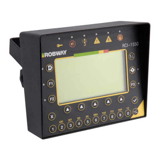
Page 14 of 72 OPERATING INSTRUCTIONS 5.1 The LCD Display Please see “RCI-1550 Operator’s Display Functions” on previous page for details and description of each function. 5.1.1 The Bar Graph This is the rectangular bar that is in the top centre of the LCD. This gives an “analogue” indication of the percentage the current load is of the Safe Working Load. -
Page 18: Angle
Page 15 of 72 5.1.4 Angle This is the current boom angle. This angle will be either the MAIN BOOM, OR the LUFFING FLY (when selected and in use) 5.1.5 Radius Shows the operating radius for the CURRENT CONFIGURATION and DUTY and WINCH selection. -
Page 19: Error Codes
Page 16 of 72 5.1.7 Error Codes Additionally, the lower area display LCD is used to display ERROR codes when any errors are detected. Should the operator press the ACK button with an error code number displayed, the text window will revert to normal until a different error condition arises, or the acknowledge timeout expires. -
Page 20: Ok (4) Key
Page 17 of 72 second time the letter will change to the second above the key and so on. If no key is pressed for approximately 1 second the character on the screen will be accepted as being correct and the display will move to the next character. -
Page 21: Led Indicators
Page 18 of 72 If after this function is initiated, the boom is raised more than 10 degrees, this function will reset to normal crane operation. This is necessary to ensure overall safe crane operation. Temporary/ATB Rigging mode, which is essentially the same as normal rigging mode with the exception that it over-rides motion cuts for only a limited period or time. -
Page 22: Audible Alarm Disabled Led
Page 19 of 72 5.3.2 Audible Alarm Disabled LED Illuminated when the in cabin alarm has been cancelled. This occurs when the operator presses the ACK soft menu button to acknowledge an error. Acknowledging an error effectively cancels the alarm for that error for a period of time. The amount of time the error will remain acknowledged is determined by the setting for this option. -
Page 23: Over-Ride Key-Switch (If Fitted)
Page 20 of 72 Over-ride Key-Switch (If fitted) Should crane overload be reached (or other limitations exceeded, such as maximum radius, minimum angle, winch line-pull etc), the system will activate the motion cut relay, if installed. This will then stop further over-loading of the crane. To bypass or temporarily override motion cut, the operator can use the over-ride key which should be held by the site-supervisor. -
Page 24: On Power Up
Page 21 of 72 As soon as power is applied to the RCI-1550, its display and other indicators should light up and the RCI-1550 should go through its self-test operation. 5.6.1 On Power Up Upon power being supplied, a test pattern is written to the LCD that completely blackens it and all LEDs will be active. -
Page 25: Function Codes
Page 22 of 72 winch), the Lift in progress screen will be displayed. This inhibits the altering of configuration once a lift has begun. If it is imperative to change the configuration even though a lift is being monitored, it is possible to change the duty and or falls in calibration mode provided you have the correct access code. -
Page 26: Data Logging And Data Down-Loading
Page 23 of 72 5.7.3.2 Display Units This option allows the operator to view information in either metric or imperial units according to personal preference. Selection of the “Change Units” item can be performed at any time (ie. even during a lift). 5.7.3.3 LCD Contrast This allows the operator to adjust the LCD for optimum contrast. -
Page 27: Installation - General
Page 24 of 72 INSTALLATION - GENERAL Setting Up the Crane Lower the crane boom to a safe and convenient position for installation of system components. High tensile booms require proper welding procedure specifications. Obtain specialist assistance in these cases. Please refer General... -
Page 28: Length Sensors
Page 25 of 72 Length Sensors 6.3.1 GENERAL Fix the recoil drum and pay-out cable to the RHS side of the main boom (LH installations require the electronic angle sensor to be re-positioned on its mount, (refer to the above BAS section) by welding the mounting bracket provided. -
Page 29: 110' Length Sensor - (Drurw33Laa)
Page 26 of 72 13m/26m/35m Recoil Drums 6.3.2 INSTALLATION- (Please read through before starting) Ensure that the face onto which the unit is to be mounted is flat, vertical and parallel to the line of cable pay-out. The mounting position should allow free uninterrupted pay-out of cable. - Page 30 Page 27 of 72 Potentiometer gear for length sensing may now be re-engaged into mesh with the driver gear. Ensure that all gear-locking screws are secure. Normally it is necessary to ensure that the boom is fully retracted or, that the machine is fully home. The pot gear should be turned by hand, in the direction driven when winding in cable, until the end stop is felt.
-
Page 31: 140' Length Sensor- (Drurw43Laa)
Page 28 of 72 13m/26m/35m Recoil Drums 6.3.3 Please read through before starting INSTALLATION- ( Ensure that the face onto which the unit is to be mounted is flat, vertical and parallel to the line of cable payout. The mounting position should allow free uninterrupted payout of the cable. -
Page 32: Pay-Out Cable
Page 29 of 72 The potentiometer gear for length sensing may now be re-engaged into mesh with the driver gear. Ensure that all gear locking screws are secure. Normally it is necessary to ensure that the boom is fully retracted or, that machine is fully home. The pot gear should be turned by hand, in the direction driven when winding in cable, until the end stop is felt. -
Page 33: Bob-Weight (Both Types Of Switches)
Page 30 of 72 6.4.4 Bob-weight (both types of switches) Hang the bob weight assembly from the switch eye after cutting the chain to length if desired to suit winch line speed. Repeat the procedure if required for rooster or fly jib. Consult installation drawings at the rear of this manual. -
Page 34: Display Unit
Page 31 of 72 Display Unit Fit the RCI-1550 Display Unit in a convenient position in the cab such that the operator can view the display and reach the push buttons comfortably Check bonding between enclosure and chassis. If a good bond cannot be ensured through the mounting bracket, then install earth strap. -
Page 35: Control Unit
Page 32 of 72 Control Unit The Control Unit (CU) contains the termination points for all modules within the RCI-1550 system. It also contains all the user interfaces, signal conditioning and processing circuitry required to satisfy the RCI/LMI functionality. The CU enclosure is a powder coated steel and carries an environmental protection rating of IP 65 which is suitable for internal or external mounting. - Page 36 Robway Safety Systems Page 33 of 72 The RS-485 signals are electrically isolated from the power and care must be take to ensure that no short circuit is introduced between them, otherwise the unit's transient protection will be compromised. Transient protection has been included on all inputs. All internal power rails are current limited and short circuit protected using re-settable fuses.
-
Page 37: Cpu Section
Page 34 of 72 6.8.2 CPU Section The processor is an 8051 derivative which contains a number of enhancements over the standard 8051, including an on-board 10 bit ADC. For most applications this degree of resolution is more than adequate. The data memory is in the form of a single package which contains the memory device with real time clock (RTC) and integral lithium battery. -
Page 38: Analog Input Section
Page 35 of 72 High Capacity Memory: up to 4MB Flash. RS-232: 9600 baud (8N1) RS-485: 19,200 baud. (8N1) On-board ADC: 10 bit PWM output: 8 bit. 6.8.3 Analog Input Section The analog section is takes advantage of the CPU’s on board 10bit ADC. This board can support up to four load cells, three angle sensors and three length sensors. -
Page 39: Digital Io Section
Page 36 of 72 Connect as per connection diagram in rear in manual. 6.8.4 Digital IO Section Refer to drawings at the rear of this manual for this item. The DIO section provides general-purpose inputs and output capable of sensing the state of 8 switch inputs and controlling 8 relay outputs. - Page 40 Page 37 of 72 6.8.4.3 Outputs All eight outputs consist of normally open voltage free contacts that close when the output is on. Each output is isolated from all others. Hence to have an output switch high one side must be tied to the supply and the other is used to drive the load.
- Page 41 Page 38 of 72 6.8.4.7 Anti-Two Block input Refer to DIO connection drawing in the rear of the manual. Provision has been made on the board for the direct activation of Output 1 via an external switch. This produces an instantaneous output signal, avoiding the possibility of delays caused by software.
-
Page 42: Upgrading To Rci-1550 From Earlier Robway Model Displays
Page 39 of 72 1. Permanent display damage may occur if incorrect motion-cut connections are made. 2. POWER MUST BE DISCONNECTED before attempting connections. 3. NEVER insert larger capacity fuses than those originally supplied. 4. Obtain specialist assistance if you are unfamiliar with crane electrics. - Page 43 Page 40 of 72 However, it is recommended that; On Tower cranes, that the integral Lightning Protector of the single sheave load-pin be disconnected and replaced by our latest stand-alone version. All earlier version systems used negatively switched motion-cut output signals. The RCI-1550 can be configured for either negative or positive type outputs.
-
Page 44: Calibration
Page 41 of 72 CALIBRATION Calibration Purpose The monitoring sensors (Load-cells, Boom angle, Boom length etc) require calibration (scaling) so that their output directly relates to the crane. 7.1.1 Entering Calibration Mode and Selecting calibration functions. Make sure that the correct duty number, winch and falls are selected before entering Calibration mode. -
Page 45: General Information Regarding Text Editing
Page 42 of 72 If view mode is requested the message “View access granted” will be displayed. If calibration mode is required the operator must enter a PIN and then press the OK button. If the PIN is correct and the controller enters calibration mode then the message “Cal access granted”... -
Page 46: View Main Load And View Aux Load Items
Page 43 of 72 7.2.2 VIEW MAIN LOAD and VIEW AUX LOAD items Displays the Main load VIEW MAIN LOAD F01: Load = 100.12 hh:mm Diagram 9: view main load 7.2.2.1 CAL MAIN LOW and CAL AUX LOW items Read and do ‘Set gain transducer 1’ and 2 followed by ‘Testing and Calibrating Transducers’... -
Page 47: View Boom Angle Item
Page 44 of 72 7.2.2.2 CAL MAIN HIGH and CAL AUX HIGH items Allows the main winch and aux winch high load to be calibrated by using the numeric buttons. The current load value is displayed and below it the edited value. Once the edit is complete pressing OK will result in the Display request the controller to do a calibration change. -
Page 48: View Jib Angle Item
Page 45 of 72 7.2.3.2 CAL HIGH BOOM ANGLE item The graphical LCD will appear similar to CAL LOW BOOM ANGLE. 7.2.4 VIEW JIB ANGLE item This function code item is only available for Luffing fly systems. The graphical LCD will appear similar to VIEW BOOM ANGLE. 7.2.4.1 CAL LOW J.ANGLE item This function code item is only available for Luffing fly systems. -
Page 49: Set Gain Trans 2 Item
Page 46 of 72 SET GAIN TRANS 1 F13: Uncal.: Gain : 2 mV/V hh:mm Diagram 15 7.2.6.1 VIEW TRANS 1item Allows viewing of the raw, calibrated, and health signal for transducer 1. The graphical LCD will appear as shown: VIEW TRANS 1 F14: Uncal. -
Page 50: No. Of Samples Item
Page 47 of 72 SET MUX. DELAY F22: Mux delay : hh:mm Diagram 17 7.2.9 NO. OF SAMPLES item This menu item is used to stabilise the display in the event that the numbers are changing erratically. The graphical LCD will show the number of samples currently being used to average the sensor inputs. -
Page 51: Set Rigging Load Threshold Item
Page 48 of 72 SET LIFT VALUE F23: 8.23 Current = 23.12 Edit = hh:mm Diagram 19 7.2.11 SET RIGGING LOAD Threshold item Rigging the crane often requires that the boom be positioned outside of the normal operating regions of the load chart. It is not generally safe practice for the crane to be placed in such positions however, at times such actions are necessary. -
Page 52: Set Rigging Length Threshold Item
Page 49 of 72 The installer must satisfy themselves that any value entered here is in accordance with the crane manufacturer or their agents. 7.2.12 SET RIGGING LENGTH Threshold item This item is, once again, used for rigging. The rigging length is the maximum length allowed during rigging operations. -
Page 53: View Directions Item
Page 50 of 72 Maximum boom deflection occurs when the boom is fully telescoped and a load, which approaches the SWL, is suspended on the hook. On duties where the winches are both assumed to be reeved over the main boom head it is necessary to calibrate only for the main winch (winch 1). -
Page 54: View Digital I/P Item
Page 51 of 72 VIEW LOADCHART F25: 3 4.43 Main SWL: 23.23 Aux SWL: 32.45 Main Rad.: 31.13 Aux Rad.: hh:mm Diagram 22 7.2.17 VIEW DIGITAL I/P item The state of the digital inputs can be viewed on the graphical LCD by using this function code. -
Page 55: Set Time Item
Page 52 of 72 7.2.19 SET TIME item When changing the time, the graphical LCD will appear as shown in the following diagram. The time displayed is in the format HH:MM:SS. An invalid time will cause an error message to appear. Note: The seconds can’t be edited and will always be “00”. - Page 56 Page 53 of 72 The Cal data item of interest needs to be selected before viewing can occur. This is achieved in a similar method to selecting main menu items ( see diagram 27 ). VIEW CAL-DATA F32: Angle Length Radius Amplifier1 Load1(up)
-
Page 57: Change Duty Item
Page 54 of 72 To edit an item, use the Up/Down buttons to move the cursor to the item you wish to edit. Then use the numeric buttons as in previous edits to enter the new values. The Ok button should be pressed to set the new values or use cancel to abort the edit. -
Page 58: Erase Cal-Table! Item
Page 55 of 72 7.2.26 ERASE CAL-TABLE! item The Display will prompt the operator to press OK if he wishes to erase the Cal Table . Pressing OK here will clean out the memory system and default back to hard coded software. Any on- site changes made will be lost. -
Page 59: Viewing Errors
Page 56 of 72 If you only want to verify the current value press the CANCEL key when finished viewing, Now you should be back at the F-xx prompt and can continue on with the next operation. Please note that the value of these variables is very important as they affect the safe operation of the RCI-1550 indicator. -
Page 60: Verifying Operation Of Sensors
Page 57 of 72 7.2.29 Verifying Operation Of Sensors Before you start calibrating the RCI-1550, make sure that the sensors are working correctly and their signals reach the RCI-1550. The RCI-1550 'sees' the crane and its surroundings through sensors. The signals from these sensors are represented as numbers inside the RCI-1550. -
Page 61: Map Of Calibration (Suggested Order)
Page 58 of 72 Map of Calibration (suggested order) Set date and Time Verify the raw counts stay within 33-999 for full working range of all sensors. Ensure all digital inputs (switched) are wired correctly, incl. ATB. Ensure all digital outputs (switched) are wired correctly. Review all geometry Function code settings for correctness Check / Set the following function codes •... -
Page 62: Calibrating Boom Angle
Page 59 of 72 CALIBRATING BOOM ANGLE 7.5.1 Calibrating a low boom angle • Safely luff the boom down to a low angle, eg. 30°, • Enter calibration mode and select the correct function code for calibrating low boom angle, •... -
Page 63: Calibrating Jib Angle (Luffing Fly Jibs Only)
Page 60 of 72 CALIBRATING JIB ANGLE (luffing fly jibs only) 7.6.1 Calibrating low Jib angle • Ensure that the angle sensor is mounted on the luffing fly and the cable is connected, • Safely luff the jib down to a low angle ( eg. 30° to the horizon ), •... -
Page 64: Calibrating Boom Length
Page 61 of 72 CALIBRATING BOOM LENGTH • Fully retract the boom, • Enter calibration mode and select the correct function code for calibrating SHORT (LO) boom length, • Use the UP/DOWN keys to ramp the display to the required value then press ENTER to accept this value. -
Page 65: Calibrating Tensiometer Based Systems
Page 62 of 72 CALIBRATING TENSIOMETER BASED SYSTEMS 7.8.1 Calibrate the Main Winch with light load. (Ensure the correct winch and falls are selected) Note: This procedure assumes that the following has already been done, if not then load calibration will be incorrect. - Boom angle and length has been calibrated and verified. -
Page 66: Calibrate The Aux Winch With Light Load
Page 63 of 72 Select the correct Function code number from the Function code list at the rear of this manual. Use the up/down arrows to enter the correct numerical data. Enter data to represent the lifted weight for MAIN ROPE HEAVY LOAD. If the crane has an Aux. -
Page 67: Maintenance
Page 64 of 72 MAINTENANCE When maintenance is to be performed on the RCI-1550 system, care must be taken to ensure that the level of safety is not reduced. Such a reduction in the level of safety can easily be done by the careless use of tools or test equipment, either directly or by damage to safety components, wiring or clearances. -
Page 68: In-Cabin Items
Page 65 of 72 In-cabin items Ensure the display unit mounting is solid and vibration free and that the display cable connection is firmly connected. Ensure the display cable is not pinched or caught or may become suspect to damage on route from the Display Unit to the Controller Unit outside the cabin. -
Page 69: Recoil Drum
Page 66 of 72 RECOIL DRUM GENERAL In normal use little attention to maintenance is required. DRUKO413/25/35 8.4.1 Periodically, simply observe that reel behaves correctly when extending and, retracting cable without hesitation. Check wound cable for damage at anchor pulley and generally. At major machine service intervals, remove reel cover and check that interior is clean and dry. -
Page 70: 140' Recoil Drum - (Drurw43Laax)
Page 67 of 72 Re-assemble reel in reverse order, paying particular attention to correctly locating cable compartment boss onto shaft and that socket screws are correctly located in shaft dimples. Use Loctite “Screwlock.” Unit may now be fully re-assembled and full setting up procedure, (installation may be completed. - Page 71 Page 68 of 72 Turn unit over to stand on its 4 cover studs and withdraw cable from shaft. Release socket screws, 2 at 90°, holding cable compartment onto shaft and withdraw compartment, complete with cable. The spring compartment is now exposed and, the 4 nyloc nuts and the cover may be removed. The rewind spring will now be visible and seen to be held in a captive band.
-
Page 72: Inspection After Maintenance
Page 69 of 72 INSPECTION AFTER MAINTENANCE Robway consider it essential by that a detailed Inspection is performed following any maintenance to ensure that the equipment and installation continue to comply with the documentation. Any deviations to supplied documentation should be updated to inform any future service attendance. -
Page 73: Electrical Specifications
Page 70 of 72 ELECTRICAL SPECIFICATIONS Controller Automotive alternator DC supply, nominally 12V or 24V DC. Approximately 20VA (Watts). Power Consumption Operating -20°C to +60°C Temperature Range tested to (-30°C to + 70°C) Expected Resistance Values Load Cells Should have the following nominal resistance values, for a standard 350 ohm cell (note that these values may vary slightly from cell to cell). - Page 74 Page 71 of 72 Between the signal and each of the excitation wires varying between 0 and 500 ohms Between any of the wires and chassis or shield high ohms, or open circuit Voltage Levels Load cell excitation 4.0V Angle excitation 4.0V Length excitation 4.0V...
-
Page 75: 10 Appendices
Page 72 of 72 10 APPENDICES 10.1 General Arrangement Drawings Where required (e.g. Special Systems), a set of General Arrangement drawings and specific wiring details are supplied on separate sheets, in addition to the standard drawings contained in this manual. These extra drawings are not supplied on standard systems. File : 1550-Telescopic-HRT.DOC Issue Date: - 01/08/05... - Page 77 INSTALLATION & HARDWARE DIMENSIONAL DRAWINGS The following are the General Arrangement and basic dimensional drawings of the System. Please note that these are basic System parts, some parts shown may not have been ordered and supplied...
- Page 117 SERVICE DRAWINGS The following drawings are mainly electrical connection diagrams inside the RCI-1550 Control Unit for service reference only.
Need help?
Do you have a question about the RCI-1550 HRT and is the answer not in the manual?
Questions and answers