Sign In
Upload
Manuals
Brands
LSI-Robway Manuals
Lifting Systems
RCI-1550 HRT
LSI-Robway RCI-1550 HRT Boom System Manuals
Manuals and User Guides for LSI-Robway RCI-1550 HRT Boom System. We have
2
LSI-Robway RCI-1550 HRT Boom System manuals available for free PDF download: Instruction Manual
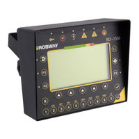
LSI-Robway RCI-1550 HRT Instruction Manual (126 pages)
Telescopic Boom System
Brand:
LSI-Robway
| Category:
Lifting Systems
| Size: 6 MB
Table of Contents
Table of Contents
3
1 Welcome to Robway Products
7
2 Special Notes
10
Brandnames, Tradenames and Trade Marks
10
Important Safety Notice
10
Limited Product Warranty
11
Glossary of some Used Terms
11
3 Introduction
12
Manual Contents
12
Scope of Manual
12
Intended Audience
12
Personnel Qualifications
12
4 System Description
13
Application
13
Purpose
14
Capabilities
14
Available Options
15
5 Operating Instructions
17
5.1 the LCD Display
17
The Bar Graph
17
Swl
17
Length
17
Angle
18
Radius
18
Load
18
Error Codes
19
The Display Keypad
19
Function Key (F1, F2, F3)
19
Soft Menu Keys
19
Alpha-Numerical Keys
19
Ok (4) Key
20
Cancel (5) Key
20
Tare Key
20
Rigging Key
20
Led Indicators
21
Override LED
21
Audible Alarm Disabled LED
22
Indicator (Anti-Two-Block or Over-Hoist)
22
Approach to Rated Capacity LED
22
100% Capacity Exceeded LED
22
Motion Cut LED
22
Over-Ride Key-Switch (if Fitted)
23
Disable Key Switch (if Fitted)
23
Turning on the Rci-1550
23
On Power up
24
Menu Navigation
24
Config Change Menu
24
Function Codes
25
Display Options Menu
25
Data Logging and Data Down-Loading
26
6 Installation - General
27
Setting up the Crane
27
Angle Sensor ( Telescopic Boom Cranes )
27
Changing from RHS to LHS Mounting
27
Length Sensors
28
General
28
110' Length Sensor - (DRURW33LAA)
29
140' Length Sensor- (DRURW43LAA)
31
Pay-Out Cable
32
Anti-Two-Block ( if Installed )
32
Rectangular Type Anti-Two Block Switches
32
Tubular Type Anti-Two Block Switches
32
Multiple Anti-Two Block Switches
32
Bob-Weight (both Types of Switches)
33
Load-Line (Line-Pull) Based Systems
33
Overview
33
Cabling and Glands
33
Display Unit
34
Control Unit
35
Power Supply (PS)
35
CPU Section
37
Analog Input Section
38
Digital IO Section
39
Upgrading to Rci-1550 from Earlier Robway Model Displays
42
7 Calibration
44
Calibration Purpose
44
Entering Calibration Mode and Selecting Calibration Functions
44
Function Codes Menu Item
44
General Information Regarding Text Editing
45
Calibration Functions Breakdown
45
EXIT CALIBRATION Item
45
VIEW MAIN LOAD and VIEW AUX LOAD Items
46
VIEW BOOM ANGLE Item
47
VIEW JIB ANGLE Item
48
VIEW LENGTH Item
48
SET GAIN TRANS 1 Item
48
SET GAIN TRANS 2 Item
49
SET MUX. DELAY Item
49
NO. of SAMPLES Item
50
SET LIFT VALUE (Threshold) Item
50
SET RIGGING LOAD Threshold Item
51
SET RIGGING LENGTH Threshold Item
52
CORRECT RADIUS (Unladen Boom) Item
52
CORRECT RADIUS (Laden Boom) Item
52
VIEW DIRECTIONS Item
53
VIEW LOAD-CHART Item
53
VIEW DIGITAL I/P Item
54
SET DATE Item
54
SET TIME Item
55
DOWNLOAD LOGGER Item
55
VIEW CAL-DATA Item
55
CHANGE DUTY Item
57
CHANGE FALLS Item
57
BACK up CAL-TABLE Item
57
RESTORE CAL-TABLE Item
57
ERASE CAL-TABLE! Item
58
User Variables
58
Viewing Errors
59
Verifying Operation of Sensors
60
Tools Required for Calibration
60
Map of Calibration (Suggested Order)
61
Calibrating Boom Angle
62
Calibrating a Low Boom Angle
62
Calibrating a High Boom Angle
62
CALIBRATING JIB ANGLE (Luffing Fly Jibs Only)
63
Calibrating Low Jib Angle
63
Calibrating High Jib Angle
63
Calibrating Boom Length
64
Calibrating Tensiometer Based Systems
65
Calibrate the Main Winch with Light Load
65
Calibrate the Main Winch with Heavy Load
65
Calibrate the Aux Winch with Light Load
66
Calibrate the Aux Winch with Heavy Load
66
8 Maintenance
67
Check List
67
In-Cabin Items
68
Electrical Equipment
68
Recoil Drum
69
110' Recoil Drum - (DRURW33LAAX)
69
140' Recoil Drum - (DRURW43LAAX)
70
Inspection after Maintenance
72
Records
72
9 Electrical Specifications
73
10 Appendices
75
Advertisement
LSI-Robway RCI-1550 HRT Instruction Manual (85 pages)
Lattice Boom System
Brand:
LSI-Robway
| Category:
Lifting Systems
| Size: 2 MB
Table of Contents
Table of Contents
3
1 Important Safety Notice
7
2 Special Notes
7
Brandnames, Tradenames and Trade Marks
7
Notice
7
Limited Product Warranty
8
Glossary of some Used Terms
8
3 Introduction
8
Manual Contents
8
Scope of Manual
8
Intended Audience
8
Personnel Qualifications
8
4 System Description
9
Application
9
Purpose
9
Capabilities
9
Available Options
10
5 Installation - General
11
Setting up the Crane
11
Angle Sensors
11
Anti-Two-Block (if Installed)
11
Rectangular Type Anti-Two Block Switches
11
Tubular Type Anti-Two Block Switches
11
Multiple Anti-Two Block Switches
11
Bob-Weight (both Types of Switches)
12
Load-Line (Line-Pull) Based Systems
12
Overview
12
Tensiometers (Line-Riders)
12
Tension Load-Line Plate Type Load-Cell
13
Cabling and Glands
13
Display Unit
14
Control Unit
15
Power Supply (PS)
15
CPU Section
17
Analog Input Section
17
Digital IO Section
18
Upgrading to Rci-1550 from Earlier Robway Model Displays
20
6 Operating Instructions
21
The Lcd Display
21
The Bar Graph
22
Swl
22
Length
22
Angle
22
Radius
22
Load
22
Error Codes
23
The Display Keypad
23
Function Key (F1, F2, F3)
23
Soft Menu Keys
23
Alpha-Numerical Keys
23
Ok () Key
23
Cancel (X) Key
23
Tare Key
24
Rigging Key
24
Led Indicators
25
Override LED
25
Audible Alarm Disabled LED
25
Indicator (Anti-Two-Block or Over-Hoist)
25
Approach to Rated Capacity LED
25
100% Capacity Exceeded LED
25
Motion Cut LED
25
Over-Ride Key-Switch (if Fitted)
25
Disable Key Switch (if Fitted)
26
Turning on the Rci-1550
26
On Power up
26
Menu Navigation
26
Config Change Menu
27
Function Codes
27
Display Options Menu
28
Data Logging and Data Down-Loading
28
7 Calibration
29
Calibration Purpose
29
Entering Calibration Mode and Selecting Calibration Functions
29
Function Codes Menu Item
29
General Information Regarding Text Editing
30
Calibration Functions Breakdown
30
Exit Calibration Item
30
View Main Load and View Aux Load Items
30
View Boom Angle Item
31
View Jib Angle Item
32
Set Gain Trans 1 Item
32
Set Gain Trans 2 Item
32
Set MUX. Delay Item
33
No. of Samples Item
33
Set Lift Value (Threshold) Item
33
Set Rigging Load Threshold Item
34
Set Rigging Length Threshold Item
34
View Directions Item
34
View Load-Chart Item
35
View Digital I/P Item
35
Set Date Item
35
Set Time Item
36
Download Logger Item
36
View Cal-Data Item
36
Change Duty Item
37
Change Falls Item
37
Back up Cal-Table Item
37
Restore Cal-Table Item
38
Erase Cal-Table! Item
38
User Variables
38
Viewing Errors
39
Verifying Operation of Sensors
39
Tools Required for Calibration
40
Map of Calibration (Suggested Order)
41
Calibrating Boom Angle
41
Calibrating a Low Boom Angle
41
Calibrating a High Boom Angle
41
CALIBRATING JIB ANGLE (Luffing Fly Jibs Only)
42
Calibrating Low Jib Angle
42
Calibrating High Jib Angle
42
Calibrating Tensiometer Based Systems
42
Calibrate the Main Winch with Light Load
42
Calibrate the Main Winch with Heavy Load
42
Calibrate the Aux Winch with Light Load
43
Calibrate the Aux Winch with Heavy Load
43
Load / Angle Correction Software
43
What Is Load Angle Correction Software
43
How to Calculate the Load / Angle Correction Factor
44
8 Maintenance
45
Check List
45
In-Cabin Items
45
Additional Detail
45
Electrical Equipment
46
Inspection after Maintenance
46
Records
46
9 Troulbelshooting
47
Error Code List
48
Example Errors & Possible Causes
48
Problems that Do Not Produce Error Codes
49
10 Electrical Specifications
51
11 Electronic Angle Sensor Specifications
51
12 Appendices
51
Drawings Parta - System Components
53
D P a
53
Advertisement
Related Products
LSI-Robway RCI-1502 LM
LSI-Robway RCI-1502 HRT
LSI-Robway RCI-1550 LM
LSI-Robway Categories
Lifting Systems
More LSI-Robway Manuals
Login
Sign In
OR
Sign in with Facebook
Sign in with Google
Upload manual
Upload from disk
Upload from URL