Sony NW-A605 Service Manual
Digital music player
Hide thumbs
Also See for NW-A605:
- Quick start manual (12 pages) ,
- Operation manual (92 pages) ,
- Quick start manual (12 pages)
Table of Contents
Advertisement
Quick Links
NW-A605/A607/A608
SERVICE MANUAL
Ver. 1.3 2006.07
US and foreign patents licensed from
Dolby Laboratories.
Supported bit rates
MP3: 32 to 320 kbps variable bit rate-compliant
ATRAC: 48 / 64 / 66 (ATRAC3)* / 96 / 105 (ATRAC3)* /
128 / 132 (ATRAC3) / 160 / 192 / 256 / 320 kbps
* CD recording cannot be done using CONNECT Player software in
ATRAC3 at 66/105 kbps.
Sampling frequency
ATRAC, MP3: 44.1 kHz
Frequency response
20 to 20,000 Hz (single signal measurement)
FM Frequency range
87.5 to 108.0 MHz
IF (FM)
225 kHz
Antenna
Headphone cord antenna
Interface
Headphone: Stereo mini
Hi-speed USB (USB 2.0 compliant)
Signal-to-noise ratio (S/N)
80 dB or more
Operating temperature
5°C to 35°C (67°F to 95°F)
Power source
• Built-in rechargeable lithium-ion battery
• USB power (from a computer through supplied USB cable)
Battery life (continuous playback) *
ATRAC format: Approximately 45 hours (Playback at 48 kbps)
ATRAC format: Approximately 40 hours (Playback at 128 kbps)
ATRAC format: Approximately 50 hours (Playback at 132 kbps)
MP3 format: Approximately 40 hours (Playback at 128 kbps)
FM radio reception: Approximately 22 hours
* This is when the power save setting is "Save ON Normal". The battery
duration will vary depending on temperature and usage.
Sony Corporation
9-879-946-04
Connect Business Division
2006G16-1
Published by Sony Techno Create
© 2006.07
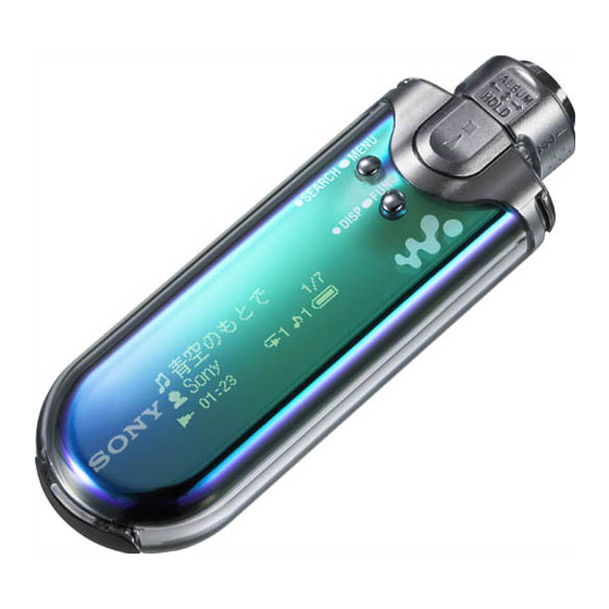
Photo : NW-A605
SPECIFICATIONS
Dimension
84.9 × 28.8 × 13.9 mm (3 3/8 × 1 3/16 × 9/16 inches)
(w/h/d, projecting parts not included)
Mass
Approx. 48 g (1.7 oz)
Supplied Accessories
Headphones (1)
USB cable (1)
Headphone extension cord (1)
Neck strap (China model only) (1)
Carrying pouch (1)
Clip (1)
This is used to clip onto your cloths
when carrying the player .
CD-ROM* (1)
- CONNECT Player software
- Operation Guide (PDF file)
* Do not attempt to play this CD-
ROM in an audio CD player.
Quick Start Guide (1)
Maximum recordable number of track (Approx.)*
Bit rate
NW-A605
NW-A607
48 kbps
345
695
64 kbps
255
520
96 kbps
170
345
128 kbps
130
260
132 kbps
125
250
160 kbps
100
205
192 kbps
85
170
256 kbps
65
130
320 kbps
50
105
Canadian Model
Chinese Model
Maximum recording time (Approx.)
Bit rate
NW-A605
48 kbps
23 hr. 00 min.
64 kbps
17 hr. 00 min.
96 kbps
11 hr. 20 min.
128 kbps
8 hr. 40 min.
132 kbps
8 hr. 20 min.
160 kbps
6 hr. 40 min.
192 kbps
5 hr. 40 min.
256 kbps
4 hr. 20 min.
320 kbps
3 hr. 20 min.
* When transferring four-minute tracks.
Design and specifications are subject to change without
notice.
NW-A608
1,350
1,000
700
525
510
420
350
260
210
DIGITAL MUSIC PLAYER
US Model
NW-A605/A607/A608
AEP Model
NW-A608
E Model
NW-A605/A607/A608
NW-A607
NW-A608
46 hr. 20 min.
90 hr. 00 min.
34 hr. 20 min.
66 hr. 40 min.
23 hr. 00 min.
46 hr. 40 min.
35 hr. 00 min.
17 hr. 20 min.
16 hr. 40 min.
34 hr. 00 min.
13 hr. 40 min.
28 hr. 00 min.
11 hr. 20 min.
23 hr. 20 min.
8 hr. 40 min.
17 hr. 20 min.
7 hr. 00 min.
14 hr. 00 min.
Advertisement
Table of Contents

Related Manuals for Sony NW-A605


Summary of Contents for Sony NW-A605
-
Page 1: Specifications
* This is when the power save setting is “Save ON Normal”. The battery 320 kbps duration will vary depending on temperature and usage. DIGITAL MUSIC PLAYER Sony Corporation 9-879-946-04 Connect Business Division 2006G16-1 Published by Sony Techno Create © 2006.07... -
Page 2: Table Of Contents
NW-A605/A607/A608 TABLE OF CONTENTS Flexible Circuit Board Repairing • Keep the temperature of the soldering iron around 270 °C during repairing. GENERAL ..............3 • Do not touch the soldering iron on the same conductor of the circuit board (within 3 times). -
Page 3: General
NW-A605/A607/A608 SECTION 1 GENERAL This section is extracted from instruction manual. - Page 4 NW-A605/A607/A608 To remove the Lithium-Ion battery Remove the board. Remove the screws using a Remove the cover B. Phillips screwdriver. Remove the cover A. Remove the battery. Remove the connector.
-
Page 5: Disassembly
NW-A605/A607/A608 SECTION 2 DISASSEMBLY Note: This set can be disassembled in the order shown below. 2-1. DISASSEMBLY FLOW 2-2. LID (CONNECTOR) (Page 6) 2-3. CABINET (TOP), CABINET (INNER) (Page 6) 2-4. MAIN SECTION (Page 7) 2-5. MAIN BOARD 2-7. LITHIUM (ION) STORAGE BATTERY... -
Page 6: Lid (Connector)
NW-A605/A607/A608 Note: Follow the disassembly procedure in the numerical order given. 2-2. LID (CONNECTOR) 1 two claws 3 two tapping screws 1.4 2 Open the lid (connector) in the direction of the arrow. 4 lid (connector) 2-3. CABINET (TOP), CABINET (INNER) -
Page 7: Main Section
NW-A605/A607/A608 2-4. MAIN SECTION 5 main section 1 sheet (connector) 2 stopper cushion 4 Remove the soldering. 3 connector (CN501) 2-5. MAIN BOARD 1 two sheets (flexible) 2 five claws 6 spacer (shield plate w) 7 two sheets (sheet, insulating) -
Page 8: Organic El Indicator Module
NW-A605/A607/A608 2-6. ORGANIC EL INDICATOR MODULE 1 Remove the SW board in the direction of the arrow. 5 organic EL indicator module 3 adhesive sheet (panel) 2 SW board 4 chassis 2-7. LITHIUM (ION) STORAGE BATTERY 1 lithium (ion) storage battery... -
Page 9: Cover (Jack), Arm (Shuttle)
NW-A605/A607/A608 2-8. COVER (JACK), ARM (SHUTTLE) 1 two claws 2 cover (jack) two springs (slide) 3 two springs (slide) 4 knob (shuttle), arm (shuttle), spring (shuttle) 7 arm (shuttle) printed side 5 two claws 6 knob (shuttle), spring (shuttle) -
Page 10: Spring (Shuttle), Knob (Shuttle)
NW-A605/A607/A608 2-9. SPRING (SHUTTLE), KNOB (SHUTTLE) How to install the spring (shuttle) p rinted side 1 Tentatively install the spring (shuttle), and move in the direction of the arrow. printed side 2 spring (shuttle) 1 spring (shuttle) printed side knob (shuttle) -
Page 11: Test Mode
NW-A605/A607/A608 SECTION 3 TEST MODE 1. How to Enter the Test Mode 3. Display Check Mode 1. Set the SHUTTLE switch in the HOLD position. 1. While the machine is in the TEST mode, set the SHUTTLE 2. While keeping pressing the Nx button in the HOLD switch to the ALBUM position. -
Page 12: Diagrams
NW-A605/A607/A608 SECTION 4 DIAGRAMS Note on Schematic Diagram: Note on Printed Wiring Board • All capacitors are in µF unless otherwise noted. (p: pF) 50 WV • X : parts extracted from the component side. • Y : parts extracted from the conductor side. -
Page 13: Block Diagram
NW-A605/A607/A608 4-1. BLOCK DIAGRAM IC508 RESET VOUT VDD 4 S710 IC450 IC1461 RESET NOR FLASH/SRAM NAND FLASH RAM Q506 Q507 RESET DQ0-DQ15 A0-A19 A0-A5 I/O1 - I/O8 29,31,33,35,38 25-18,8-1 25-20 40,42,44,30,32,34 29 - 32, 41 - 44 16 17 18 19 8 9... -
Page 14: Printed Wiring Board - Main Board (Side A)
NW-A605/A607/A608 4-2. PRINTED WIRING BOARD – MAIN BOARD (SIDE A) – :Uses unleaded solder. MAIN BOARD (SIDE A) SW BOARD CN702 (Page 22) IC504 IC601 IC502 IC507 BT901 RECHARGEABLE BATTERY Li-ion Mn 1PC, 4.0V IC2001 1-868-944- (11) LCD901 ORGANIC EL INDICATOR MODULE •... -
Page 15: Printed Wiring Board - Main Board (Side B)
NW-A605/A607/A608 4-3. PRINTED WIRING BOARD – MAIN BOARD (SIDE B) – :Uses unleaded solder. ✩ IC450 on MAIN board cannot be replaced individually. Replacement of IC400, IC450, IC901 on MAIN board Replace it with “MAIN BOARD, COMPLETE” for service. requires a special tool. -
Page 16: Schematic Diagram - Main Board (1/6)
NW-A605/A607/A608 4-4. SCHEMATIC DIAGRAM – MAIN BOARD (1/6) – • See page 12 for Waveforms. CN901 C620 L601 C622 C624 C621 L602 0.47 0.47 X601 C607 16.934MHz R915 R603 R601 R905 R630 C901 C902 L901 R913 R602 R605 C614 C608... -
Page 17: Schematic Diagram - Main Board (2/6), Sw Board
NW-A605/A607/A608 4-5. SCHEMATIC DIAGRAM – MAIN BOARD (2/6), SW BOARD – • See page 12 for Waveform. • See page 23 for IC Block Diagram. IC1461 R1466 R1464 IC401 C462 RV5C348A-E2 X402 32.768kHz TP407 TP402 TXD0 TP403 RXD0 TP401 DGND... -
Page 18: Schematic Diagram - Main Board (3/6)
NW-A605/A607/A608 4-6. SCHEMATIC DIAGRAM – MAIN BOARD (3/6) – • See page 12 for Waveform. • See page 26 for IC Pin Function Description. VDR405 R423 470k R453 470k R432 R433 C406 TP404 TXD1 VDR402 TP405 RXD1 TP418 R430 TP409... -
Page 19: Schematic Diagram - Main Board (4/6)
NW-A605/A607/A608 4-7. SCHEMATIC DIAGRAM – MAIN BOARD (4/6) – ✩ IC450 on MAIN board cannot be replaced individually. Replace it with “MAIN BOARD, COMPLETE” for service. R450 R454 C450 CN801 R811 D801 R806 L801 RSX101M-30TR ✩ R812 R803 C811 C801... -
Page 20: Schematic Diagram - Main Board (5/6)
NW-A605/A607/A608 4-8. SCHEMATIC DIAGRAM – MAIN BOARD (5/6) – • See page 23, 24 for IC Block Diagrams. • See page 25 for IC Pin Function Description. IC302 MAX4764ETB-T R307 R207 R303 R107 R305 R304 100k R306 100k R302 470k... -
Page 21: Schematic Diagram - Main Board (5/6)
NW-A605/A607/A608 4-9. SCHEMATIC DIAGRAM – MAIN BOARD (6/6) – • See page 24 for IC Block Diagrams. TP503 VDD_USB3.3 TP505 VDD_CORE1.25 IC505 R537 TPS62200DBVR L501 C510 R538 TP506 VDD_IO2.8 Q502 IC501 R523 NTHS2101PT1G SN412005RHLR 470k TP507 VDD_NAND2.8 R508 C505 C503... -
Page 22: Printed Wiring Board - Sw Board
NW-A605/A607/A608 4-10. PRINTED WIRING BOARD – SW BOARD – :Uses unleaded solder. SW BOARD (SIDE A) SW BOARD (SIDE B) S708 > S709 SEARCH/MENU S707 S704 S706 ALBUM DISP/FUNC HOLD VDR701 MAIN BOARD VDR704 CN701 (Page 14) S701 VDR705 VDR703... - Page 23 NW-A605/A607/A608 • IC Block Diagrams – MAIN Board – IC301 TB2173FTG VOLUME/SWITCH MODE PORT C-SW /PORT CONTORL SWITCH BEEP OUTA 1 OUTA – OUTC 3 VOLUME IN2A PW GND 4 VOL OUTA – OUTB 5 – PRE INA BEEP OUTB 6...
- Page 24 NW-A605/A607/A608 IC505, IC506 TPS62200DBVR Driver Shoot-Through Logic – – – Control Logic – VREF=0.5V Conpensation 1MHz – Soft Start Oscillator Comparator V(Comp) Sawtooth Generator Undervoltage Lockout Blas Supply IC2001 TEA5767HN IGAIN POWER GAIN SUPPLY STABILIZATION AGND DEMODULATOR VCCA SOFT RESONANCE...
- Page 25 NW-A605/A607/A608 • IC Pin Function Description MAIN BOARD IC2001 TEA5767HN (RECEIVER) Pin No. Pin Name Description — Not used CPOUT Charge pump output of the synthesiser PLL VCOTANK1 VCO tuned circuit output 1 VCATANTK2 VCO tuned circuit output 2 VCC (VCO) —...
- Page 26 NW-A605/A607/A608 MAIN BOARD IC400 CXR704060-202GA (SYSTEM CONTROLLER, SERIAL INTERFACE, D/A CONVERTOR) Pin No. Pin Name Description VDIO0 — I/O interface positive power supply terminal PM4/A12 Address signal PM5/A13 Address signal PM6/A14 Address signal PM7/A15 Address signal PN0/A16 Address signal PN1/A17...
- Page 27 NW-A605/A607/A608 Pin No. Pin Name Description PB3/D11 Data signal PB4/D12 Data signal PB5/D13 Data signal PB6/D14 Data signal PB7/D15 Data signal PA0/PWM General purpose port A PA1/SDA General purpose port A (Open-drain) PA2/SCL General purpose port A (Open-drain) PC0/SCK0 ch0 clock input/output...
- Page 28 NW-A605/A607/A608 Pin No. Pin Name Description ADC analog input ADC analog input ADC analog input ADC analog input ADC analog input ADC analog input AN6/INT8 External interrupt request AN7/INT9 External interrupt request System reset terminal RAMBK RAM backup control signal input terminal VDBK —...
- Page 29 NW-A605/A607/A608 Pin No. Pin Name Description PQ1/PGMTR1 General purpose port Q PQ2/PGMTR2 General purpose port Q PQ3/PGMTR3 General purpose port Q General purpose port Q General purpose port Q General purpose port Q General purpose port Q DVSS8 — GND terminal VDIO7 —...
- Page 30 NW-A605/A607/A608 Pin No. Pin Name Description PL0/A0 Address signal PL1/A1 Address signal PL2/A2 Address signal PL3/A3 Address signal PL4/A4 Address signal PL5/A5 Address signal PL6/A6 Address signal PL7/A7 Address signal PM0/A8 Address signal PM1/A9 Address signal PM2/A10 Address signal PM3/A11...
-
Page 31: Exploded Views
NW-A605/A607/A608 Ver. 1.3 SECTION 5 EXPLODED VIEWS NOTE: • -XX and -X mean standardized parts, so they • The mechanical parts with no reference • Abbreviation may have some difference from the original number in the exploded views are not supplied. -
Page 32: Overall-2
NW-A605/A607/A608 Ver. 1.3 5-2. OVERALL-2 LCD901 supplied J301 BT901 Ref. No. Part No. Description Remark Ref. No. Part No. Description Remark - Continued from page 31 - 2-595-369-02 BUTTON (BOTTOM) 2-595-362-02 CABINET (BOTTOM) 2-595-363-01 SHEET (BATTERY), ADHESIVE 3-239-122-01 CUSHION (SP) -
Page 33: Electrical Parts List
NW-A605/A607/A608 Ver. 1.3 SECTION 6 MAIN ELECTRICAL PARTS LIST NOTE: • Due to standardization, replacements in the • Items marked “*” are not stocked since they When indicating parts by reference number, parts list may be different from the parts are seldom required for routine service. - Page 34 6-707-478-01 IC M66592WG C2006 1-100-506-91 CERAMIC CHIP 6.3V IC1461 6-707-829-01 IC K04SONY99 (NW-A607) C2011 1-164-943-81 CERAMIC CHIP 0.01uF IC1461 6-707-830-01 IC K04SONY95 (NW-A605) IC1461 6-708-972-01 IC K05SONYMEW (NW-A608) C2012 1-107-819-11 CERAMIC CHIP 0.022uF C2013 1-107-819-11 CERAMIC CHIP 0.022uF IC2001 6-706-069-01 IC TEA5767HN...
- Page 35 NW-A605/A607/A608 MAIN Ref. No. Part No. Description Remark Ref. No. Part No. Description Remark Q502 6-550-861-01 TRANSISTOR NTHS2101PT1G R429 1-218-973-11 RES-CHIP 1/16W Q503 6-551-346-01 TRANSISTOR 2SK3541T2L Q504 6-550-747-01 TRANSISTOR 3LP01S-K-TL-E R430 1-218-945-11 RES-CHIP 1/16W Q505 6-551-346-01 TRANSISTOR 2SK3541T2L R431 1-218-945-11 RES-CHIP...
- Page 36 NW-A605/A607/A608 MAIN Ref. No. Part No. Description Remark Ref. No. Part No. Description Remark R625 1-218-953-11 RES-CHIP 1/16W R2001 1-218-977-11 RES-CHIP 100K 1/16W R626 1-218-953-11 RES-CHIP 1/16W R627 1-218-941-81 RES-CHIP 1/16W R2002 1-218-965-11 RES-CHIP 1/16W R630 1-218-989-11 RES-CHIP 1/16W R2003...
- Page 37 NW-A605/A607/A608 Ver. 1.3 Ref. No. Ref. No. Part No. Part No. Description Description Remark Remark < SWITCH > S701 1-786-862-21 SWITCH, PUSH (1 KEY) (.–) S704 1-771-851-41 SWITCH, TACTILE (SMD) (DISP/FUNC) S706 1-771-851-41 SWITCH, TACTILE (SMD) (Nx) S707 1-786-863-21 SWITCH, PUSH (1 KEY)
-
Page 38: Revision History
Also, clicking the version at the upper right on the revised page allows you to jump to the next revised page. Ver. Date Description of Revision 2005.11 2005.12 Addition of parts number of MAIN board (ECN-ECB40256) 2006.01 Addition of US model for NW-A605/A607/A608 Addition of SILVER model for NW-A607 Korean model (SPM-05209) 2006.07 Addition of Chinese model for NW-A605/A607/A608...
Need help?
Do you have a question about the NW-A605 and is the answer not in the manual?
Questions and answers