Table of Contents
Advertisement
512C Series
Product Manual
HA389196 Issue 7
! Copyright Eurotherm Drives Limited 2001
All rights strictly reserved. No part of this document may be stored in a retrieval system, or transmitted in any form or
by any means to persons not employed by a Eurotherm group company without written permission from Eurotherm
Drives Ltd.
Although every effort has been taken to ensure the accuracy of this document it may be necessary, without notice, to
make amendments or correct omissions. Eurotherm Drives cannot accept responsibility for damage, injury, or expenses
resulting therefrom.
E U R O T H E R M
D R I V E S
Advertisement
Table of Contents

Related Manuals for Eurotherm 512C/04


Summary of Contents for Eurotherm 512C/04
- Page 1 All rights strictly reserved. No part of this document may be stored in a retrieval system, or transmitted in any form or by any means to persons not employed by a Eurotherm group company without written permission from Eurotherm Drives Ltd.
- Page 2 The specifications, processes and circuitry described herein are for guidance only and may need to be adapted to the user’s specific application. Eurotherm Drives does not guarantee the suitability of the equipment described in this Manual for individual applications. Risk Assessment Under fault conditions, power loss or other operating conditions not intended, the equipment may not operate as specified.
-
Page 3: Table Of Contents
Contents Contents Page Chapter 1 E T T ING T A R T E D Introduction....................1-1 Optional Equipment ....................1-1 Equipment Inspection..................1-1 About this Manual..................1-2 Initial Steps ....................... 1-2 How the Manual is Organised ................... 1-2 Chapter 2 VE R VIE W O F T HE O NVE R T E R Component Identification................2-1 Understanding the Product Code..............2-2... - Page 4 A I N T E N A N C E A N D E P A IR Routine Maintenance ..................8-1 Repair......................8-1 Returning the Unit to Eurotherm Drives............... 8-1 Disposal ........................8-1 Chapter 9 512C E P L A C E M E NT O F W IT H 512C/512 Terminal Differences ..............9-1...
-
Page 5: Getting Started Introduction
See page 12.3 for more information. LA389745U032 EMC Installation Guidelines for Modules and Systems HA388879 A Eurotherm Drives application manual detailing EMC requirements External AC Supply (RFI) Filter Refer to Chapter 3 For 512C units without internal filters, on cable runs in excess of 25... -
Page 6: About This Manual
Enter the “Model No” from the rating label into the table at the front of this manual. It is important that you pass this manual on to any new user of this unit. This manual is for the following models from the 512C Converter Series: 512C/04 4A DC Full Load Current 512C/08... -
Page 7: An Overview Of The Converter
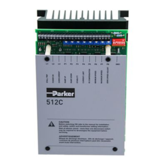
An Overview of the Converter VERVIEW OF THE ONVERTER Component Identification CONTROL TERMINAL BLOCK CONTROL HEALTH LEDS POTENTIOMETERS SWITCHES LED1 - STALL TRIP P1 - RAMP UP P2 - RAMP DOWN LED2 - POWER ON LED3 - OVERCURRENT TRIP P3 - SPEED STABILITY P4 - CURRENT LIMIT P5 - IR COMPENSATION 512C... - Page 8 An Overview of the Converter Control Features Speed Speed Control Action Closed Loop with Proportional Integral Control Speed Speed Control Control and Adjustable Stability Control Control Speed Feedback Armature Voltage Tachogenerator 100% Load Regulation 2 % Typical 0.1 % Typical Maximum Torque/Speed 20:1 100:1...
-
Page 9: Understanding The Product Code
Two numbers specifying mechanical package including livery and mechanical package style, and any option installed over and above the standard features of the product: Two numbers Livery Standard Eurotherm Drives livery 01-99 Defined customer liveries Two numbers specifying the cover: IP00 Open Frame... -
Page 10: Installing The Converter
ONVERTER IMPORTANT: Read Chapter 12: "Certification for the Converter" before installing this unit. Mechanical Installation 512C EUROTHERM DRIVES PRODUCT OVERALL FIXING SIZE SLOT DETAIL DIMENSIONS CENTRES 512C/04 240mm 160mm 90mm 210mm 148mm 15mm 512C/08 240mm 160mm 90mm 210mm 148mm 15mm... -
Page 11: Mounting The Converter
M5 Ring Lugs LOAD Green Black /Yellow Product Filter Watt Overall Dimensions Fixing Product Terminal Loss Centres Fixing 512C/04 CO389113 4mm 2 512C/08 CO389113 4mm 2 512C/16 CO389113 4mm 2 512C/32 CO389114 6mm 2 Table 3.2 Filter Installation Information 512C Converter... - Page 12 " Ensure motor is free to rotate and that pulleys and couplings are correctly aligned. " Ensure transit damage has not occurred to motor windings or connections. Disconnect the controller before carrying out electrical measurement e.g. insulation resistance. 512C/04 512C/08 512C/16...
-
Page 13: Electrical Installation
Installing the Converter Electrical Installation Recommendations " Although the controller is designed to provide double or reinforced insulation between the user and bare live parts, it is recommended that the “0v/Signal Ground” is earthed. Where a number of controllers are used in a system the “0v/Signal Ground” terminals should be connected together and earthed at one point. -
Page 14: Operating The Converter
Operating the Converter PERATING THE ONVERTER Pre-Installation Planning Basic Wiring Diagrams Basic Connection Mains Supply Branch Protection (Fuses or Circuit Breaker) Signal Ground Autotransformer 10 11 12 14 15 16 19 L2/N Motor 100% SPEED EXTERNAL SETPOINT CURRENT LIMIT (Optional) Tachogenerator Health Relay Speed Relay... -
Page 15: Setting-Up & Commissioning
Operating the Converter Setting-Up & Commissioning Option Switches Speed Feedback Scaling FEEDBACK VOLTAGE 10 - 25V USE P7 TO TRIM 25 - 75V MAXIMUM SPEED 75 - 125V TO REQUIRED 125 - 325V VALUE Table 4.1 Full speed tachogenerator/armature feedback voltage. Example: Customer wishes to run motor at 1500rpm with a 60V/1000rpm tachogenerator. -
Page 16: Current Motor Scaling
Current Motor Scaling SW8 (OFF) Current Meter Buffered Current Meter Output 5V Equivalent to 100% of Controller Current Rating. i.e. 4 Amp on 512C/04 8 Amp on 512C/08 16 Amp on 512C/16 32 Amp on 512C/32 SW8 (ON) Current Meter Buffered Current Meter Output 5V Equivalent to 100% of Calibrated Current Rating. -
Page 17: Basic Setting-Up Procedure
Operating the Converter Basic Setting-Up Procedure Caution BEFORE ATTEMPTING TO CONNECT POWER BEFORE ATTEMPTING TO CONNECT POWER BEFORE ATTEMPTING TO CONNECT POWER BEFORE ATTEMPTING TO CONNECT POWER Controller Check:- " the Main power supply voltage is within the operating range of the controller. "... -
Page 18: Power-Up
Operating the Converter " Check switch selection SW1 ) Speed Range (see table 4.1) SW2 ) SW3 Tachogenerator / VA (see switch options on page 4.1) SW4 Zero Speed / Zero Setpoint (see switch options on page 4.1) SW5 ) SW6 ) Current Calibration (see table 4.2) SW7 ) SW8 Controller / Calibrated Armature Current Meter Output... - Page 19 Operating the Converter " Adjust stability Potentiometer (P3) to improve transient response, note excessive adjustment may cause instability. Note: The IR compensation potentiometer (P5) must be fully anticlockwise in Tachogenerator control, adjustment will cause instability. " Monitor the armature current as indicated on terminal 6 the current meter output, verify that that at steady state the current does not exceed the controller rating, i.e.
-
Page 20: Led Indications Led Indications
LED Indications LED I NDICATIONS LED Indications LED1 STALL TRIP Illuminated when controller detects a Stall Condition. This is determined by the state of the Speed Loop if Speed control is lost a Stall condition is determined a Trip will occur after 60 seconds. The motor may not be stationary. - Page 21 Terminal Descriptions ERMINAL ESCRIPTIONS Control Terminals TERMINAL FUNCTION DESCRIPTION NOTES Tacho Feedback Motor Mounted Tachogenerator Input. +350 Vdc Max. Approx. Proportional to Motor Speed 110 kohm. Not Connected Speed Meter Output Analogue Output, 0 to +10V for 0 to 100% 5mA output speed.
-
Page 22: T E R M Ina L D E S C R Ip T Io Ns Terminal Descriptions
Terminal Descriptions Power Terminals TERMINAL FUNCTION DESCRIPTION NOTES AC Input Line 1 Mains Supply Line1 Input L2/N AC Input Line2/ Mains Supply Line2 Input or Neutral Must also be used as Auxiliary Neutral Supply Return when Auxiliary Supply Input used. Armature Positive Motor Armature Positive Output. -
Page 23: Inding
Fault Finding AULT INDING Troubleshooting PROBLEM POSSIBLE CAUSE REMEDY No "Power On" LED 2 No Supply Available Check Supply Availability and Supply Fuse fitted or Illuminated Circuit Breaker closed. Incorrect Supply Voltage Check Supply Voltage and Transformer Tapping Applied to Controller position are compatible. -
Page 24: Outine Aintenance And Epair
Remove this using dry air. Repair There are no user-serviceable components. IMPORTANT: MAKE NO ATTEMPT TO REPAIR THE UNIT - RETURN IT TO EUROTHERM DRIVES. Returning the Unit to Eurotherm Drives Please have the following information available: "... -
Page 25: Replacement Of 512 With 512C
Replacement of 512 with 512C 512C EPLACEMENT OF WITH 512C/512 Terminal Differences TERMINAL 512C COMMENTS Tacho Feedback Tacho Feedback Not Connected Not Connected Speed Meter Output Speed Meter Output Minimum Speed Minimum Speed Active High on 512C Active High on 512C Active High on 512C Active High on 512C Current Meter Output... -
Page 26: Functional Differences 512C & 512
Replacement of 512 with 512C Functional Differences 512C & 512 Switches Switch 4 now selects Zero Speed or Zero Ramped Setpoint. Ramps Maximum Time Increased to 40 seconds. Overload Now 60 seconds at 150%. Signal Level now active High to Eliminate Safety Hazard and Enable common switching. Total Setpoint Total Setpoint Sum at Terminal 12 -10V... -
Page 27: L O C Kiag R Am
10-1 Block Diagram LOCK IAGRAM Block Diagram 512C Converter... -
Page 28: E C Hnic A L P E C If Ic A T Io Ns
" Isolated control wiring should not be run close to the power cabling. If screened cables are used (recommended on setpoints and tachogenerators) connect screens to earth only at controller end. " Eurotherm Drives can supply fuse assemblies which can be bulkhead mounted and also act as convenient supply isolators. 512C Converter... -
Page 29: Terminal Tightening Torques
11-2 Technical Specifications Function Rating Cable Size Fuse Isolator Kit Fuse Rating ED Part No. 512C/04 Supply 1.5mm /16AWG LA057605U012 12A fuse CH390123 Motor 1.5mm /16AWG Ground 1.5mm /16AWG 512C/08 Supply 2.5mm /14AWG LA057605U016 16A fuse CH390163 Motor 2.5mm /14AWG Ground 2.5mm... -
Page 30: Electrical Ratings
11-3 Technical Specifications Electrical Ratings INPUT RATINGS SYMBOL 512C/04 512C/08 512C/16 512C/32 Supply Voltage 110/120 220/240 Vac $ 10% 380/415 460/480 Supply Current Supply Frequency 50/60 Hz $ 5 Hz OUTPUT RATINGS Nominal Armature 90 Vdc at 110/120 Vac Voltage... -
Page 31: E R T If Ic A T Io N F O R T Heo Nve R T E R
E.D. = EUROTHERM DRIVES LIMITED RELEVANT APPARATUS MANUFACTURER/SUPPLIER/INSTALLERS RESPONSIBILITY TO CONFORM WITH EMC DIRECTIVE. E.D. EMC CHARACTERISTICS AND MANUFACTURERS DECLARATION MAY BE USED AS A BASIS IN THE OVERALL PRODCT JUSTIFICATION Figure 12.1 Eurotherm EMC ‘CE’ Mark Validity Chart 512C Converter... -
Page 32: Special Considerations For Installations Requiring Compliance With Ul Standards
UL Listed (JDDZ) non-renewable cartridge fuses, rated 300V AC or 600V AC (as appropriate depending on the rated input voltage of the drive), must be installed upstream of the drive. Function Rating Cable Size Fuse Rating 512C/04 Supply 1.5mm /16AWG 10A fuse Motor 1.5mm... -
Page 33: Certificates
Page 2-4 added grounding symbol. Page 3-3 changed sentence of Wiring information number 3). Table 3.1 changed 14AWG to 16AWG of 512C/04 Cable Size. Removed U.S. fuse rating. Chapter 6 added. 11956 Page 3-5 Special Considerations for Installations Requiring Compliance with UL Standards - considerable changes to this section.
Need help?
Do you have a question about the 512C/04 and is the answer not in the manual?
Questions and answers