Table of Contents
Advertisement
Advertisement
Table of Contents

Subscribe to Our Youtube Channel
Related Manuals for ESP Ecocent 200L

Summary of Contents for ESP Ecocent 200L
- Page 1 ESP ECOCENT 200&300L Installation and Operation Manual...
- Page 2 READ THIS BEFORE INSTALLING THE UNIT. All un-vented water heating systems above 15 litres (this includes the ESP Ecocent Hot water ASHPs) MUST be installed to meet the requirements of the local area Building Regulations. It is a legal requirement that the local Building Control Officer be notified of any proposed installation of un-vented water heating systems over15 litre capacity.
-
Page 3: Table Of Contents
Contents Preface General Notes Safety Precaution Notes Installation Notes Operating Notes Notes on Moving and Repairing the Unit Operation Notes General Requirements Component Checklist Positioning the Unit Some notes on Ducting Water Supply Outlet/Terminal fittings (Taps etc.) Limitations Hot Water ASHP Package Basic system schematic Specification Appearance... - Page 4 Operation Control panel explanation Display Explanation Using the Control Panel 8.3.1 Before running the unit 8.3.2 Mode Selection 8.3.3 Setting the Clock 8.3.4 Setting the timers 8.3.5 Vacation Mode 8.3.6 Electric Heating Mode 8.3.7 Fan Mode Settings 8.3.8 Locking the keyboard 8.3.9 Parameters Maintenance Requirements Checking the operation of safety valves...
-
Page 5: Preface
Further, improper installation, operation and/or maintenance, and failure to maintain the unit as per this manual will invalidate any unit warranty or guarantee. The manual may be altered and/or updated in any way at the sole discretion of the supplier and/or ESP without notice. -
Page 6: Operating Notes
THE ESP Ecocent (“DHW ASHP” or “unit”). INCORRECT INSTALLATION WILL INVALIDATE ANY GUARANTEE. PLEASE NOTE THAT THERE ARE ESSENTIALLY 2 UNITS COMBINED INTO ONE IN THE ESP ECOCENT AND YOU MUST BE SURE TO UNDERSTAND BOTH ELEMENTS - THE INDIRECT HOT WATER CYLINDER AND THE AIR SOURCE HEAT PUMP. -
Page 7: Positioning The Unit
Ecocent. Directional Cooling – ducting can be fitted with air diverters (e.g the ESP “Ecobox”) so that cool exhaust air from the Ecocent can be directed to chosen areas such as server rooms for commercial applications. -
Page 8: Some Notes On Ducting
4.2 Water Supply: Because water composition can vary greatly, it is not ESP’s policy to issue recommendations relating to water treatment. The user or the owner is responsible for contacting a specialized water treatment company to obtain water treatment advice appropriate to your location. Appropriate water treatment processes/devices must be fitted to ensure the longevity of the unit and its proper operation. - Page 9 With a water supply from solid fuel boilers or any other boiler in which the energy input is not under effective thermostatic control, unless additional, necessary and appropriate safety measures are installed. With gravity circulation primaries unless a good head of pressure is available. With steam heating plant unless additional and appropriate safety devices are installed.
-
Page 10: Basic System Schematic
4.6 Basic System Schematic: The following is a basic layout of an Ecocent system: 6of 36 ESP400-10-200L and 300L... -
Page 11: Specification
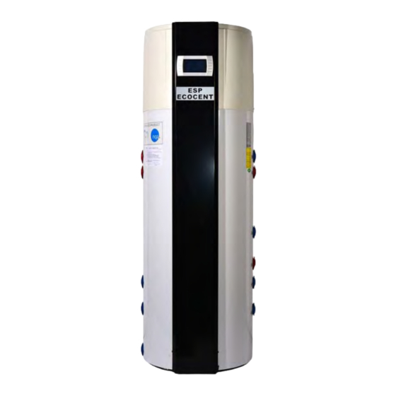
5.0 Specifications: 5.1 Appearance: Air Inlet Air Outlet Controller Water Storage Tank Good Looking and Efficient The attractive design allows the unit to be placed in the open in finished utility spaces and basements; depending on ambient conditions, the cost of operation can be up to 75% less of that of an electric water heater, and can be used in locations unsuitable for solar hot water heating. -
Page 12: Dimensions
5.2 Dimensions: 200L Ecocent Dimension (mm) 1705 1050 Ø 560 8of 36 ESP400-10-200L and 300L... - Page 13 300L Ecocent Dimension (mm) 1820 1180 PLEASE NOTE: The Ecocent is supplied with 2 Secondary Coils. 9of 36 ESP400-10-200L and 300L...
-
Page 14: Performance
5.3 Performance: Units ESP400-010-200l(D) ESP400-010-300l(D) Heating Capacity Water Tank Capacity Power input 0.64 0.64 Running Current 2.78 2.78 Power Supply 230v/50hZ 230v/50hZ Number of Compressors Compressor Type Rotary Rotary Rated Outlet Temp °C Air Volume Air Pressure Duct Diameter Noise dB(A) Water Connection Size inch... -
Page 15: Dhw Recovery Times
5.4 DHW Recovery times: The recovery time of your Ecocent (the time it takes to return to fully hot) depends on the storage temperature (normally 55°C), the temperature of your cold water supply (normally taken to be 10°C), the temperature of the air supply (at least 15°C) and the amount of water you use. -
Page 16: Installation
maximised through careful design and heat use planning. The supplier/installer of your Ecocent unit should always be prepared to assist you with this. 6.0 INSTALLATION 6.1 INSTALLATION DIAGRAM: Unless requested, air ducting not supplied, because we don’t know how much will be required for your particular project Where the unit is installed to draw in air, or dispose of air, from sites more than 8mtrs from the unit a... -
Page 17: Drain-Off Cock
outlet on the combination group valve. The Cold Water Combination Valve can be installed as a complete one piece unit. The valve incorporates a factory set, non-adjustable Pressure Reducer/ Strainer, an Expansion Valve connection a single Check Valve and balanced cold feed. The valve can be fitted in any orientation to suit the installation, however, ensure that the valve is installed with the direction of flow arrows (stamped on the side of the brass body) pointing towards the unit (in the direction of the flow of water). -
Page 18: Warnings
Whilst secondary returns do make for greater comfort by having hot water immediately available at taps, it is an energy sapping facility – it is recommended that all secondary returns should be fitted with timers so that circulation is not constant. PLEASE NOTE: All secondary return pipework MUST be very well insulated and, even then, may have a very detrimental impact upon the economics of generating hot water. -
Page 19: Discharge Pipe Work
v) For units with secondary coil facilities, please discuss the use of the coil, and a suitable configuration for use, with a suitably qualified plumber/engineer before proceeding to add a heat source to the secondary coil. 6.11 Discharge Pipe Work: It is a requirement of Building Regulations that any discharge from an unvented system is conveyed to where it is visible, but will not cause danger to persons in or about the building. -
Page 20: How To Connect To The Heat Pump
Note: The discharge will consist of very high temperature water and steam. Asphalt, roofing felt and non-metallic rainwater goods may be damaged by such discharges and you must take this in to account when fitting the unit. Should such damage be caused, ESP will accept no liability for any consequent damage so caused. -
Page 21: Vacuum And Filling Refrigerants
PLEASE NOTE that only manufacturer approved engineers should carry out any work on the heat pump. Call the manufacturer for the name of an approved engineer in your area. THE FOLLOWING SECTIONS (7.1 TO 7.5 INCLUSIVE) ARE FOR REFRIGERATION ENGINEERS ONLY: 7.1 Vacuum and filling Refrigerants: The unit is supplied pre-gassed. -
Page 22: Controller System Test
7.2 Controller System Test: Switch on the power to the unit, check the display of the controller – it will display the water temperature when the unit is in standby mode. If the controller display is showing an incorrect reading or an error code, please refer to Section 10. -
Page 23: Earthing
The unit MUST be earthed and a facility is provided for this in the unit Design. You must have the unit fitted by a suitably qualified installer – ESP Accepts no responsibility for units that are not fitted by fully qualified engineers Also, failure to have the unit fitted by a suitably qualified installer will invalidate the warranty/guarantee of the unit. -
Page 24: Operation
8.0 OPERATION 8.1 Control Panel Explanation: Button Symbol Name Function Used to turn the unit on or ① On/Off off and lock the control Used to switch modes or save ② Mode parameters Used to set the clock or ③ Clock timers. -
Page 25: Display Explanation
8.2 Display Explanation: 8.3 Using the control panel: 8.3.1 Turning the unit on or off: Please note. Before the unit is turned on for the first time, you must: 1) Check that the tank is full of water; 2) Check that the unit is correctly wired in to the mains power from a suitable MCB. When the power is turned on to the unit, the first screen is the start-up screen: 21of 36 ESP400-10-200L and 300L... -
Page 26: Mode Selection
Which then changes to show the firmware version: Please note that the version may be different on your unit The unit then displays the stand-by screen: Press the on/off key for 0.5 second, the unit will beep and start and show the following screen: Display when the unit is running Please note that the immersion heater symbol on later models has changed from that in the colour photos... - Page 27 f) Vacation Mode: You can set the unit to start up several months from the current date. When you go on vacation, it allows you to set the unit to run at a preset date and time for your return. Electric Heater mode and Fan modes are discussed further down.
-
Page 28: Setting The Clock
8.3.3 Setting the Clock: The clock can be set in either the standby or running modes. The following example illustrates the procedure when in running mode: Press the clock button once. The time will flash. Press the clock button again and the hour segment will flash. -
Page 29: Setting The Timers
8.3.4 Setting the timers. In heating mode, Eco mode and intelligent mode, two timers can be set to define two periods of water heating. However, setting the timers makes the Ecocent less economic to run. 25of 36 ESP400-10-200L and 300L... - Page 30 To set the timers, press the clock button and hold it for 2 Secs. The “ON 1” symbol to the right of the main display area will start flashing. Pressing the clock button again will cause the hour segment to flash. Adjust this to the required time as if setting the clock (above).
- Page 31 27of 36 ESP400-10-200L and 300L...
-
Page 32: Vacation Mode
To cancel the timers: 8.3.5 Vacation Mode. To set the vacation mode, first select vacation mode as described above then press and hold the clock button for 2 Secs. The “on” symbol and the date segment will flash in the main display area. Set the date as before. Please see the following example: 28of 36 ESP400-10-200L and 300L... -
Page 33: Electric Heating Mode
8.3.6 Electric Heating Mode: Warning. Using this mode will turn the immersion heater on in either standby or heater mode. Pressing the Electric Heater button once will turn the immersion on and pressing it again will turn it off. 29of 36 ESP400-10-200L and 300L... -
Page 34: Fan Mode Settings
8.3.7 Fan mode settings The fan mode can be used for two purposes: The fan speed in heating mode can be set or the fan can be set to run even when the unit is in standby to provide additional ventilation. Press and hold the electric heater button for 2 Secs. -
Page 35: Maintenance Requirements
9.0 MAINTENANCE REQUIREMENTS To ensure the continued optimum performance of the Ecocent, it should be regularly maintained. This is of particular importance in hard water areas or where the water supply contains particulate matter. Maintenance should be carried out by a suitably qualified plumber/engineer and any replacement parts used must only be supplier recommended spare parts. -
Page 36: Refilling The System
terminations on the element. Rewire the immersion heater. Close and secure terminal cover then the refill the unit. 9.5 Refilling the System: DO NOT switch on the immersion heater(s) or heat pump part of the unit until the system has been completely refilled. -
Page 37: Warranty
ESP warrants/guarantees the electrical parts, thermal controls and valves relating to the cylinder for a period of one year from the date of purchase, with the exception of normal wear and tear including any damage caused as a result of lime scale deposits. -
Page 38: Environmental Information
This warranty/guarantee is not valid for installations outside the United Kingdom or the Republic of Ireland. Any warranty/guarantee is for replacement parts only. The purchaser of the unit acknowledges that he/she has seen ESP’s conditions of supply and has understood them. - Page 39 13.1 Exploded diagram The following diagram shows all of the parts of the Ecocent. The numbers correspond to the table below that names all parts in case spares are ever required: Number Components Name Water Tank Electronic Box Supporting Plate Terminal Base Wire Controller Transformer...
-
Page 40: Appendix 1. Pcb Layouts
Appendix 1 – PCB Layouts Definition of the Ports OUT1 Compressor (Output)(220-230VAC) OUT2 Heater (Output)(220-230VAC) OUT3 Two Way Valve(Output)(220-230VAC) OUT4 High Speed Fan(Output)(220-230VAC) OUT 5 Low Speed Fan/Circulation Fan/Circulation Pump/Recovery Pump/Cooling (Output)(220-230VAC) AC-N Ground NET GND 12V Remote Controller DIO 1 GND Remote ON/Off DIO 2 GND Over Heat Protection...
Need help?
Do you have a question about the Ecocent 200L and is the answer not in the manual?
Questions and answers
Can the Ecocent extract rate be raised to reduce condensation in a bathroom
The ESP Ecocent 200L does not have an adjustable extract rate specifically mentioned to reduce condensation in a bathroom. However, it draws air/heat/moisture from areas like bathrooms and uses a smaller motor than typical extractor fans, operating at a lower system pressure differential. This process effectively reduces the need for a separate extractor fan, which may help with condensation, but there is no direct indication that the extract rate can be increased for this purpose.
This answer is automatically generated