Table of Contents
Advertisement
Quick Links
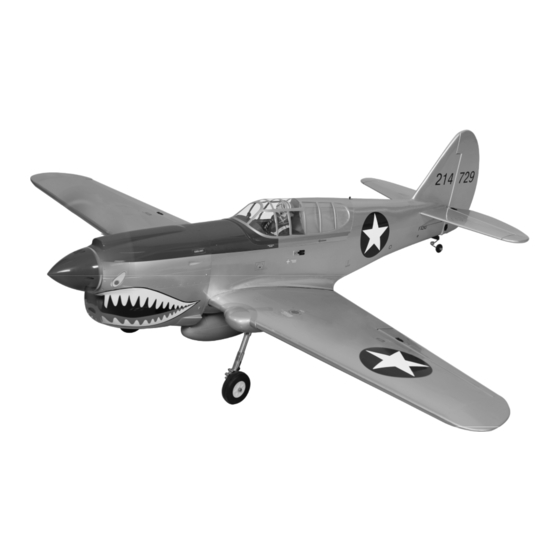
P40 WARHAWK
GP/EP 30/35cc SCALE 1:4 ¾ ARF
SPECIFICATION
- Wingspan: 2040mm (80.3in)
- Length: 1797mm (70.7 in)
- Flying weight: 6600-7500 g
- Wing area: 76 dm2
- Wing loading: 95g/dm2
- Wing type: Naca airfoils
- Retract gear type: Air-retract With CNC
Suspension Metal Struts (included)
- Spinner size: 120mm (included)
- Pressure for air tank retract: 7 bar (100 PSI)
- Radio: 8 channel radio system minimum.
9 standard hi-torque servo: 2 aileron; 2 flap
2 elevator; 1 rudder; 1 throttle; 1 air valve
control (not included)
- Engine: 30/35cc gas engine (not included)
- Motor: brushless outrunner 2500 W,
250 KV (not included)
- Recommended receiver battery:
6.0V 2400/2600mAh NiMH (not included)
Instruction Manual
- Propeller: suit with your engine
- Gravity CG: 120 mm (4.7 in) Back from the
leading edge of the wing, at the fuselage
- Control throw Ailerons: Low: 13mm up/down,
10% expo; High: 15mm up/down, 10% expo
- Control throw Elevators: Low: 13mm up/down,
12% expo; High: 15mm up/down, 12% expo
- Control throw Rudder: Low: 30mm right/left,
15% expo; High: 45mm right/left, 15% expo
- Control throw Flaps: Mid: 15mm down;
Landing: 25mm down
- Experience level: Intermediate
- Plane type: scale military
RECOMMENDED MOTOR AND BATTERY SET UP
- Motor: RIMFIRE 1.60 (not included)
- Lipo cell: 12 cells / 5000 – 6000mAh (not included)
- Esc: 120-160A (not included)
GP
EP
version
version
Advertisement
Table of Contents

Related Manuals for Phoenix P40 WARHAWK


Summary of Contents for Phoenix P40 WARHAWK
- Page 1 Instruction Manual version version P40 WARHAWK GP/EP 30/35cc SCALE 1:4 ¾ ARF SPECIFICATION - Propeller: suit with your engine - Wingspan: 2040mm (80.3in) - Length: 1797mm (70.7 in) - Gravity CG: 120 mm (4.7 in) Back from the - Flying weight: 6600-7500 g...
- Page 2 Please trial fit all the parts. Make sure you have the correct parts and that they fit and are aligned properly before gluing! This will assure proper assembly. The P40 WARHAWK GP/EP 30/35cc SCALE 1:4 ¾ ARF is hand made from natural materials, every plane is unique and minor adjustments may have to be made.
- Page 3 P40 WARHAWK Instruction Manual < Bottom view > Main Wing Aileron Flap Ensure smooth, non-binding movement when assembling Make certain the hinges are adequately secured with glue. If they come loose in flight accidents may result. Secure nylon hinges with instant glue, being careful not to glue the wing and airleron together.
- Page 4 P40 WARHAWK Instruction Manual Aileron Flap Aileron and Flap Servo approx. 13mm 1.5mm 1.5mm Cut away film only. here Supplied with the servo Must be purchased separately! Assemble left and right sides the same way Cut off shaded portion Pay close attention here!
- Page 5 P40 WARHAWK Instruction Manual 2x10mm 2x10mm Warning! Set all scerws securely. If they come off during flight you will lose control of your aircraft! 2x10mm Tie the string. Pull out servo cord with string.
-
Page 6: Installing The Ailerons And Flaps Linkages
P40 WARHAWK Instruction Manual INSTALLING THE AILERONs AND FLAPs LINKAGES 3 x 12mm Screw Neutral Nylon Nut 3mm Washer 3 x 30mm Cap Screw 3x30mm Aluminum ball 3 x 25mm Cap Screw 3 x 55mm Push rod Aileron Flap < Bottom view >... - Page 7 P40 WARHAWK Instruction Manual 3x12mm < Bottom view > Apply threadlocker (screw cement). Cut off shaded portion Assemble left and right sides the same way...
-
Page 8: Installing The Main Landing Gear
P40 WARHAWK Instruction Manual INSTALLING THE MAIN LANDING GEAR 5 x 45mm Cap Screw 4x4mm 10 x 8mm Collar 4x4mm Set Screw Apply threadlocker (screw cement). - Page 9 P40 WARHAWK Instruction Manual...
-
Page 10: Superlock Air Retracts
P40 WARHAWK Instruction Manual SUPERLOCK AIR RETRACTS AIR PUMP VALUE ONE WAY MAIN GEAR 3 WAY CONNECTOR VALVE CONTROL 3 WAY CONNECTOR MAIN GEAR AIR TANK SERVO 3 WAY CONNECTOR... - Page 11 P40 WARHAWK Instruction Manual 4 x 30mm Cap Screw 4mm Washer 4mm Spring Washer 4x30mm Assemble left and right sides the same way Cut off shaded portion Pay close attention here! < Wheel well > Cut off shaded portion Pay close attention here!
- Page 12 P40 WARHAWK Instruction Manual Assemble left and right sides the same way Apply epoxy glue 27mm Cut away Cut away 27mm...
- Page 13 P40 WARHAWK Instruction Manual Remove the covering Apply epoxy glue Cut off shaded portion...
- Page 14 P40 WARHAWK Instruction Manual SECURE The bomb 4 x 20mm Cap Screw 4mm Spring Washer 4mm Washer 4x20mm Cap screw...
-
Page 15: Horizontal Stabilizer Installation
P40 WARHAWK Instruction Manual SECURE The Wing To The Fuselage Attach the wings to the joiner tube and secure the wing panels to the fuselage. Cap screw for main wing fixture Cut off shaded portion Assemble left and right sides the same way. - Page 16 P40 WARHAWK Instruction Manual Cut off shaded portion Warning! Cut away film only here Make certain plane is aligned accurately per the diagram. A mis-aligned plane can fly erraticaliy and cause accidents. Secure nylon hinges with instant glue, being careful tail wing and elevator.
-
Page 17: Installing Rudder And Tail Gear
P40 WARHAWK Instruction Manual INSTALLING ruDDER AND TAIL GEAR 3 x 15mm TP Screw 3 x 4mm Set Screw 2.7mm Collar 3x4mm 2.7mm 3x15mm TP Secure nylon hinges with instant glue, being careful vertical fin and rudder. Align the center line of vertical fin with rudder. -
Page 18: Installing The Rudder Pushrod
P40 WARHAWK Instruction Manual 8. Plug the rudder servo into the receiver and center INSTALLING THE RUDDER PUSHROD the servo. Install the servo arm onto the servo. 1. Locate the pushrod exit slot on the right side of the 9. Center the rudder and hold it in place using a piece fuselage. - Page 19 P40 WARHAWK Instruction Manual Set all screws securely. If they come off during flight you will lose control of your aircraft! Must be purchased separately! Cut off shaded portion...
-
Page 20: Installing The Elevator Pushrod
P40 WARHAWK Instruction Manual Cut off excess. Pay close attention here INSTALLING THE ELEVATOR PUSHROD 7. Attach nylon clevis to the control horn and secure it . 8. Locate one nylon servo arm, and using wire cutters, 1. Locate the pushrod exit slot on the right side and left remove all but one of the arms. - Page 21 P40 WARHAWK Instruction Manual 2x10mm 3x20mm approx. 13mm Must be purchased separately! Assemble left and right Cut off excess. sides the same way Pay close attention here Cut off shaded portion...
-
Page 22: Installing The Air Valve
P40 WARHAWK Instruction Manual INSTALLING THE AIR VALVE Loosen nut. - Page 23 P40 WARHAWK Instruction Manual Nylon Strap Tighten firmly. Air Hose Air Hose Air Hose...
- Page 24 P40 WARHAWK Instruction Manual Air Tank Air Hose Air Hose Air Hose Air Hose Use linkage to push the piston in all the way. Keep the piston inside the - marked area. Air flow direction.
-
Page 25: Installing The Fuel Tank
P40 WARHAWK Instruction Manual INSTALLING THE Fuel Tank 5. Test fit the stopper assembly into the tank. It may be necessary to remove some of the 1. The stopper has been pre-assembled at the flashing around the tank opening using a factory. -
Page 26: Installing The Engine
P40 WARHAWK Instruction Manual INSTALLING THE ENGINE 5mm Washer 5mm Spring Washer 3 x 250mm Choke rod 5 x 100mm Cap Screw 3 x 225mm Throttle rod Silicone Throttle 12 x 60mm Aluminum Silicone May be you also need to trim some... - Page 27 P40 WARHAWK Instruction Manual Zip tie DLE 35 CC Zip tie Electronic Ignition System DLE 35 CC Foam Must be purchased separately!
-
Page 28: Installing The Throttle
P40 WARHAWK Instruction Manual Throttle Lever Silicone Silicone Choke Lever INSTALLING THE THROTTLE 1. Plug the throttle servo into the receiver and turn on the radio system. Check to ensure that the throttle servo output shaft is moving in the correct direction. -
Page 29: Mounting The Cowl
P40 WARHAWK Instruction Manual Throttle Servo MOUNTING THE COWL 4. While holding the cowl firmly in position, drill four 1,6mm pilot holes through both the cowl 1. Remove the muffler and needle valve assembly and the side edges of the firewall. -
Page 30: Installing The Spinner
P40 WARHAWK Instruction Manual Washer 3x15mm INSTALLING THE SPINNER Install the spinner back-plate, propeller and spinner cone. The spinner cone is held in place using two screws. The propeller should not touch any part of the spinner cone. If it dose, use a sharp modeling knife and carefully trim away the spinner cone where the propeller comes in contact with it. -
Page 31: Installing The Receiver And Battery
P40 WARHAWK Instruction Manual Propeller Spinner Spinner Use the spacer suitable for a shaft. 3x10mm Must be purchased separately! INSTALLING THE RECEIVER AND BATTERY INSTALLING THE SWITCH 1. Plug the servo leads and the switch lead into the 1. The switch should be mounted on the fuselage receiver. -
Page 32: Installing The Electric Motor ( Ep Version )
P40 WARHAWK Instruction Manual INSTALLING THE ELECTRIC MOTOR ( EP VERSION ) 4 x 35mm Cap Screw 10x15mm Aluminum HACKER BRUSHLESS Q80 5mm Washer 4mm Washer 4x35mm 10x15mm 4x35mm 4mm Spring Washer White glue 12x60mm 5x100mm 5x100mm Apply threadlocker (screw cement). - Page 33 P40 WARHAWK Instruction Manual Velcro Battery Cord Battery Must be purchased separately! When rotating clock wise, change the connection of 2 wires. < Check the motor rotation >...
-
Page 34: Lateral Balance
P40 WARHAWK Instruction Manual BALANCING 3. Turn the airplane upside down. Place your fingers 1. It is critical that your airplane be balanced correctly. on the masking tape and carefully lift the plane. Improper balance will cause your plane to lose 4. -
Page 35: Flight Preparation Pre Flight Check
P40 WARHAWK Instruction Manual FLIGHT PREPARATION PRE FLIGHT CHECK 13mm 1. Completely charge your transmitter and receiver 13mm batteries before your first day of flying. Aileron Control 2. Check every bolt and every glue joint in your plane to ensure that everything is tight and well bonded. - Page 36 P40 WARHAWK Instruction Manual Main Gear Dimensional Detail 30.0 187.0 16.0 Tail Gear Dimensional Detail 28.0 28.0...
- Page 37 10x15mm 4x35mm 3x15mm(TP) 12x60mm 5x100mm 16x5mm 3x10mm 4x20mm 4x30mm 4x30mm 4x30mm 4x30mm...
- Page 38 3x12mm 3x20mm 3x12mm 3x20mm 3x12mm 3x12mm 3x30mm 3x25mm 2x10mm(TP) 2x10mm(TP) 3x25mm 3x4mm 3x12mm 3x15mm(TP) 3x25mm 3x12mm 3x12mm 3x12mm 3x30mm 2x10mm(TP) 2x10mm(TP)
- Page 39 I/C FLIGHT WARNINGS Always operate in open areas, away Keep all onlookers (especially small from factories, hospitals, schools, THE PROPELLER IS DANGEROUS children and animals) well back from buildings and houses etc. NEVER fly Keep fingers, clothing (ties, shirt the area of operation. This is a flying your aircraft close to people or built sleeves, scarves) or any other loose aircraft, which will cause serious...
- Page 40 I/C FLIGHT GUIDELINES Operate the control sticks on the When ready to fly, first extend the transmitter and check that the control transmitter aerial. surfaces move freely and in the ALWAYS land the model INTO the CORRECT directions. wind, this ensures that the model lands at the slowest possible speed.
Need help?
Do you have a question about the P40 WARHAWK and is the answer not in the manual?
Questions and answers