Table of Contents
Advertisement
Advertisement
Table of Contents

Related Manuals for ASROCK Z270 SUPERCARRIER


Summary of Contents for ASROCK Z270 SUPERCARRIER
-
Page 2: Copyright Notice
(including damages for loss of profits, loss of business, loss of data, interruption of business and the like), even if ASRock has been advised of the possibility of such damages arising from any defect or error in the documentation or product. - Page 3 If you require assistance please call ASRock Tel : +886-2-28965588 ext.123 (Standard International call charges apply) The terms HDMI™...
-
Page 4: Table Of Contents
Contents Chapter 1 Introduction Package Contents Specifications Motherboard Layout I/O Panel WiFi-802.11ac Module and ASRock WiFi 2.4/5 GHz Antenna Chapter 2 Installation Installing the CPU Installing the CPU Fan and Heatsink Installing Memory Modules (DIMM) Expansion Slots (PCI Express Slots) - Page 5 2.10.4 Driver Installation and Setup 2.11 M.2_SSD (NGFF) Module Installation Guide Chapter 3 Software and Utilities Operation Installing Drivers A-Tuning ASRock Live Update & APP Shop 3.3.1 UI Overview 3.3.2 Apps 3.3.3 BIOS & Drivers 3.3.4 Setting Enabling USB Ports for Windows® 7 Installation...
- Page 6 4.6.1 CPU Configuration 4.6.2 Chipset Configuration 4.6.3 Storage Configuration 4.6.4 Intel® Thunderbolt™ 4.6.5 Super IO Configuration 4.6.6 ACPI Configuration 4.6.7 USB Configuration 4.6.8 Trusted Computing Tools Hardware Health Event Monitoring Screen Security Screen 4.10 Boot Screen 4.11 Exit Screen...
-
Page 7: Chapter 1 Introduction
ASRock’s website without further notice. If you require technical support related to this motherboard, please visit our website for specific information about the model you are using. You may find the latest VGA cards and CPU support list on ASRock’s website as well. ASRock website http://www.asrock.com. -
Page 8: Specifications
• 4 x DDR4 DIMM Slots • Supports DDR4 3733+(OC)*/3600(OC)/3200(OC)/2933 (OC)/2800 (OC)/2400**/2133 non-ECC, un-buffered memory * Please refer to Memory Support List on ASRock's website for more information. (http://www.asrock.com/) ** 7 Gen Intel® CPU supports DDR4 up to 2400; 6 Gen Intel®... - Page 9 Z270 SuperCarrier • Supports NVIDIA® Quad SLI , 4-Way SLI , 3-Way SLI and SLI • 1 x Vertical M.2 Socket (Key E) with the bundled WiFi- 802.11ac module (on the rear I/O) • 15μ Gold Contact in VGA PCIe Slots (PCIE1 and PCIE4) Graphics • Intel®...
- Page 10 • 7.1 CH HD Audio with Content Protection (Realtek ALC1220 Audio Codec) • Premium Blu-ray Audio support • Supports Surge Protection (ASRock Full Spike Protection) • Supports Purity Sound - Nichicon Fine Gold Series Audio Caps - 120dB SNR DAC with Differential Amplifier - TI®...
- Page 11 * Hot Plug is supported on Win 10 only • 1 x Optical SPDIF Out Port • 2 x USB 2.0 Ports (Supports ESD Protection (ASRock Full Spike Protection)) • 4 x USB 3.0 Ports (Supports ESD Protection (ASRock Full Spike Protection))** ** Ultra USB Power is supported on USB3_34 ports.
- Page 12 • 2 x USB 2.0 Headers (Support 4 USB 2.0 ports) (Intel® Z270) (Supports ESD Protection (ASRock Full Spike Protection)) • 2 x USB 3.0 Headers (Support 4 USB 3.0 ports) (ASMedia ASM1074 hub) (Supports ESD Protection (ASRock Full Spike Protection)) • 1 x Vertical Type A USB 3.0 (Intel® Z270) • 1 x Dr.
-
Page 13: Installation
* To install Windows® 7 OS, a modified installation disk with xHCI drivers packed into the ISO file is required. Please refer to page 56 for more detailed instructions. * For the updated Windows® 10 driver, please visit ASRock’s website for details: http://www.asrock.com Certifica- • FCC, CE, WHQL... -
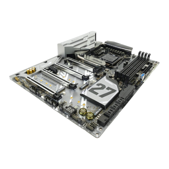
Page 14: Motherboard Layout
1.3 Motherboard Layout ATX12V1 CPU_FAN1 CPU_OPT/W_PUMP CLRBTN1 M2_WIFI_1 Top: RJ-45 Top: RJ-45 Top: USB 3.0 RJ-45 T: USB3 B: USB4 5GLAN PCIE1 CMOS Battery PCIE2 Intel Z270 PCIE3 PCIE4 Z270 SUPER CARRIER BIOS PCIE5 RSTBTN1 PWRBTN1 SPK_PLED1 BIOS_A_LED1 CHA_FAN3/W_PUMP CHA_FAN1/W_PUMP COM1 CHA_FAN2/W_PUMP PLED PWRBTN... - Page 15 Z270 SuperCarrier No. Description ATX 12V Power Connector (ATX12V1) CPU Fan / Waterpump Fan Connector (CPU_OPT/W_PUMP) CPU Fan Connector (CPU_FAN1) 2 x 288-pin DDR4 DIMM Slots (DDR4_A1, DDR4_B1) 2 x 288-pin DDR4 DIMM Slots (DDR4_A2, DDR4_B2) XMP Switch (XMP_ON1) ATX Power Connector (ATXPWR1) Vertical Type A USB 3.0 (USB3_9)
-
Page 16: I/O Panel
1.4 I/O Panel No. Description No. Description USB 2.0 Ports (USB12) Optical SPDIF Out Port DisplayPort 1.2 USB 3.0 Ports (USB3_34)**** LAN RJ-45 Port (Intel® I211AT)* USB 3.0 Port (USB3_2) LAN RJ-45 Port (Intel® I219V)* Intel® Thunderbolt 3 (TB_2) 5G LAN RJ-45 Port (AQUANTIA® USB 3.0 Port (USB3_1) AQC108)** Central / Bass (Orange) - Page 17 Z270 SuperCarrier ** There are two LEDs on each 5G LAN port. Please refer to the table below for the 5G LAN port LED indications. ACT/LINK LED SPEED LED 5G LAN Port Activity / Link LED Speed LED Status Description...
- Page 18 How to Remove the I/O Cover? Certain graphics cards with extra thickness of the back plate may collide with the pre-installed I/O cover. Before installing such a wider graphics card, please loosen the screws to remove the I/O cover, as the picture shown below.
-
Page 19: Wifi-802.11Ac Module And Asrock Wifi 2.4/5 Ghz Antenna
Z270 SuperCarrier 1.5 WiFi-802.11ac Module and ASRock WiFi 2.4/5 GHz Antenna WiFi-802.11ac + BT Module This motherboard comes with an exclusive WiFi 802.11 a/b/g/n/ac + BT v4.0 module (pre-installed on the rear I/O panel) that offers support for WiFi 802.11 a/b/ g/n/ac connectivity standards and Bluetooth v4.0. - Page 20 WiFi Antennas Installation Guide Step 1 Prepare the WiFi 2.4/5 GHz Antennas that come with the package. Step 2 Connect the two WiFi 2.4/5 GHz Antennas to the antenna connectors. Turn the antenna clock- wise until it is securely connected. Step 3 Set the WiFi 2.4/5 GHz Antenna as shown in the illustration.
-
Page 21: Chapter 2 Installation
Z270 SuperCarrier Chapter 2 Installation This is an ATX form factor motherboard. Before you install the motherboard, study the configuration of your chassis to ensure that the motherboard fits into it. Pre-installation Precautions Take note of the following precautions before you install motherboard components or change any motherboard settings. -
Page 22: Installing The Cpu
2.1 Installing the CPU 1. Before you insert the 1151-Pin CPU into the socket, please check if the PnP cap is on the socket, if the CPU surface is unclean, or if there are any bent pins in the socket. Do not force to insert the CPU into the socket if above situation is found. Otherwise, the CPU will be seriously damaged. - Page 23 Z270 SuperCarrier...
- Page 24 Please save and replace the cover if the processor is removed. The cover must be placed if you wish to return the motherboard for after service.
-
Page 25: Installing The Cpu Fan And Heatsink
Z270 SuperCarrier 2.2 Installing the CPU Fan and Heatsink... -
Page 26: Installing Memory Modules (Dimm)
2.3 Installing Memory Modules (DIMM) This motherboard provides four 288-pin DDR4 (Double Data Rate 4) DIMM slots, and supports Dual Channel Memory Technology. 1. For dual channel configuration, you always need to install identical (the same brand, speed, size and chip-type) DDR4 DIMM pairs. 2. - Page 27 Z270 SuperCarrier...
-
Page 28: Expansion Slots (Pci Express Slots)
2.4 Expansion Slots (PCI Express Slots) There are 5 PCI Express slots on the motherboard. Before installing an expansion card, please make sure that the power supply is switched off or the power cord is unplugged. Please read the documentation of the expansion card and make necessary hardware settings for the card before you start the installation. -
Page 29: Jumpers Setup
Z270 SuperCarrier 2.5 Jumpers Setup The illustration shows how jumpers are setup. When the jumper cap is placed on the pins, the jumper is “Short”. If no jumper cap is placed on the pins, the jumper is “Open”. The illustration shows a 3-pin jumper whose pin1 and pin2 are “Short”... -
Page 30: Onboard Headers And Connectors
2.6 Onboard Headers and Connectors Onboard headers and connectors are NOT jumpers. Do NOT place jumper caps over these headers and connectors. Placing jumper caps over the headers and connectors will cause permanent damage to the motherboard. System Panel Header Connect the power PLED+ PLED-... - Page 31 Z270 SuperCarrier Power LED and Speaker Please connect the SPEAKER DUMMY Header chassis power LED and DUMMY (7-pin SPK_PLED1) the chassis speaker to this (see p.8, No. 18) header. PLED+ PLED+ PLED- Serial ATA3 Connectors These ten SATA3 (SATA_EXP0_1: connectors support SATA see p.8, No.
- Page 32 USB 2.0 Headers There are two headers USB_PWR (9-pin USB3_4 on this motherboard. (see p.8, No. 23) DUMMY Each USB 2.0 header can (9-pin USB5_6) support two ports. (see p.8, No. 22) USB_PWR USB 3.0 Headers There are two headers Vbus Vbus Vbus...
- Page 33 Z270 SuperCarrier Chassis Optional/Water This motherboard Pump Fan Connector provides two 4-Pin water (4-pin CHA_FAN1/W_ cooling chassis fan PUMP) connectors. If you plan to FAN_SPEED FAN_VOLTAGE_CONTROL (see p.8, No. 25) FAN_SPEED_CONTROL connect a 3-Pin chassis (4-pin CHA_FAN2/W_ water cooler fan, please PUMP) connect it to Pin 1-3.
- Page 34 ATX 12V Power This motherboard pro- Connector vides a 8-pin ATX 12V (8-pin ATX12V1) power connector. To use a (see p.8, No. 1) 4-pin ATX power supply, please plug it along Pin 1 and Pin 5. Graphics 12V Power This motherboard pro- Connector vides a 6-pin Graphics (6-pin GFX_12V1)
-
Page 35: Smart Switches
Z270 SuperCarrier 2.7 Smart Switches The motherboard has four smart switches: Power Switch, Reset Switch, Clear CMOS Switch and XMP Switch. Power Switch Power Switch allows users (PWRBTN1) to quickly turn on/off the Power (see p.8, No. 17) system. Reset Switch... -
Page 36: Dr. Debug
2.8 Dr. Debug Dr. Debug is used to provide code information, which makes troubleshooting even easier. Please see the diagrams below for reading the Dr. Debug codes. Code Description Please check if the CPU is installed correctly and then clear CMOS. - Page 37 Z270 SuperCarrier Problem related to USB devices. Please try removing all USB devices. Problem related to memory. Please re-install the CPU and memory then clear CMOS. If the problem still exists, please install only one memory module or try using other memory modules.
-
Page 38: Sli Tm
2.9 SLI , 3-Way SLI , 4-Way SLI and Quad SLI Operation Guide This motherboard supports NVIDIA® SLI , 3-way SLI , 4-way SLI and Quad (Scalable Link Interface) technology that allows you to install up to four identical PCI Express x16 graphics cards. Requirements 1. - Page 39 Z270 SuperCarrier Step 3 Align and insert the ASRock SLI_HB_ Bridge_3S Card (if you install NVIDIA® high-bandwidth graphics cards) or ASRock Flexible SLI Bridge Connector Cable to the goldfingers on each graphics card. Make sure the ASRock SLI_HB_Bridge_3S Card or ASRock Flexible SLI Bridge Connector Cable is firmly in place.
-
Page 40: Installing Three Sli Tm -Ready Graphics Cards
PCI Express graphics card are connected. Repeat this step on the three graphics cards. Step 3 Align and insert the ASRock 3-Way SLI Bridge Card to the goldfingers on each graphics card. Make sure the ASRock 3-Way SLI Bridge Card is firmly in place. - Page 41 Z270 SuperCarrier Step 4 Connect a VGA cable or a DVI cable to the monitor connector or the DVI connector of the graphics card that is inserted to PCIE1 slot.
-
Page 42: Installing Four Sli Tm -Ready Graphics Cards
Repeat this step on the three graphics cards. Step 3 Align and insert the ASRock 4-Way SLI-S111 Bridge Card to the goldfingers on each graphics card. Make sure the ASRock 4-Way SLI-S111 Bridge Card is firmly in place. ASRock 4-Way SLI-S111 Bridge Card... - Page 43 Z270 SuperCarrier Step 4 Connect a VGA cable or a DVI cable to the monitor connector or the DVI connector of the graphics card that is inserted to PCIE1 slot.
-
Page 44: Driver Installation And Setup
2.9.4 Driver Installation and Setup Install the graphics card drivers to your system. After that, you can enable the Multi-Graphics Processing Unit (GPU) in the NVIDIA® nView system tray utility. Please follow the below procedures to enable the multi-GPU. Step 1 Double-click the NVIDIA Control Panel icon in the Windows®... -
Page 45: Tm , 4-Way Crossfirex Tm And Quad Crossfirex
Z270 SuperCarrier 2.10 CrossFireX , 3-Way CrossFireX , 4-Way CrossFireX Quad CrossFireX Operation Guide This motherboard supports CrossFireX , 3-way CrossFireX , 4-way CrossFireX and Quad CrossFireX that allows you to install up to four identical PCI Express x16 graphics cards. -
Page 46: Installing Three Crossfirex
Step 3 Connect a VGA cable or a DVI cable to the monitor connector or the DVI connec- tor of the graphics card that is inserted to PCIE1 slot. 2.10.2 Installing Three CrossFireX -Ready Graphics Cards Step 1 Insert one graphics card into PCIE1 slot, another graphics card to PCIE2 slot, and the other graphics card to PCIE4 slot. -
Page 47: Installing Four Crossfirex Tm -Ready Graphics Cards
Z270 SuperCarrier 2.10.3 Installing Four CrossFireX -Ready Graphics Cards Step 1 Insert one graphics card into PCIE1 slot, another graphics card into PCIE2 slot, the third graphics card into PCIE4 slot and the last graphics card into PCIE5 slot. Make sure that the cards are properly seated on the slots. -
Page 48: Driver Installation And Setup
2.10.4 Driver Installation and Setup Step 1 Power on your computer and boot into OS. Step 2 Remove the AMD drivers if you have any VGA drivers installed in your system. The Catalyst Uninstaller is an optional download. We recommend using this utility to uninstall any previously installed Catalyst drivers prior to installation. -
Page 49: M.2_Ssd (Ngff) Module Installation Guide
Z270 SuperCarrier 2.11 M.2_SSD (NGFF) Module Installation Guide The M.2, also known as the Next Generation Form Factor (NGFF), is a small size and versatile card edge connector that aims to replace mPCIe and mSATA. The Ultra M.2 Socket (M2_1, M2_2 and M2_3) supports SATA3 6.0 Gb/s module and M.2 PCI Express module up to Gen3 x4 (32 Gb/s). - Page 50 Step 3 Move the standoff based on the module type and length. The standoff is placed at the nut location D by default. Skip Step 3 and 4 and go straight to Step 5 if you are going to use the default nut. Otherwise, release the standoff by hand.
- Page 51 Z270 SuperCarrier M.2_SSD (NGFF) Module Support List Vendor Size Interface Length ADATA 128GB SATA3 2280 AXNS381E-128GM-B ADATA 256GB SATA3 2280 AXNS381E-256GM-B ADATA 32GB SATA3 2230 AXNS330E-32GM-B Crucial 120GB SATA3 2280 CT120M500SSD4 Crucial 240GB SATA3 2280 CT240M500SSD4 Intel 80GB SATA3 2280...
-
Page 52: Chapter 3 Software And Utilities Operation
Chapter 3 Software and Utilities Operation 3.1 Installing Drivers The Support CD that comes with the motherboard contains necessary drivers and useful utilities that enhance the motherboard’s features. Running The Support CD To begin using the support CD, insert the CD into your CD-ROM drive. The CD automatically displays the Main Menu if “AUTORUN”... -
Page 53: A-Tuning
Z270 SuperCarrier 3.2 A-Tuning A-Tuning is ASRock’s multi purpose software suite with a new interface, more new features and improved utilities. 3.2.1 Installing A-Tuning A-Tuning can be downloaded from ASRock Live Update & APP Shop. After the installation, you will find the icon “A-Tuning“ on your desktop. Double-click the “A- Tuning“... -
Page 54: System Info
OC Tweaker Configurations for overclocking the system. System Info View information about the system. *The System Browser tab may not appear for certain models. - Page 55 Configure up to five different fan speeds using the graph. The fans will automatically shift to the next speed level when the assigned temperature is met. Settings Configure ASRock A-Tuning. Click to select "Auto run at Windows Startup" if you want A-Tuning to be launched when you start up the Windows operating system.
-
Page 56: Asrock Live Update & App Shop
Double-click on your desktop to access ASRock Live Update & APP Shop utility. *You need to be connected to the Internet to download apps from the ASRock Live Update & APP Shop. 3.3.1 UI Overview Category Panel Hot News... -
Page 57: Apps
Z270 SuperCarrier 3.3.2 Apps When the "Apps" tab is selected, you will see all the available apps on screen for you to download. Installing an App Step 1 Find the app you want to install. The most recommended app appears on the left side of the screen. The other various apps are shown on the right. - Page 58 Step 3 If you want to install the app, click on the red icon to start downloading. Step 4 When installation completes, you can find the green "Installed" icon appears on the upper right corner. To uninstall it, simply click on the trash can icon *The trash icon may not appear for certain apps.
- Page 59 Z270 SuperCarrier Upgrading an App You can only upgrade the apps you have already installed. When there is an available new version for your app, you will find the mark of "New Version" appears below the installed app icon. Step 1 Click on the app icon to see more details.
-
Page 60: Bios & Drivers
3.3.3 BIOS & Drivers Installing BIOS or Drivers When the "BIOS & Drivers" tab is selected, you will see a list of recommended or critical updates for the BIOS or drivers. Please update them all soon. Step 1 Please check the item information before update. Click on to see more details. -
Page 61: Setting
Z270 SuperCarrier 3.3.4 Setting In the "Setting" page, you can change the language, select the server location, and determine if you want to automatically run the ASRock Live Update & APP Shop on Windows startup. -
Page 62: Enabling Usb Ports For Windows® 7 Installation
Requirements A Windows® 7 installation disk or USB drive • A Windows® PC • Win7 USB Patcher (included in the ASRock Support CD or downloaded from • website) Scenarios You have an ODD and PS/2 ports: If there is an optical disc drive, PS/2 ports and PS/2 Keyboard or mouse on your computer, you can skip the instructions below and go ahead to install Windows®... - Page 63 Z270 SuperCarrier Instructions Step 1 Insert the Windows® 7 installation disk or USB drive to your system. Step 2 Extract the tool (Win7 USB Patcher) and launch it. Step 3 Select how you want to install Windows 7 later. Step 4...
- Page 64 Step 5 Select the USB storage, compact disk or destination folder for the new Windows 7 installation file. Step 6 Click “Start” to begin. Step 7 Now you are able to install Windows® 7 on Intel® new processors with the new burned CD. Or please use the patched ISO image to make an OS USB drive to install the OS.
-
Page 65: Asrock Aura Rgb Led
Z270 SuperCarrier 3.5 ASRock AURA RGB LED ASRock AURA RGB LED allows you to build your own colorful lighting system. By connecting LED strip, you can adjust the RGB LED color through ASRock AURA RGB LED utility. Drag the tab to customize your preference. -
Page 66: Chapter 4 Uefi Setup Utility
Chapter 4 UEFI SETUP UTILITY 4.1 Introduction This section explains how to use the UEFI SETUP UTILITY to configure your system. You may run the UEFI SETUP UTILITY by pressing <F2> or <Del> right after you power on the computer, otherwise, the Power-On-Self-Test (POST) will continue with its test routines. -
Page 67: Ez Mode
Z270 SuperCarrier 4.2 EZ Mode The EZ Mode screen appears when you enter the BIOS setup program by default. EZ mode is a dashboard which contains multiple readings of the system’s current status. You can check the most crucial information of your system, such as CPU speed, DRAM frequency, SATA information, fan speed, etc. -
Page 68: Advanced Mode
4.3 Advanced Mode The Advanced Mode provides more options to configure the BIOS settings. Refer to the following sections for the detailed configurations. To access the EZ Mode, press <F6> or click the "EZ Mode" button at the upper right corner of the screen. -
Page 69: Navigation Keys
Z270 SuperCarrier 4.3.2 Navigation Keys Use < > key or < > key to choose among the selections on the menu bar, and use < > key or < > key to move the cursor up or down to select items, then press <Enter>... -
Page 70: Main Screen
4.4 Main Screen When you enter the UEFI SETUP UTILITY, the Main screen will appear and display the system overview. Favorite Display your collection of BIOS items. Press F5 to add/remove your favorite items. -
Page 71: Oc Tweaker Screen
Z270 SuperCarrier 4.5 OC Tweaker Screen In the OC Tweaker screen, you can set up overclocking features. Because the UEFI software is constantly being updated, the following UEFI setup screens and descriptions are for reference purpose only, and they may not exactly match what you see on your screen. -
Page 72: Bclk Frequency
CPU Configuration Multi Core Enhancement Improve the system's performance by forcing the CPU to perform the highest frequency on all CPU cores simultaneously. Disable to reduce power consumption . CPU Ratio The CPU speed is determined by the CPU Ratio multiplied with the BCLK. Increasing the CPU Ratio will increase the internal CPU clock speed without affecting the clock speed of other components. -
Page 73: Long Duration Maintained
Z270 SuperCarrier Boot Performance Mode Select the performance state that the BIOS will set before OS handoff. Reliability Stress Restrictor Disable or Enable Reliability Stress Restrictor feature. FCLK Frequency Configure the FCLK Frequency. AVX Ratio Offset AVX Ratio Offset specifies a negative offset from the CPU Ratio for AVX workloads. -
Page 74: Dram Configuration
CPU Core Current Limit Configure the current limit of the CPU core. A lower limit can protect the CPU and save power, while a higher limit may improve performance. GT Slice Current Limit Configure the current limit of the GT slice. A lower limit can protect the CPU and save power, while a higher limit may improve performance. - Page 75 Z270 SuperCarrier RAS# to CAS# Delay and Row Precharge (tRCDtRP) O RAS# to CAS# Delay : The number of clock cycles required between the opening of a row of memory and accessing columns within it. Row Precharge: The number of clock cycles required between the issuing of the precharge command and opening the next row.
- Page 76 Read to Precharge (tRTP) The number of clocks that are inserted between a read command to a row pre- charge command to the same rank. Four Activate Window (tFAW) The time window in which four activates are allowed the same rank. CAS Write Latency (tCWL) Configure CAS Write Latency.
- Page 77 Z270 SuperCarrier tRDWR_dd Configure between module read to write delay. tWRRD_sg Configure between module write to read delay. tWRRD_dg Configure between module write to read delay. tWRRD_dr Configure between module write to read delay. tWRRD_dd Configure between module write to read delay.
-
Page 78: Advanced Setting
Configure IO latency for channel A. IO-L (CH B) Configure IO latency for channel B. IO-L Offset (CH A) Configure IO latency offset for channel A. IO-L Offset (CH B) Configure IO latency offset for channel B. RFR Delay (CH A) Configure RFR Delay for Channel A. -
Page 79: Voltage Configuration
Z270 SuperCarrier Dll Bandwidth 0 Configure the Dll Bandwidth 0. Dll Bandwidth 1 Configure the Dll Bandwidth 1. Dll Bandwidth 2 Configure the Dll Bandwidth 2. Dll Bandwidth 3 Configure the Dll Bandwidth 3. Voltage Configuration CPU Vcore Voltage Configure the voltage for the CPU Vcore. - Page 80 PCH PLL Voltage PCH PLL voltage helps BCLK overclocking, also slightly improves memory overclocking. VCCIO Voltage Configure the voltage for the VCCIO. Boot CPU PLL Voltage CPU PLL voltage for BCLK and memory training. CPU PLL volt helps BCLK overclocking, also slightly improves memory overclocking. Setting this voltage higher helps CPU cold bug under LN2 cooling.
- Page 81 Z270 SuperCarrier internal clock during High frequency under Ln2 cooling. For example: 1.020V - 1.125V will be proper value. But the voltage level will be different on each processor. User has to find the best value for your own processor. CPU Vcore Voltage must higher than CPU Internal PLL Voltage, or your processor will hang.
-
Page 82: Advanced Screen
4.6 Advanced Screen In this section, you may set the configurations for the following items: CPU Configuration, Chipset Configuration, Storage Configuration, Intel® Thunderbolt, Super IO Configuration, ACPI Configuration, USB Configuration and Trusted Computing. Setting wrong values in this section may cause the system to malfunction. UEFI Configuration UEFI Setup Style Select the default mode when entering the UEFI setup utility. -
Page 83: Cpu Configuration
Z270 SuperCarrier 4.6.1 CPU Configuration Active Processor Cores Select the number of cores to enable in each processor package. CPU C States Support Enable CPU C States Support for power saving. It is recommended to keep C3, C6 and C7 all enabled for better power saving. -
Page 84: Intel Virtualization Technology
CFG Lock This item allows you to disable or enable the CFG Lock. CPU Thermal Throttling Enable CPU internal thermal control mechanisms to keep the CPU from overheat- ing. Intel Virtualization Technology Intel Virtualization Technology allows a platform to run multiple operating systems and applications in independent partitions, so that one computer system can function as multiple virtual systems. -
Page 85: Chipset Configuration
Z270 SuperCarrier 4.6.2 Chipset Configuration Primary Graphics Adapter Select a primary VGA. Top Of Lower Usable Dram Maximum Value of TOLUD. Dynamic assignment would adjust TOLUD automatically based on largest MMIO length of installed graphic controller. VT-d Intel® Virtualization Technology for Directed I/O helps your virtual machine... - Page 86 PCH PCIE ASPM Support This option enables/disables the ASPM support for all PCH PCIE devices. DMI ASPM Support This option enables/disables the control of ASPM on CPU side of the DMI Link. PCH DMI ASPM Support This option enables/disables the ASPM support for all PCH DMI devices. IOAPIC 24-119 Entries I/O APICs contain a redirection table, which is used to route the interrupts it receives from peripheral buses to one or more local APICs.
-
Page 87: Deep Sleep
Z270 SuperCarrier Deep Sleep Configure deep sleep mode for power saving when the computer is shut down. Restore on AC/Power Loss Select the power state after a power failure. If [Power Off] is selected, the power will remain off when the power recovers. If [Power On] is selected, the system will start to boot up when the power recovers. -
Page 88: Storage Configuration
4.6.3 Storage Configuration SATA Controller(s) Enable/disable the SATA controllers. SATA Controller Speed Indicates the maximum speed the SATA controller can support. SATA Mode Selection AHCI: Supports new features that improve performance. RAID: Combine multiple disk drives into a logical unit. SATA Aggressive Link Power Management SATA Aggressive Link Power Management allows SATA devices to enter a low power state during periods of inactivity to save power. - Page 89 Z270 SuperCarrier ASMedia SATA3 Control IDE: For better compatibility. AHCI: Supports new features that improve performance.
-
Page 90: Intel® Thunderbolt
4.6.4 Intel® Thunderbolt™ Intel(R) Thunderbolt Technology Enable/Disable the Intel(R) Thunderbolt function. Security Level Allows you to choose a security level for the Thunderbolt ports. -
Page 91: Super Io Configuration
Z270 SuperCarrier 4.6.5 Super IO Configuration Serial Port Enable or disable the Serial port. Serial Port Address Select the address of the Serial port. PS2 Y-Cable Enable the PS2 Y-Cable or set this option to Auto. -
Page 92: Acpi Configuration
4.6.6 ACPI Configuration Suspend to RAM Select disable for ACPI suspend type S1. It is recommended to select auto for ACPI S3 power saving. ACPI HEPT Table Enable the High Precision Event Timer for better performance. PS/2 Keyboard Power On Allow the system to be waked up by a PS/2 Keyboard. - Page 93 Z270 SuperCarrier USB Mouse Power On Allow the system to be waked up by an USB mouse.
-
Page 94: Usb Configuration
4.6.7 USB Configuration Legacy USB Support Enable or disable Legacy OS Support for USB 2.0 devices. If you encounter USB compatibility issues it is recommended to disable legacy USB support. Select UEFI Setup Only to support USB devices under the UEFI setup and Windows/Linux operating systems only. -
Page 95: Trusted Computing
Z270 SuperCarrier 4.6.8 Trusted Computing Security Device Support Enable or disable BIOS support for security device. -
Page 96: Tools
4.7 Tools AURA RGB LED ASRock AURA RGB LED allows you to adjust the RGB LED color to your liking. System Browser ASRock System Browser shows the overview of your current PC and the devices connected. UEFI Tech Service Contact ASRock Tech Service if you are having trouble with your PC. Please setup network configuration before using UEFI Tech Service. - Page 97 Save UEFI files in your USB storage device and run Instant Flash to update your UEFI. Internet Flash - DHCP (Auto IP), Auto ASRock Internet Flash downloads and updates the latest UEFI firmware version from our servers for you. Please setup network configuration before using Internet Flash.
-
Page 98: Network Configuration
Secure Backup UEFI Whenever one of the ROM images are outdated or corrupted, switch to the other flash ROM and execute Secure Backup UEFI to duplicate the current working ROM image to the secondary flash ROM. This motherboard has two BIOS chips, an active BIOS (BIOS_A) and a backup BIOS (BIOS_B), which enhances the safety and stability of your system. -
Page 99: Hardware Health Event Monitoring Screen
Z270 SuperCarrier 4.8 Hardware Health Event Monitoring Screen This section allows you to monitor the status of the hardware on your system, including the parameters of the CPU temperature, motherboard temperature, fan speed and voltage. Fan Tuning Measure Fan Min Duty Cycle. - Page 100 CPU Optional Fan Control Mode Select PWM mode or DC mode for CPU Optional fan. CPU Optional Fan Setting Select a fan mode for CPU Optional fan, or choose Customize to set 5 CPU temperatures and assign a respective fan speed for each temperature. CPU Optional Fan Temp Source Select a fan temperature source for CPU Optional fan.
- Page 101 Z270 SuperCarrier Chassis Fan 2 Step Down Set the value of Chassis Fan 1 Step Down. CHA_FAN3 / W_Pump Switch Select CHA_FAN3/CPU Optional or Water Pump mode. Chassis Fan 3 Control Mode Select PWM mode or DC mode for Chassis Fan 3.
-
Page 102: Security Screen
4.9 Security Screen In this section you may set or change the supervisor/user password for the system. You may also clear the user password. Supervisor Password Set or change the password for the administrator account. Only the administrator has authority to change the settings in the UEFI Setup Utility. Leave it blank and press enter to remove the password. -
Page 103: Boot Screen
Z270 SuperCarrier 4.10 Boot Screen This section displays the available devices on your system for you to configure the boot settings and the boot priority. Fast Boot Fast Boot minimizes your computer's boot time. In fast mode you may not boot from an USB storage device. - Page 104 Full Screen Logo Enable to display the boot logo or disable to show normal POST messages. AddOn ROM Display Enable AddOn ROM Display to see the AddOn ROM messages or configure the AddOn ROM if you've enabled Full Screen Logo. Disable for faster boot speed. Boot Failure Guard Message If the computer fails to boot for a number of times the system automatically restores the default settings.
- Page 105 Z270 SuperCarrier Launch Storage OpROM Policy Select UEFI only to run those that support UEFI option ROM only. Select Legacy only to run those that support legacy option ROM only. Select Do not launch to not execute both legacy and UEFI option ROM.
-
Page 106: Exit Screen
4.11 Exit Screen Save Changes and Exit When you select this option the following message, “Save configuration changes and exit setup?” will pop out. Select [OK] to save changes and exit the UEFI SETUP UTILITY. Discard Changes and Exit When you select this option the following message, “Discard changes and exit setup?”... -
Page 107: Contact Information
Contact Information If you need to contact ASRock or want to know more about ASRock, you’re welcome to visit ASRock’s website at http://www.asrock.com; or you may contact your dealer for further information. For technical questions, please submit a support request form at http://www.asrock.com/support/tsd.asp...
Need help?
Do you have a question about the Z270 SUPERCARRIER and is the answer not in the manual?
Questions and answers