Table of Contents
Advertisement
Advertisement
Table of Contents

Related Manuals for ASROCK Z270 Extreme4


Summary of Contents for ASROCK Z270 Extreme4
-
Page 2: Copyright Notice
(including damages for loss of profits, loss of business, loss of data, interruption of business and the like), even if ASRock has been advised of the possibility of such damages arising from any defect or error in the documentation or product. - Page 3 You are also entitled to have the goods repaired or replaced if the goods fail to be of acceptable quality and the failure does not amount to a major failure. If you require assistance please call ASRock Tel : +886-2-28965588 ext.123 (Standard International call charges apply) The terms HDMI™...
-
Page 4: Table Of Contents
Contents Chapter 1 Introduction Package Contents Specifications Motherboard Layout I/O Panel Chapter 2 Installation Installing the CPU Installing the CPU Fan and Heatsink Installing Memory Modules (DIMM) Expansion Slots (PCI Express Slots) Jumpers Setup Onboard Headers and Connectors and Quad SLI Operation Guide 2.7.1 Installing Two SLI -Ready Graphics Cards... - Page 5 Chapter 3 Software and Utilities Operation Installing Drivers A-Tuning 3.2.1 Installing A-Tuning 3.2.2 Using A-Tuning ASRock Live Update & APP Shop 3.3.1 UI Overview 3.3.2 Apps 3.3.3 BIOS & Drivers 3.3.4 Setting Enabling USB Ports for Windows® 7 Installation ASRock AURA RGB LED...
- Page 6 4.6.4 Intel® Thunderbolt™ 4.6.5 Super IO Configuration 4.6.6 ACPI Configuration 4.6.7 USB Configuration 4.6.8 Trusted Computing Tools Hardware Health Event Monitoring Screen Security Screen 4.10 Boot Screen 4.11 Exit Screen...
-
Page 7: Chapter 1 Introduction
If you require technical support related to this mother- board, please visit our website for specific information about the model you are using. You may find the latest VGA cards and CPU support list on ASRock’s website as well. ASRock website http://www.asrock.com. -
Page 8: Specifications
* 3866+(OC) memory frequency can only be achieved when a single memory module is installed (Single channel memory). * Please refer to Memory Support List on ASRock's website for more information. (http://www.asrock.com/) ** 7 Gen Intel® CPU supports DDR4 up to 2400; 6 Gen Intel®... - Page 9 • 7.1 CH HD Audio with Content Protection (Realtek ALC1220 Audio Codec) • Premium Blu-ray Audio support • Supports Surge Protection (ASRock Full Spike Protection) • Supports Purity Sound - Nichicon Fine Gold Series Audio Caps - 120dB SNR DAC with Differential Amplifier - TI®...
- Page 10 - AURA RGB LED • Supports DTS Connect • Gigabit LAN 10/100/1000 Mb/s • Giga PHY Intel® I219V • Supports Wake-On-LAN • Supports Lightning/ESD Protection (ASRock Full Spike Protection) • Supports Energy Efficient Ethernet 802.3az • Supports PXE Rear Panel • 2 x Antenna Ports...
- Page 11 M.2 PCI Express module up to Gen3 x4 (32 Gb/s)** ** Supports Intel® Optane Technology ** Supports NVMe SSD as boot disks ** Supports ASRock U.2 Kit Connector • 1 x COM Port Header • 1 x TPM Header • 1 x Power LED and Speaker Header...
-
Page 12: Installation
* To install Windows® 7 OS, a modified installation disk with xHCI drivers packed into the ISO file is required. Please refer to page 49 for more detailed instructions. * For the updated Windows® 10 driver, please visit ASRock’s website for details: http://www.asrock.com Certifica- • FCC, CE, WHQL, RCM, BSMI... - Page 13 Z270 Extreme4 * For detailed product information, please visit our website: http://www.asrock.com Please realize that there is a certain risk involved with overclocking, including adjusting the setting in the BIOS, applying Untied Overclocking Technology, or using third-party overclocking tools. Overclocking may affect your system’s stability, or even cause damage to the components and devices of your system.
-
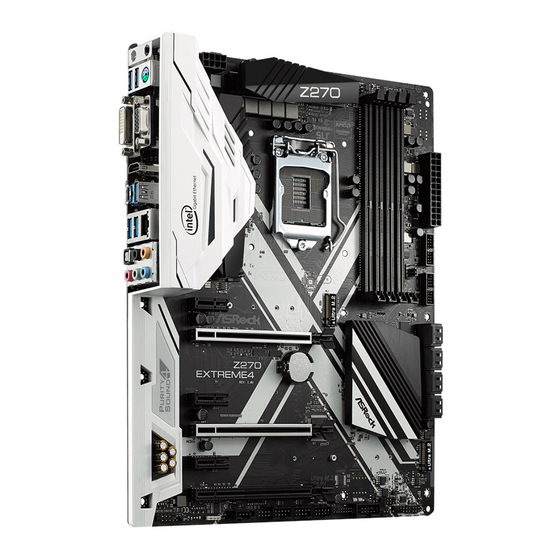
Page 14: Motherboard Layout
1.3 Motherboard Layout RoHS CPU_FAN1 ATX12V1 CPU_OPT/W_PUMP M2_3 HDMI1 USB 3.1 T: USB31_TA_1 B: USB31_TC_1 USB 3.0 Top: T: USB3 RJ-45 B: USB4 CHA_FAN2 CHA_FAN1 PCIE1 PCIE2 CMOS Z270 Intel Battery EXTREME4 Z270 Purity PCIE3 Sound 4 PCIE4 PCIE5 BIOS_A1 BIOS_B_LED1 BIOS PCIE6... - Page 15 Z270 Extreme4 No. Description ATX 12V Power Connector (ATX12V1) CPU Fan Connector (CPU_FAN1) CPU Fan / Waterpump Fan Connector (CPU_OPT/W_PUMP) 2 x 288-pin DDR4 DIMM Slots (DDR4_A1, DDR4_B1) 2 x 288-pin DDR4 DIMM Slots (DDR4_A2, DDR4_B2) ATX Power Connector (ATXPWR1) USB 3.0 Header (USB3_7_8)
-
Page 16: I/O Panel
1.4 I/O Panel No. Description No. Description PS/2 Mouse/Keyboard Port (PS2_KB1) Optical SPDIF Out Port D-Sub Port (VGA1) USB 3.0 Ports (USB3_34)*** LAN RJ-45 Port* USB 3.1 Type-A Port (USB31_TA_1) Central / Bass (Orange) USB 3.1 Type-C Port (USB31_TC_1) Rear Speaker (Black) HDMI Port (HDMI1) Line In (Light Blue) DVI-D Port (DVI1) - Page 17 Z270 Extreme4 * There are two LEDs on each LAN port. Please refer to the table below for the LAN port LED indications. ACT/LINK LED SPEED LED LAN Port Activity / Link LED Speed LED Status Description Status Description No Link...
-
Page 18: Chapter 2 Installation
Chapter 2 Installation This is an ATX form factor motherboard. Before you install the motherboard, study the configuration of your chassis to ensure that the motherboard fits into it. Pre-installation Precautions Take note of the following precautions before you install motherboard components or change any motherboard settings. -
Page 19: Installing The Cpu
Z270 Extreme4 2.1 Installing the CPU 1. Before you insert the 1151-Pin CPU into the socket, please check if the PnP cap is on the socket, if the CPU surface is unclean, or if there are any bent pins in the socket. Do not force to insert the CPU into the socket if above situation is found. - Page 21 Z270 Extreme4 Please save and replace the cover if the processor is removed. The cover must be placed if you wish to return the motherboard for after service.
-
Page 22: Installing The Cpu Fan And Heatsink
2.2 Installing the CPU Fan and Heatsink... -
Page 23: Installing Memory Modules (Dimm)
Z270 Extreme4 2.3 Installing Memory Modules (DIMM) This motherboard provides four 288-pin DDR4 (Double Data Rate 4) DIMM slots, and supports Dual Channel Memory Technology. 1. For dual channel configuration, you always need to install identical (the same brand, speed, size and chip-type) DDR4 DIMM pairs. -
Page 25: Expansion Slots (Pci Express Slots)
Z270 Extreme4 2.4 Expansion Slots (PCI Express Slots) There are 6 PCI Express slots on the motherboard. Before installing an expansion card, please make sure that the power supply is switched off or the power cord is unplugged. Please read the documentation of the expansion card and make necessary hardware settings for the card before you start the installation. -
Page 26: Jumpers Setup
2.5 Jumpers Setup The illustration shows how jumpers are setup. When the jumper cap is placed on the pins, the jumper is “Short”. If no jumper cap is placed on the pins, the jumper is “Open”. The illustration shows a 3-pin jumper whose pin1 and pin2 are “Short” when a jumper cap is placed on these 2 pins. -
Page 27: Onboard Headers And Connectors
Z270 Extreme4 2.6 Onboard Headers and Connectors Onboard headers and connectors are NOT jumpers. Do NOT place jumper caps over these headers and connectors. Placing jumper caps over the headers and connectors will cause permanent damage to the motherboard. System Panel Header... - Page 28 Power LED and Speaker Please connect the SPEAKER DUMMY Header chassis power LED and DUMMY (7-pin SPK_PLED1) the chassis speaker to this (see p.8, No. 15) header. PLED+ PLED+ PLED- Serial ATA3 Connectors These eight SATA3 (SATA3_4_5: connectors support SATA see p.8, No.
- Page 29 Z270 Extreme4 USB 3.0 Header Besides four USB 3.0 ports Vbus Vbus Vbus IntA_PB_SSRX- (19-pin USB3_5_6) on the I/O panel, there IntA_PA_SSRX- IntA_PB_SSRX+ IntA_PA_SSRX+ (see p.8, No. 9) are two headers on this IntA_PB_SSTX- IntA_PA_SSTX- IntA_PB_SSTX+ (19-pin USB3_7_8) motherboard. Each USB...
- Page 30 Chassis Optional/Water This motherboard FAN_VOLTAGE Pump Fan Connector provides two 4-Pin water FAN_SPEED (4-pin CHA_FAN3/W_ cooling chassis fan FAN_SPEED_CONTROL PUMP) connectors. If you plan to (see p.8, No. 16) connect a 3-Pin chassis water cooler fan, please connect it to Pin 1-3. CPU Fan Connector This motherboard pro- FAN_SPEED_CONTROL...
- Page 31 Z270 Extreme4 Thunderbolt AIC Please connect a Thunderbolt™ Connectors add-in card (AIC) to the (5-pin TB1) Thunderbolt AIC connector via DUMMY (see p.8, No. 23) the GPIO cable. I2C_DATA (10-pin TB2) *Please install the Thunderbolt™ I2C_CLOCK (see p.8, No. 22) AIC card to PCIE6 (default slot).
-
Page 32: Sli Tm And Quad Sli
2.7 SLI and Quad SLI Operation Guide ® This motherboard supports NVIDIA and Quad SLI (Scalable Link Interface) technology that allows you to install up to two identical PCI Express x16 graphics cards. Requirements ® 1. You should only use identical SLI -ready graphics cards that are NVIDIA certified. - Page 33 Z270 Extreme4 Step 3 Align and insert the ASRock SLI_HB_ Bridge_2S Card to the goldfingers on each graphics card. Make sure the ASRock SLI_ HB_Bridge_2S Card is firmly in place. SLI_HB_Bridge_2S Car d ASRock SLI_HB_Bridge_2S Card Step 4 Connect a VGA cable or a DVI cable to the...
-
Page 34: Driver Installation And Setup
2.7.2 Driver Installation and Setup Install the graphics card drivers to your system. After that, you can enable the ® Multi-Graphics Processing Unit (GPU) in the NVIDIA nView system tray utility. Please follow the below procedures to enable the multi-GPU. For SLI and Quad SLI mode... -
Page 35: Tm And Quad Crossfirex
Z270 Extreme4 2.8 CrossFireX , 3-Way CrossFireX and Quad CrossFireX Operation Guide This motherboard supports CrossFireX , 3-way CrossFireX and Quad CrossFireX that allows you to install up to three identical PCI Express x16 graphics cards. 1. You should only use identical CrossFireX -ready graphics cards that are AMD certified. - Page 36 Step 3 Connect a VGA cable or a DVI cable to the monitor connector or the DVI connec- tor of the graphics card that is inserted to PCIE2 slot.
-
Page 37: Installing Three Crossfirex
Z270 Extreme4 2.8.2 Installing Three CrossFireX -Ready Graphics Cards Step 1 Insert one graphics card into PCIE2 slot, another graphics card to PCIE4 slot, and the other graphics card to PCIE6 slot. Make sure that the cards are properly seated on the slots. -
Page 38: Driver Installation And Setup
2.8.3 Driver Installation and Setup Step 1 Power on your computer and boot into OS. Step 2 Remove the AMD drivers if you have any VGA drivers installed in your system. The Catalyst Uninstaller is an optional download. We recommend using this utility to un- install any previously installed Catalyst drivers prior to installation. -
Page 39: Wifi/Bt Module Installation Guide
Z270 Extreme4 2.9 M.2 WiFi/BT Module Installation Guide The M.2 Socket (Key E) supports type 2230 WiFi/BT module. Installing the WiFi/BT module Step 1 Prepare a type 2230 WiFi/BT module and the screw. Step 2 Find the nut location to be used. - Page 40 Step 4 Tighten the screw with a screwdriver to secure the module into place. Please do not overtighten the screw as this might damage the module.
-
Page 41: M.2_Ssd (Ngff) Module Installation Guide
Z270 Extreme4 2.10 M.2_SSD (NGFF) Module Installation Guide The M.2, also known as the Next Generation Form Factor (NGFF), is a small size and versatile card edge connector that aims to replace mPCIe and mSATA. The Ultra M.2 Socket (M2_1 and M2_2) supports SATA3 6.0 Gb/s module and M.2 PCI Express module up to Gen3 x4 (32 Gb/s). - Page 42 Step 3 Move the standoff based on the module type and length. The standoff is placed at the nut location D by default. Skip Step 3 and 4 and go straight to Step 5 if you are going to use the default nut. Otherwise, release the standoff by hand.
- Page 43 Z270 Extreme4 Step 6 Tighten the screw with a screwdriver to secure the module into place. Please do not overtighten the screw NUT2 NUT1 as this might damage the module. M.2_SSD (NGFF) Module Support List Vendor Size Interface Length ADATA...
- Page 44 Vendor Size Interface Length V-Color 240GB SATA3 2280 VLM100-240G-2280B-RD V-Color 240GB SATA3 2280 VSM100-240G-2280 For the latest updates of M.2_SSD (NFGG) module support list, please visit our website for details: http://www.asrock.com...
-
Page 45: Chapter 3 Software And Utilities Operation
Z270 Extreme4 Chapter 3 Software and Utilities Operation 3.1 Installing Drivers The Support CD that comes with the motherboard contains necessary drivers and useful utilities that enhance the motherboard’s features. Running The Support CD To begin using the support CD, insert the CD into your CD-ROM drive. The CD automatically displays the Main Menu if “AUTORUN”... -
Page 46: A-Tuning
3.2 A-Tuning A-Tuning is ASRock’s multi purpose software suite with a new interface, more new features and improved utilities. 3.2.1 Installing A-Tuning A-Tuning can be downloaded from ASRock Live Update & APP Shop. After the installation, you will find the icon “A-Tuning“ on your desktop. Double-click the “A-Tuning“... - Page 47 Z270 Extreme4 OC Tweaker Configurations for overclocking the system. System Info View information about the system. *The System Browser tab may not appear for certain models.
- Page 48 Configure up to five different fan speeds using the graph. The fans will automatically shift to the next speed level when the assigned temperature is met. Settings Configure ASRock A-Tuning. Click to select "Auto run at Windows Startup" if you want A-Tuning to be launched when you start up the Windows operating system.
-
Page 49: Asrock Live Update & App Shop
Double-click on your desktop to access ASRock Live Update & APP Shop utility. *You need to be connected to the Internet to download apps from the ASRock Live Update & APP Shop. 3.3.1 UI Overview Category Panel Hot News... -
Page 50: Apps
3.3.2 Apps When the "Apps" tab is selected, you will see all the available apps on screen for you to download. Installing an App Step 1 Find the app you want to install. The most recommended app appears on the left side of the screen. The other various apps are shown on the right. - Page 51 Z270 Extreme4 Step 3 If you want to install the app, click on the red icon to start downloading. Step 4 When installation completes, you can find the green "Installed" icon appears on the upper right corner. To uninstall it, simply click on the trash can icon...
- Page 52 Upgrading an App You can only upgrade the apps you have already installed. When there is an available new version for your app, you will find the mark of "New Version" appears below the installed app icon. Step 1 Click on the app icon to see more details. Step 2 Click on the yellow icon to start upgrading.
-
Page 53: Bios & Drivers
Z270 Extreme4 3.3.3 BIOS & Drivers Installing BIOS or Drivers When the "BIOS & Drivers" tab is selected, you will see a list of recommended or critical updates for the BIOS or drivers. Please update them all soon. Step 1 Please check the item information before update. -
Page 54: Setting
3.3.4 Setting In the "Setting" page, you can change the language, select the server location, and determine if you want to automatically run the ASRock Live Update & APP Shop on Windows startup. -
Page 55: Enabling Usb Ports For Windows® 7 Installation
Requirements A Windows® 7 installation disk or USB drive • A Windows® PC • Win7 USB Patcher (included in the ASRock Support CD or downloaded from • website) Scenarios You have an ODD and PS/2 ports: If there is an optical disc drive, PS/2 ports and PS/2 Keyboard or mouse on your computer, you can skip the instructions below and go ahead to install Windows®... - Page 56 Instructions Step 1 Insert the Windows® 7 installation disk or USB drive to your system. Step 2 Extract the tool (Win7 USB Patcher) and launch it. Step 3 Select how you want to install Windows 7 later. Step 4 Locate your Win7 source folder or your ISO file.
- Page 57 Z270 Extreme4 Step 5 Select the USB storage, compact disk or destination folder for the new Windows 7 installation file. Step 6 Click “Start” to begin. Step 7 Now you are able to install Windows® 7 on Intel® new processors with the new burned CD.
-
Page 58: Asrock Aura Rgb Led
3.5 ASRock AURA RGB LED ASRock AURA RGB LED allows you to build your own colorful lighting system. By connecting LED strip, you can adjust the RGB LED color through ASRock AURA RGB LED utility. Drag the tab to customize your preference. -
Page 59: Chapter 4 Uefi Setup Utility
Z270 Extreme4 Chapter 4 UEFI SETUP UTILITY 4.1 Introduction This section explains how to use the UEFI SETUP UTILITY to configure your system. You may run the UEFI SETUP UTILITY by pressing <F2> or <Del> right after you power on the computer, otherwise, the Power-On-Self-Test (POST) will continue with its test routines. -
Page 60: Ez Mode
4.2 EZ Mode The EZ Mode screen appears when you enter the BIOS setup program by default. EZ mode is a dashboard which contains multiple readings of the system’s current status. You can check the most crucial information of your system, such as CPU speed, DRAM frequency, SATA information, fan speed, etc. -
Page 61: Advanced Mode
Z270 Extreme4 4.3 Advanced Mode The Advanced Mode provides more options to configure the BIOS settings. Refer to the following sections for the detailed configurations. To access the EZ Mode, press <F6> or click the "EZ Mode" button at the upper right corner of the screen. -
Page 62: Navigation Keys
4.3.2 Navigation Keys Use < > key or < > key to choose among the selections on the menu bar, and use < > key or < > key to move the cursor up or down to select items, then press <Enter>... -
Page 63: Main Screen
Z270 Extreme4 4.4 Main Screen When you enter the UEFI SETUP UTILITY, the Main screen will appear and display the system overview. Favorite Display your collection of BIOS items. Press F5 to add/remove your favorite items. -
Page 64: Oc Tweaker Screen
4.5 OC Tweaker Screen In the OC Tweaker screen, you can set up overclocking features. Because the UEFI software is constantly being updated, the following UEFI setup screens and descriptions are for reference purpose only, and they may not exactly match what you see on your screen. -
Page 65: Cpu Configuration
Z270 Extreme4 CPU Configuration Multi Core Enhancement Improve the system's performance by forcing the CPU to perform the highest frequency on all CPU cores simultaneously. Disable to reduce power consumption . CPU Ratio The CPU speed is determined by the CPU Ratio multiplied with the BCLK. -
Page 66: Long Duration Maintained
cies and voltage points for better power saving and heat dissipation. Intel Turbo Boost Technology Intel Turbo Boost Technology enables the processor to run above its base operating frequency when the operating system requests the highest performance state. Intel Speed Shift Technology Enable/Disable Intel Speed Shift Technology support. -
Page 67: Dram Timing Configuration
Z270 Extreme4 DRAM Timing Configuration BCLK Frequency The CPU speed is determined by the CPU Ratio multiplied with the BCLK. Increasing the BCLK will increase the internal CPU clock speed but also affect the clock speed of other components. DRAM Frequency If [Auto] is selected, the motherboard will detect the memory module(s) inserted and assign the appropriate frequency automatically. - Page 68 RAS to RAS Delay (tRRD_L) The number of clocks between two rows activated in different banks of the same rank. RAS to RAS Delay (tRRD_S) The number of clocks between two rows activated in different banks of the same rank. Write to Read Delay (tWTR_L) The number of clocks between the last valid write operation and the next read command to the same internal bank.
- Page 69 Z270 Extreme4 tRDRD_dr Configure between module read to read delay. tRDRD_dd Configure between module read to read delay. tRDWR_sg Configure between module read to write delay. tRDWR_dg Configure between module read to write delay. tRDWR_dr Configure between module read to write delay.
-
Page 70: Advanced Setting
Advanced Setting MRC Fast Boot Enable Memory Fast Boot to skip DRAM memory training for booting faster. Voltage Configuration CPU Vcore Voltage Configure the voltage for the CPU Vcore. CPU Load-Line Calibration CPU Load-Line Calibration helps prevent CPU voltage droop when the system is under heavy loading. -
Page 71: Advanced Screen
Z270 Extreme4 4.6 Advanced Screen In this section, you may set the configurations for the following items: CPU Configuration, Chipset Configuration, Storage Configuration, Intel® Thunderbolt, Super IO Configuration, ACPI Configuration, USB Configuration and Trusted Computing. Setting wrong values in this section may cause the system to malfunction. -
Page 72: Cpu Configuration
4.6.1 CPU Configuration Intel Hyper Threading Technology Intel Hyper Threading Technology allows multiple threads to run on each core, so that the overall performance on threaded software is improved. Active Processor Cores Select the number of cores to enable in each processor package. CPU C States Support Enable CPU C States Support for power saving. -
Page 73: Intel Virtualization Technology
Z270 Extreme4 Package C State Support Enable CPU, PCIe, Memory, Graphics C State Support for power saving. CFG Lock This item allows you to disable or enable the CFG Lock. CPU Thermal Throttling Enable CPU internal thermal control mechanisms to keep the CPU from overheat- ing. -
Page 74: Chipset Configuration
4.6.2 Chipset Configuration Primary Graphics Adapter Select a primary VGA. Top Of Lower Usable Dram Maximum Value of TOLUD. Dynamic assignment would adjust TOLUD automatically based on largest MMIO length of installed graphic controller. VT-d Intel® Virtualization Technology for Directed I/O helps your virtual machine monitor better utilize hardware by improving application compatibility and reliability, and providing additional levels of manageability, security, isolation, and I/O performance. - Page 75 Z270 Extreme4 PCIE4 Link Speed Select the link speed for PCIE4. PCIE5 Link Speed Select the link speed for PCIE5. PCIE6 Link Speed Select the link speed for PCIE6. PCI Express Native Control Select Enable for enhanced PCI Express power saving in OS.
-
Page 76: Front Panel
Onboard HD Audio Enable/disable onboard HD audio. Set to Auto to enable onboard HD audio and automatically disable it when a sound card is installed. Front Panel Enable/disable front panel HD audio. Onboard HDMI HD Audio Enable audio for the onboard digital outputs. WAN Radio Enable/disable the WiFi module's connectivity. -
Page 77: Storage Configuration
Z270 Extreme4 4.6.3 Storage Configuration SATA Controller(s) Enable/disable the SATA controllers. SATA Controller Speed Indicates the maximum speed the SATA controller can support. SATA Mode Selection AHCI: Supports new features that improve performance. RAID: Combine multiple disk drives into a logical unit. - Page 78 ASMedia SATA3 Mode IDE: For better compatibility. AHCI: Supports new features that improve performance. M2_1/ SATA3_0_1 Switch Auto: M2_1/SATA3_0_1 auto switch Force_SATA: Switch to SATA3_0_1 Force_M2_1: Switch to M2_1 M2_2/ SATA3_4_5 Switch Auto: M2_2/SATA3_4_5 auto switch Force_SATA: Switch to SATA3_4_5 Force_M2_2: Switch to M2_2...
-
Page 79: Intel® Thunderbolt
Z270 Extreme4 4.6.4 Intel® Thunderbolt™ Intel(R) Thunderbolt Technology Enable/Disable the Intel(R) Thunderbolt function. Security Level Allows you to choose a security level for the Thunderbolt ports... -
Page 80: Super Io Configuration
4.6.5 Super IO Configuration Serial Port Enable or disable the Serial port. Serial Port Address Select the address of the Serial port. PS2 Y-Cable Enable the PS2 Y-Cable or set this option to Auto. -
Page 81: Acpi Configuration
Z270 Extreme4 4.6.6 ACPI Configuration Suspend to RAM Select disable for ACPI suspend type S1. It is recommended to select auto for ACPI S3 power saving. ACPI HEPT Table Enable the High Precision Event Timer for better performance. PS/2 Keyboard Power On Allow the system to be waked up by a PS/2 Keyboard. - Page 82 USB Keyboard/Remote Power On Allow the system to be waked up by an USB keyboard or remote controller. USB Mouse Power On Allow the system to be waked up by an USB mouse.
-
Page 83: Usb Configuration
Z270 Extreme4 4.6.7 USB Configuration Legacy USB Support Enable or disable Legacy OS Support for USB 2.0 devices. If you encounter USB compatibility issues it is recommended to disable legacy USB support. Select UEFI Setup Only to support USB devices under the UEFI setup and Windows/Linux operating systems only. -
Page 84: Trusted Computing
4.6.8 Trusted Computing Security Device Support Enable or disable BIOS support for security device. -
Page 85: Tools
ASRock System Browser shows the overview of your current PC and the devices connected. UEFI Tech Service Contact ASRock Tech Service if you are having trouble with your PC. Please setup network configuration before using UEFI Tech Service. Easy RAID Installer Easy RAID Installer helps you to copy the RAID driver from the support CD to your USB storage device. - Page 86 Save UEFI files in your USB storage device and run Instant Flash to update your UEFI. Internet Flash - DHCP (Auto IP), Auto ASRock Internet Flash downloads and updates the latest UEFI firmware version from our servers for you. Please setup network configuration before using Internet Flash.
-
Page 87: Network Configuration
Z270 Extreme4 Network Configuration Use this to configure internet connection settings for Internet Flash. Internet Setting Enable or disable sound effects in the setup utility. UEFI Download Server Select a server to download the UEFI firmware. -
Page 88: Hardware Health Event Monitoring Screen
4.8 Hardware Health Event Monitoring Screen This section allows you to monitor the status of the hardware on your system, including the parameters of the CPU temperature, motherboard temperature, fan speed and voltage. Fan Tuning Measure Fan Min Duty Cycle. Fan-Tastic Tuning Select a fan mode for CPU Fans 1&2, or choose Customize to set 5 CPU temperatures and assign a respective fan speed for each temperature. - Page 89 Z270 Extreme4 CPU_OPT / W _ Pump Switch Select CPU Optional or Water Pump mode. CPU Optional Fan Control Mode Select PWM mode or DC mode for CPU Optional fan. CPU Optional Fan Setting Select a fan mode for CPU Optional fan, or choose Customize to set 5 CPU temperatures and assign a respective fan speed for each temperature.
- Page 90 Chassis Fan 2 Step Up Set the value of Chassis Fan 2 Step Up. Chassis Fan 2 Step Down Set the value of Chassis Fan 2 Step Down. CHA_FAN3 / W _ Pump Switch Select CHA_FAN3/CPU Optional or Water Pump mode. Chassis Fan 3 Control Mode Select PWM mode or DC mode for Chassis Fan 3.
-
Page 91: Security Screen
Z270 Extreme4 4.9 Security Screen In this section you may set or change the supervisor/user password for the system. You may also clear the user password. Supervisor Password Set or change the password for the administrator account. Only the administrator has authority to change the settings in the UEFI Setup Utility. -
Page 92: Boot Screen
4.10 Boot Screen This section displays the available devices on your system for you to configure the boot settings and the boot priority. Boot From Onboard LAN Allow the system to be waked up by the onboard LAN. Setup Prompt Timeout Configure the number of seconds to wait for the setup hot key. -
Page 93: Launch Storage Oprom Policy
Z270 Extreme4 Boot Failure Guard Message If the computer fails to boot for a number of times the system automatically restores the default settings. CSM (Compatibility Support Module) Enable to launch the Compatibility Support Module. Please do not disable unless you’re running a WHCK test. -
Page 94: Exit Screen
4.11 Exit Screen Save Changes and Exit When you select this option the following message, “Save configuration changes and exit setup?” will pop out. Select [OK] to save changes and exit the UEFI SETUP UTILITY. Discard Changes and Exit When you select this option the following message, “Discard changes and exit setup?”... -
Page 95: Contact Information
Contact Information If you need to contact ASRock or want to know more about ASRock, you’re welcome to visit ASRock’s website at http://www.asrock.com; or you may contact your dealer for further information. For technical questions, please submit a support request form at http://www.asrock.com/support/tsd.asp...
Need help?
Do you have a question about the Z270 Extreme4 and is the answer not in the manual?
Questions and answers