
Related Manuals for Moore 535 PROFILER

Summary of Contents for Moore 535 PROFILER
- Page 1 5 3 5 P R O F I L E R 1/4 DIN PROFILE CONTROLLER USER'S MANUAL M535-PROF V 6 , © JULY 20 17...
- Page 2 Isolation Block Diagram A-23 535-PROF User's Manual Appendix 7...
-
Page 3: Table Of Contents
Table of Contents TABLE OF CONTENTS CHAPTER 1 About This Manual: INTRODUCTION ................1 Throughout this User’s Manual 535 Profile Controller Modes .............. 1 information appears along the Order Code, Packaging Information ........... 2 margins (NOTE: CAUTION! and Where to Go Next................2 WARNING!). - Page 4 Table of Contents CHAPTER 3 PAGE INSTALLATION (CONTINUED) Output Modules 3. DC Logic (SSR Drive) Output .......... 18 4. Milliamp Output .............. 18 5. Position Proportioning Output ......... 18 Serial Communications ............19 Limit Control ................20 CHAPTER 4 HARDWARE SET UP ..............21 Hardware Input Types ..............
- Page 5 Table of Contents CHAPTER 7 PAGE APPLICATIONS (CONTINUED) A. Profile Control Master/Slave Operation ............84 Hardware Configuration ............85 B. Control Type ................85 Software Configuration ............85 C. Alarms ..................86 Software Configuration ............86 D. Duplex Control ................90 Hardware Configuration ............
- Page 6 Table of Contents CHAPTER 7 PAGE APPLICATIONS (CONTINUED) N. Self Tune—Powertune® Software Configurations ............104 Pretune by Itself..............104 Pretune Type 1 & Adaptive Tune ........104 Pretune Type 2 or 3 & Adaptive Tune ........ 106 Adaptive Tune by Itself ............. 106 Self Tuning with Multiple Sets of PID .........
- Page 7 Table of Contents APPENDIX 1 PAGE MENU FLOWCHARTS ..............A-1 APPENDIX 2 PARTS LIST .................. A-3 APPENDIX 3 TROUBLESHOOTING ..............A-4 APPENDIX 4 CALIBRATION ................A-6 Preparation For All Input Calibrations ..........A-7 Thermocouple Cold Junction Calibration ......... A-8 Analog Milliamp Input Calibration ............ A-8 Milliamp Output Calibration .............
- Page 8 Table of Contents LIST OF FIGURES Figure 2.1 ..Operator Interface ..............4 Figure 2.2 ..Before and After Acknowledging An Alarm ......9 Figure 3.1 ..Instrument Panel & Cutout Dimensions ....... 11 Figure 3.2 ..Attaching Mounting Collar........... 11 Figure 3.3 ..
-
Page 9: Figure 3.5
Table of Contents Figure 7.10..Duplex with Two On/Off Outputs ......... 94 Figure 7.11..Staged Outputs Example ........... 97 Figure 7.12..Combinations of Closed Digital Inputs for Each Setpoint (Based on BCD Logic) ........98 Figure 7.13..Pretune Type 1, Type 2 and Type 3 with Adaptive Tune .............. -
Page 10: Chapter 1 Introduction
Introduction CHAPTER 1 INTRODUCTION Thank you for selecting the 535 Profile From its surge-resistant power supply to its rugged construction, the 535 Profile Controller — the most sophisticated Controller is designed to ensure the integrity of your process with maximum reli- instrument in its class. -
Page 11: Order Code, Packaging Information
Introduction SET UP, also referred to as configuration. Here the basic functions of the instru- ment are configured, such as input and output assignments, alarm types and special functions. TUNING, where control function parameters for Proportional, Integral and Deri- vation (PID) are configured. Use this mode periodically to optimize the control performance of the instrument. - Page 12 Introduction 535 – Order Output 1: Control Code None Mechanical Relay (5 amp) Analog (milliamp) Solid State Relay (triac) (1 amp) DC Logic (SSR drive) Output 2: Control, Alarm, or Retransmission None Mechanical Relay (5 amp) Analog (milliamp) Solid State Relay (triac) (1 amp) DC Logic (SSR drive) Output 3: Control, Alarm, Retransmission, or Loop Power None...
-
Page 13: Chapter 2 Basic Interface
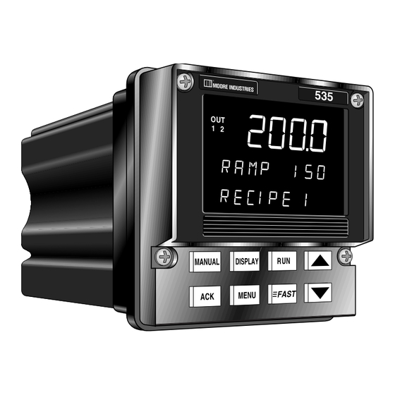
Operation CHAPTER 2 BASIC INTERFACE Displays: Icons Figure 2.1 Operator Interface Location for identification MANUAL DISPLAY label MENU FAST Keys DISPLAYS The display strategy of the 535 Profile Controller is the same for all modes. 1st Display (five 7-segment digits) •... -
Page 14: Icons (Lit)
Operation b. The amount of time left in the current ramp or soak segment or the amount of time the soak segment has been waiting to run or continue due to guaranteed soak, for example: 15:03 LEFT means “15:03 is remaining in this segment’s current cycle” WAIT 12:37 means “the soak segment has been waiting for 12:37”... - Page 15 Operation DISPLAY DISPLAY Press to toggle through values in the 2nd display for setpoint, ramping setpoint (if available), deviation, PV1 (If PV source is not PV1), PV2 (if PV Source is not PV1), output and valve position (if available). In RECIPE SET UP, TUNING, SET UP mode, press to return controller to OPERATION mode (display will show current setpoint).
-
Page 16: Basic Profile Controller Operating Procedures
Operation BASIC PROFILE CONTROLLER OPERATING PROCEDURES Use the following as a quick guide to key operating functions of the 535-PROF. To Enter the RECIPE SET UP Mode 1. To enter the RECIPE SET UP mode from any other mode, hold down FAST and press MENU. -
Page 17: To Display The Setpoint (Sp) While A Recipe Is Running
Operation will control to the IDLE setpoint. The raise and lower keys may be used to adjust the setpoint. To display the setpoint (SP), ramping setpoint (RAMP), deviation (DEV) or output % (OUT %) while a recipe is run- ning: 1. -
Page 18: To Display Control Output Value
Operation 2. If the code is correct, CORRECT appears in the 3rd display. The display will clear after two seconds, allowing full access. 4. If code is incorrect, INCORRECT appears in the 3rd display. This will dis- appear after two seconds, and a new security code can then be entered. 5. -
Page 19: To Acknowledge An Alarm(S)
Operation NOTE: To acknowledge an alarm(s): All alarms are software alarms unless 1. To acknowledge Alarm 1, press ACK once. tied to an output relay in the SET UP mode. See Chapters 5 and 7 for 2. To acknowledge Alarm 2, press ACK twice. details on alarms. -
Page 20: Installation
Install / Wire CHAPTER 3 INSTALLATION MOUNTING THE CONTROLLER The 535-PROF front face is NEMA 4X rated (waterproof). To obtain a waterproof seal between the controller and the panel, follow these directions: 1. The 535-PROF fits in a standard 1/4 DIN cutout. Mount the 535-PROF in any panel with a thickness from .06 in. -
Page 21: Wiring
Install / Wire tighten the screws (using a Phillips #2 screwdriver) to secure the controller CAUTION! against the panel. The enclosure into which the 535- PROF Controller is mounted must be 7. If there is difficulty with any of the mounting requirements, apply a bead of grounded. -
Page 22: Ac Power Input
Install / Wire AC Power Input Terminals 1 and 2 are for power. Terminal 9 is the earth ground. Use a 0.5 Amp, 250 V, fast-acting fuse in line with your AC power connection. EARTH/ GROUND POWER Figure 3.4 AC Power Input Terminals CAUTION! Do not run low power (sensor input) lines in the same bundle as AC power... -
Page 23: Figure 3.6
Install / Wire For PV2 NOTE: For PV1 Typically, in the U.S., negative leads are red. THERMOCOUPLE INPUT THERMOCOUPLE INPUT Figure 3.6 PV1 and PV2 Wiring for Milliamp, RTD and Voltage Inputs. Chapter 3 535-PROF User's Manual... -
Page 24: Figure 3.7 ....... Pv1 And Pv2 Wiring For Milliamp Inputs With Internal And External Power Supply
Install / Wire For PV2 For PV1 Figure 3.7 MILLIAMP INPUT PV1 and PV2 Wiring for Milliamp MILLIAMP INPUT Inputs with Internal and External 2-wire transmitter with 2-wire transmitter with Power Supply separate power supply separate power supply – External External Power Supply Power Supply... -
Page 25: Digital Input(S)
Install / Wire Digital Input(s) Digital inputs can be activated in three ways: a switch (signal type), closure of a relay, or an open collector transistor. Digital inputs are only functional when that option is installed (via hardware) The controller detects the hardware and supplies the appropriate software menu. -
Page 26: Output Modules
Install / Wire OUTPUT MODULES The 535-PROF output modules are used for control, alarms and retransmission. The four output module types are: Mechanical Relay, Solid State Relay (Triac), DC Logic (SSR Drive) and Analog (Milliamp) To install these modules, plug them into any of the four output sockets on the printed circuit boards (refer to Chapter 4). -
Page 27: Dc Logic (Ssr Drive) Output
Install / Wire 3. DC Logic (SSR Drive) Output • Output 1 is always Control 1. • Respective jumper J1, J2 or J3 must be set to normally open for DC Logic output. • Output 4 is always configured for normally open. Terminals used Terminals used Terminals used... -
Page 28: Serial Communications
Install / Wire • Mechanical relay or solid state relay modules must be installed in output sockets 1 and 2. • When using velocity control (no slidewire feedback), there are no con- nections at terminals 10, 11 and 12. • Use of the slidewire feedback is optional Serial Communications A twisted shielded pair of wires should be used to interconnect the host and... -
Page 29: Limit Control
Install / Wire Limit Control Temperature applications where abnormally high or low temperature conditions pose potential hazards for damage to equipment, product and operator. For such applications, we recommend the use of an FM-approved temperature limit device in conjunction with the process controller. This wiring example illustrates a typical application using the 535-PROF Process Controller with a 353 Limit Figure 3.17 Controller. -
Page 30: Chapter 4 Hardware Set Up
Hardware Set Up CHAPTER 4 HARDWARE SET UP Hardware configuration determines the available outputs as well as the type of input signal. The 535-PROF controller comes factory set with the following: • All specified module and options installed (for details, refer to the Order Code in Chapter 1). -
Page 31: The Remote Setpoint
Hardware Set Up NOTE: The Remote Setpoint Changing the jumpers means moving Figure 4.2 shows the location of the remote setpoint jumper. The factory de- the jumper connector. The jumper fault is milliamp. Choose from the following settings: connector slips over the pins, straddling two rows of pins. -
Page 32: Accessing And Changing Jumpers
Hardware Set Up CAUTION!! ACCESSING AND CHANGING JUMPERS Static discharge can cause damage to equipment. Always use a wrist Follow these instruction to change jumpers for the Process Variable, Remote grounding strap when handling Setpoint and Digital Inputs: electronics to prevent static discharge. Equipment needed: Needle-nose pliers (optional) Phillips screwdriver (#2) -
Page 33: Adding And Changing Output Modules
Hardware Set Up ADDING AND CHANGING OUTPUT MODULES The 535-PROF has provisions for four output modules. A controller ordered with output module options already has the modules properly installed. Follow these instruction to add modules, change module type(s) or change module location(s). Equipment needed: Wrist grounding strap Phillips screwdriver (#2) -
Page 34: Appendix
Hardware Set Up 6. To change module 4: Output Module 4 (on the Option board) is also held in place by a tie wrap. Snip tie wrap to remove module as shown in Photo 6 . 7. Figure 4.3 shows a representation of an output module. Inspect the module(s) to make sure that the pins are straight. -
Page 35: Special Communications Module
Hardware Set Up SPECIAL COMMUNICATIONS MODULE A special communications module is available for the 535-PROF; see order code in Chapter 1 for details. Equipment needed: Wrist grounding strap Phillips screwdriver (#2) Small flat blade screwdriver 1. Before installing the communications module, set up the hardware wiring for the application. -
Page 36: Software Configuration
Controller Set Up CHAPTER 5 SOFTWARE CONFIGURATION The software configuration menus of the 535-PROF contain user-selected vari- ables that define the action of the controller. Read through this section before Figure 5.1 making any parameter adjustments to the controller. Menu Flowchart for Set Up When initially setting up the This is a Menu. - Page 37 Controller Set Up MANUAL to place controller under Manual Control MENU MANUAL Figure 5.2 TUNING Configuration Flowchart OPERATION DISPLAY FAST + MENU to scroll RECIPE # DISPLAY thru recipes FAST + MENU Set Up Mode DISPLAY is only accessible if SET UP controller is under to return to...
-
Page 38: Parameters
Controller Set Up PARAMETERS TUNE PT. CONTACT 1 Within each menu are parameters for particular control functions. Select val- AUTOMATIC MANUAL ues for each parameter depending on the specific application. Use the MENU key to access parameters for a particular menu; the parameter name will re- place the menu name in the 2nd display, and the parameter value will show in Figure 5.3 the 3rd display. - Page 39 Controller Set Up • For information about applications for the 535-PROF, see Chapter 7. • For more information about the Tuning function of the 535-PROF, see Chap- ter 6. Access Set Up Return to Operation Next menu Next parameter Next value Access Tuning Return to Operation ▲...
-
Page 40: Software Menus And Parameters
Controller Set Up SOFTWARE MENUS AND PARAMETERS CONFIG. CONFIG. 1. CTRL. TYPE Defines the type of control output(s). CTRL. TYPE D STANDARD Standard control output, no special algorithms • POS. PROP. Position proportioning control output STANDARD • STAGED Staged outputs •... -
Page 41: Figure 3.4
Controller Set Up 6. OUTPUT 3 OUTPUT 3 Defines the function of the third output. • ALM/EV:ON For an alarm or event output • ALM/EV:OFF For an alarm or event output • RETRANS. Retransmission • COMM. ONLY Output addressable only through communications D OFF Completely deactivates the output... - Page 42 Controller Set Up 12. CONTACT 1 Defines the operation of the first digital input. • RECIPE. 1–7 Chooses the recipe number (uses Binary contact CONTACT 1 1-3) MANUAL • SETPT. 1–8 Chooses Local setpoint 1–8 (uses BCD contacts 1–4) • REM.
- Page 43 Controller Set Up 13. CONTACT 2 CONTACT 2 Defines the operation of the second digital input. REM. SETPT. D REM. SETPT. • MANUAL • 2ND. SETPT. • 2ND. PID • ALARM ACK. • RST. INHBT. • D.A./R.A. • STOP A/T •...
- Page 44 Controller Set Up 14. CONTACT 3 CONTACT 3 Defines the operation of the third digital input. 2ND. SETPT. • REM. SETPT. • MANUAL D 2ND. SETPT. • 2ND. PID • ALARM ACK. • RST. INHBT. • D.A./R.A. • STOP A/T •...
- Page 45 Controller Set Up 15. CONTACT 4 CONTACT 4 Defines the operation of the fourth digital input. 2ND. PID • REM. SETPT. • MANUAL • 2ND. SETPT. D 2ND. PID • ALARM ACK. • RST. INHBT. • D.A./R.A. • STOP A/T •...
-
Page 46: Rec. Conf
Controller Set Up 16. CONTACT 5 CONTACT 5 This defines the operation of the fifth digital input. ALARM ACK. • REM. SETPT. • MANUAL • 2ND. SETPT. • 2ND. PID D ALARM ACK. • RST. INHBT. • D.A./R.A. • STOP A/T •... - Page 47 Controller Set Up 3. RAMP UNIT RAMP UNIT Defines ramp segment terms. TIME D TIME • RATE 4. SP START SP START Defines initial value for the first ramp segment’s setpoint. • IDLE SP the IDLE SP is the first value D PV The starting value will be adjusted to account for the initialPV value...
-
Page 48: Pv1 Input
Controller Set Up 9. HOLD EVT. HOLD EVT. Selects whether or not the last segment’s event(s) will be held active after the recipe has been successfully completed. DISABLED D DISABLED • ENABLED PV1 INPUT PV1 INPUT 1. PV1 TYPE PV1 TYPE Specifies the particular sensor range or input range for PV1. - Page 49 Controller Set Up 5. LOW RANGE LOW RANGE Specifies the engineering unit value corresponding to the lowest PV1 input value, e.g. 4 mA. R –9999 to 99999 Max. is HI RANGE D Dependent on the input selection 6. HI RANGE HI RANGE Specifies the engineering unit value corresponding to the highest PV1 input value, e.g., 20mA.
-
Page 50: Pv2 Input
Controller Set Up 12. GAIN GAIN Defines the gain to PV1. 1.000 R 0.100 to 10.000 D 1.000 13. RESTORE RESTORE Defines the control mode when a broken PV1 signal is restored. D LAST MODE LAST MODE • MANUAL • AUTOMATIC •... - Page 51 Controller Set Up 4. LINEARIZE LINEARIZE Specifies if the PV2 input is to be linearized. Thermocouples and RTD’s are automatically linearized. NONE D NONE • SQR. ROOT Square root linearization is activated. 5. LOW RANGE LOW RANGE Specifies the engineering unit value corresponding to the lowest PV2 input value, e.g.
-
Page 52: Cust. Linr
Controller Set Up CUST. LINR. CUST. LINR. Defines a custom linearization curve for PV1, if selected. Points 1 and 15 are fixed to the low and high end of the input range and require only setting a corresponding PV value. Points 2 through 14 (the Xth points) require setting both the input and PV values. -
Page 53: Control
Controller Set Up CONTROL CONTROL For configuring the choices for the control algorithm. 1. ALGORITHM ALGORITHM Defines the type of control algorithm. D PID • • • • ON/OFF • PID:ON/OFF For Duplex applications using PID for the first output and on/off for the second output 2. - Page 54 Controller Set Up D DIRECT • REVERSE 8. P.P. TYPE Defines the type of position proportioning algorithm. Choose values based on the process. P.P. TYPE Feedback option installed Feedback option not installed D SLIDEWIRE • SLIDEWIRE • VELOCITY D VELOCITY 9.
-
Page 55: Alarms
Controller Set Up 16. OUT2 STRT. OUT2 STRT. Defines the starting point for control output 2 when staging outputs. R 0 to 99% D 50% ALARMS ALARMS 1. ALM. TYPE:1 Defines the type of alarm for alarm 1. ALM. TYPE:1 •... - Page 56 Controller Set Up 4A. HIGH SP:1 HIGH SP:1 Specifies the high alarm set point for alarm 1 of type HIGH/LOW. If ALM.SRC.:1 = OUTPUT If ALM.SRC.:1 = any other type 0.0% R 0.0% to 100.0% R LOW RANGE to HI RANGE D 0.0% 4B.
- Page 57 Controller Set Up 10. MESSAGE:1 MESSAGE:1 A 9-character message associated with alarm 1. To enter message: The first character of third display will be flashing. Press the keys to scroll ALARM 1 through the character set. Press FAST key to advance to subsequent characters.
- Page 58 Controller Set Up 14A. HIGH SP:2 HIGH SP:2 Specifies the high alarm set point for alarm 2 of type HIGH/LOW. 0.0% If ALM.SRC.:2 = OUTPUT If ALM.SRC.:2 = any other type R 0.0% to 100.0% R LOW RANGE to HI RANGE D 0.0% 14B.
-
Page 59: Rem. Setpt
Controller Set Up 20. MESSAGE:2 MESSAGE:2 A 9-character message associated with alarm 2. To enter message: The first character of third display will be flashing. Press the keys to scroll ALARM 2 through the character set. Press FAST key to advance to subsequent characters. -
Page 60: Retrans
Controller Set Up D 1000 RSP:LOW 4. RSP: LOW Defines the lowest setpoint value to be accepted from the remote setpoint source. R –9999 to 99999. D Dependent on RSP:LO.RNG. value. RSP:HIGH 5. RSP: HIGH Defines the highest setpoint value from a remote setpoint source. R –9999 to 99999 D Dependent on RSP:HI.RNG. - Page 61 Controller Set Up type CTRL.OUT. R –9999 to 99999 D Dependent on the process variable range 3. HI RANGE:2 HI RANGE:2 Defines the high end of the range for output 2 in engineering units. Does not appear for type CTRL.OUT. R –9999 to 99999 D Dependent on the process variable range 4.
-
Page 62: Self Tune
Controller Set Up 9. HI RANGE:4 HI RANGE:4 Defines the high end of the range for output 4 in engineering units. Does not appear for type CTRL.OUT. R –9999 to 99999 D Dependent on the process variable range SELF TUNE SELF TUNE 1. -
Page 63: Special
Controller Set Up R Any value in the process variable range D Dependent on the process variable range 7. TIMEOUT TIMEOUT This defines the execution time limit for pretune before aborting. 1500 R 8 to 1500 minutes D 1500 minutes 8. - Page 64 Controller Set Up 2. TRIP DEV. TRIP DEV. This defines the deviation from setpoint at which the controller will trip to automatic. For AUTO. TRIP = RISING PV For AUTO. TRIP = FALLING PV R -99999 to 0 R 0 to 99999 3.
-
Page 65: Security
Controller Set Up Standard Control On/Off Control Velocity Prop Control • –5 to 105% • • D LAST OUT D OFF • D OUTS. OFF 8. PWR. UP:SP PWR. UP:SP Defines the setpoint upon power up. D LAST SP Powers up with the same setpoint (local or re- LAST SP mote) that was active prior to power down •... -
Page 66: Ser. Comm
Controller Set Up 5. RUN KEY RUN KEY Defines lockout status of the RUN key. UNLOCKED D UNLOCKED • LOCKED 6. ALARM ACK. ALARM ACK Defines lockout status of the ACK key. UNLOCKED D UNLOCKED • LOCKED 7. TUNING TUNING Defines lockout status of the tuning parameters. -
Page 67: Recipe
Controller Set Up 4. SHED TIME SHED TIME Defines the time interval between communications activity before the controller determines that communications is lost (“sheds”). R 1 to 512 seconds D OFF 5. SHED MODE Defines the state of the controller if communications is lost (“sheds”). SHED MODE D LAST MODE Remain in automatic or manual control (last mode before... - Page 68 Controller Set Up 2. NEXT LINK NEXT LINK Defines which (if any) recipe will run after the current recipe has ended. Also can place the output in manual at a specified percentage. D NONE R 1 to # of configured recipes •...
- Page 69 Controller Set Up • EVENT 3 • EVENT 13 • EVENT 23 • EVENT 123 8. SOAK SP:## SOAK SP:## Defines the setpoint after ramp segment ## has completed. R -9999 to 99999 decimal point defined by DECIMAL parameter 9. SOAK TM:## SOAK TM:## Defines the length of soak segment ## (units defined by TIME BASE param- eter in REC.
-
Page 70: Parameter Value Charts
Controller Set Up PARAMETER VALUE CHARTS This section of value charts is provided for logging in the actual parameter values and selections for the process. It is recommended that these pages be photo- copied so there will always be a master. CONFIG Parameter Description... - Page 71 Controller Set Up REC. CONF Parameter Description Values 1. RECIPES the number of recipes available in the 535 2. TIME BASE Time base units for recipes 3. RAMP UNIT Ramp segment definition (time or rate) 4. SP START Initial value for the first ramp segment’s setpoint 5.
- Page 72 Controller Set Up PV2 INPUT Parameter Description Values 1. PV2 SETUP PV2 function 2. PV2 TYPE Sensor/input range for PV2 3. DECIMAL PV2 decimal point position 4. LINEARIZE PV2 input linearization 5. LOW RANGE Engineering unit value for lowest PV2 input 6.
- Page 73 Controller Set Up CUST. LINR Parameter Description Values 1. 1ST. INPUT 1st point input signal 2. 1ST. PV 1st point engineering unit value 3. XTH. INPUT XTH point input signal (X is 2 to 14) 4. XTH. PV XTH point engineering unit value 5.
- Page 74 Controller Set Up CONTROL Parameter Description Values 1. ALGORITHM Control algorithm Type 2. D. SOURCE Derivative action variable 3. ACTION:1 First control output action 4. PV BREAK Manual output level upon PV input loss 5. LOW OUT. Lowest output value in automatic control 6.
- Page 75 Controller Set Up ALARMS Parameter Description Values 1. ALM. TYPE:1 Alarm 1 type 2. ALM. SRC:1 Value monitored by alarm 1 3. ALARM SP:1 Set point for alarm 1 (except HIGH/LOW) 4A.HIGH SP:1 High alarm set point for alarm 1 of type HIGH/LOW 4B.LOW SP:1 Low alarm set point for alarm 1 of type HIGH/LOW 5.
- Page 76 Controller Set Up REM. SETPT Parameter Description Values 1. TYPE V/mA Remote setpoint input signal type 2. RSP:LO RNG. Lowest remote setpoint input value egineering unit value 3. RSP:HI RNG. Highest remote setpoint input value engineering unit value 4. RSP: LOW Lowest setpoint value from remote setpoint source 5.
- Page 77 Controller Set Up SELF TUNE Parameter Description Values 1. TYPE Self tuning algorithm type 2. PRETUNE Pretune algorithm type 3. TUNE PT. PV value at which output switches off (TYPE 1) 4. OUT. STEP Output step size in absolute percent (TYPE 2 or 3) 5.
- Page 78 Controller Set Up SECURITY Parameter Description Values 1. SEC. CODE Security code for temporarily unlocking the instrument. 2. SP ADJUST Lockout status for setpoint changes 3. AUTO./MAN. Lockout status of the MANUAL key 4. SP SELECT Lockout status of the SET PT key 5.
- Page 79 Controller Set Up RECIPE # Parameter Description Values 1. CYCLES Number of recipe cycles 2. NEXT LINK Next recipe to run 3. IDLE SP Initial or ending setpoint for recipe 4. SOAK HYST. Absolute value of the max. deviation from setpoint for soak 5.
-
Page 80: Chapter 6 Tuning
Tuning CHAPTER 6 TUNING OVERVIEW The self tune function of the 535 consists of two distinct components — Pretune NOTE: and Adaptive Tune. In addition, you may choose from three type of Pretune: For more information about Pretune and Adaptive Tune, refer to section TYPE 1 - for slow thermal processes. -
Page 81: Tuning Parameters
Tuning TUNING TUNING 1. SP SELECT Replaces function of the SET PT key. Selects the setpoint used when a recipe is not running or held. SP SELECT D REMOTE SP Only if RSP option is installed REMOTE SP • LOCAL SP •... - Page 82 Tuning 7. RATE:1 RATE:1 Defines the derivative time for PID set 1. R 0 to 600 seconds D 1 second 8. MAN. RST.:1 (or LOADLINE:1) MAN. RST.:1 Defines the manual reset for PID set 1. If using automatic reset, then this specifies the load line out value.
- Page 83 Tuning 14. REL. GAIN:2 REL. GAIN:2 Defines the adjustment factor for the second output’s proportional band. It is multiplied by the effective gain of output 1 to obtain the second output's propor- tional band. R 0.1 to 10.0 D 1.0 15.
- Page 84 Tuning 20. PID TRIP PID TRIP For NO. OF PID > 1, defines the variable used to select the various PID sets. Not applicable for SP NUMBER, REC. NUMBER or SEG. SELECT. SP VALUE • PV VALUE PID set selection based on process variable D SP VALUE PID set selection based on setpoint •...
-
Page 85: Tuning Value Chart
Tuning TUNING Parameter Definition Values 1. SP SELECT Selects the setpoint used when a recipe is not running or held 2. ADAPTIVE Activates the self tune algorithm 3. PRETUNE Activates the pretune algorithm 4. POWR. BACK Reduces setpoint overshoot at power up or after setpoint changes 5. - Page 86 Tuning 28. RESET:3 Integral time for PID set 3 29. RATE:3 Derivative time for PID set 3 30. MAN. RST.:3 Manual reset (or load line) for PID set 3 31. TRIP:3 Value that triggers a change to the 3rdset of PID values 32.
-
Page 87: Self Tune Messages And Troubleshooting
Tuning SELF TUNE MESSAGES AND TROUBLESHOOTING Refer to Chapter 7 for more information on the Self Tune function of the 535 controller. When the Pretune function terminates, one of the following messages will appear: Pretune Corrective Action Message Conclusion/Problem Type PRETUNE has generated initial PID and the COMPLETED Dead Time values... -
Page 88: Applications
Applications CHAPTER 7 NOTE: Controller capabilities depend APPLICATIONS upon the specified hardware option. The 535 controller provides a variety of user-programmable control features and capabilities. The following topics are included in this chapter: A. Profile Control ..........79 I . Digital Inputs ..........98 Q. -
Page 89: Software Configuration
Applications Linking Recipes may be linked together to form longer, more complicated programs. Through the selective use of CYCLES and LINKING, complex recipes with subroutines can be created. Events For each ramp and dwell, 1, 2 or 3 available relays may be opened or closed. These may be used for a variety of purposes to include starting and stopping other process equipment. - Page 90 Applications • 4 The numerical choices only appear if the corresponding output is config- ured as ALM.EVT:ON or ALM.EVT:OFF in the CONFIG. menu. 8. The next parameter is HOLD EVT. It determines whether the last segment’s event(s) will be held active after the recipe has successfully completed.
- Page 91 Applications The decimal point is defined by the DECIMAL parameter. 7. The next parameter is RAMP TM:## (## = 1 to 12). It defines the time for the current ramp segment (##) to reach the current soak setpoint (##). This parameter will only appear if RAMP UNIT = TIME.
- Page 92 Applications Use this chart to set up your recipe(s). 535-PROF User's Manual Chapter 7...
-
Page 93: Digital Inputs
Applications Figure 7.1 R 1 to 8 Contacts for Recipe Selection 13. After parameter PID SET, the controller will cycle to the RAMP RT:## or RAMP TM:## parameter. To end programming: • Set either RAMP RT:## = OFF or RAMP TM:## = OFF. To continue programming: •... -
Page 94: Hardware Configuration
Applications Hardware Configuration • The 535 controller with profile option must be configured with an analog milliamp module in the first available output. • See Section H in this chapter for instructions on configuring the retrans- mission feature. • Up to four model 535 controllers can be used, each must be specified with the remote setpoint option. -
Page 95: Alarms
Applications NOTE: Specifying a variable other C. ALARMS than the setpoint (SP) to HIGH ALARM and LOW ALARM allows for The 535 controller has two extremely flexible and powerful software alarms. The greater flexibility in creating alarm number of available outputs limits how alarms are linked to relays. A Global and control strategies. - Page 96 Applications • RATE Alarm occurs when the process variable changes at a rate greater than what is specified by the alarm setpoint and time base. This alarm helps to anticipate problems before the process variable can reach an undesirable level. For example, if the alarm setpoint is 10 with a time base of 5 sec- onds, an alarm occurs whenever a change in process variable greater than 10 occurs in 5 seconds.
- Page 97 Applications ACK.:1 and ACK.:2 Alarm Parameters Reference For any enabled alarm, enables or disables operator use of the ACK key to acknowledge an alarm at any time, even if the control process is still For Alarm 1 Parameter Description in the alarm condition. ALM.
-
Page 98: Figure 7.2 ....... Alarm Examples
Applications BAND ALARM HIGH PROCESS VARIABLE ALARM IN ALARM IN ALARM IN ALARM CONDITION CONDITION CONDITION C.SP + A.SP A.SP C.SP TIME C.SP - A.SP TIME RELAY RELAY RELAY DE-ENERGIZED DE-ENERGIZED ENERGIZED RELAY RELAY RELAY RELAY ICON OFF ICON OFF ICON ON ENERGIZED DE-ENERGIZED... -
Page 99: Duplex Control
Applications NOTE: The duplex output states vary B. If the alarm setpoint is set to 100 and the time base set to 10, the rate depending upon: of change is also 10 units per second. 1. Control Type (PID, On/Off, etc.) In example A, the process variable would only have to experience a ten 2. -
Page 100: Duplex Output State Examples
Applications Duplex Output State Examples The following Duplex examples represent a variety of ways this function can be set up. PID control examples show the PID output percentage on the horizontal axis, and On/Off control examples show the process variable on the horizontal axis. -
Page 101: Duplex With 2 Reverse Acting Outputs
Applications Duplex with 2 reverse acting outputs Two reverse acting outputs with: no offset, no restrictive output limits, and a neutral relative gain with PID control. PARAMETER SETTINGS ACTION:1 = REVERSE Out 1 Out 2 ACTION:2 = REVERSE (Heat) (Cool) PID OFST.:1 = 0 100% 100%... -
Page 102: Duplex With A Overlapping Outputs And Output Limits
Applications Duplex with overlapping outputs and output limits A reverse acting output 1 and a direct acting output 2 with: a negative offset for output 1, a positive offset for output 2, and restrictive high and low output limits with PID control. This combination of offsets results in an overlap where both outputs are active simultaneously when the PID output is around 50%. -
Page 103: Duplex With One On/Off Output
Applications Notice that the relative gain setting does not affect output 1. In this example, a relative gain setting of 2.0 (curve 1) results in output 2 reaching its maximum value at a PID output of 25%. A relative gain setting of 1.0 results in output 2 reaching its maximum value at a PID output of 0%. -
Page 104: Slidewire Position Proportioning Control
Applications CAUTION! E. SLIDEWIRE POSITION PROPORTIONING The relay in socket 1 drives the motor CONTROL counterclockwise and the relay in output socket 2 drives the motor Slidewire position proportioning utilizes a slidewire feedback signal clockwise. to determine the actual position of the actuator being controlled. This is important for: •... -
Page 105: Velocity Position Proportioning Control
Applications NOTE: P.PROP.D.B. can only be d. Change the output percentage and observe if the valve stabilizes at configured if the Slidewire Feedback the new value. is wired to the controller. e. If the valve oscillates, increase the P.PROP.D.B. value by 0.5%; repeat until oscillation stops. -
Page 106: Staged Outputs
Applications G. STAGED OUTPUTS With staged outputs, one analog output can vary its signal (e.g., 4-20 mA) over a portion of the PID output range. The second analog output then varies its signal over another portion of the PID output range. This is an excellent method to stage two control valves or two pumps using standard control signal ranges. -
Page 107: Digital Inputs
Applications output to define what is being transmitted: the process variable, setpoint, ramping setpoint or output. 5. Set parameters LOW RANGE:X and HIGH RANGE:X for the first retrans- mission output, to define the range of the transmitted signal in engineering units. - Page 108 Applications Closing input changes active setpoint to remote setpoint. Opening reverts controller to previous setpoint. Override by selecting a differ- ent setpoint via the SP SELECT parameter (in the TUNING menu), a communications command, or other digital inputs. • MANUAL Closing input trips the controller to manual.
-
Page 109: Basic Operating Procedures
Applications • MENU KEY Closing contact mimics the MENU key. In OPERATION Mode, pro- vides entry to TUNING menu. In SET UP or TUNING Mode, advances through the menus. • COMM. ONLY Makes input status readable through communications (but has no effect on the controller itself). -
Page 110: Basic Operating Procedures
Applications 9. RSP FIXED determines the signal to which the controller will revert when a lost RSP is restored (fixed). Options are to stay in local or automatically return to remote setpoint. 10. To bias or ratio the remote setpoint value: a. -
Page 111: Basic Operating Procedures
Applications (each PID set will be active when its respective local setpoint is active). 3. PID TRIP determines which variable selects the various PID sets: process variable, setpoint or deviation from setpoint. 4. TRIP:X defines the point (in the PV range) at which that set of PID values become active. -
Page 112: Software Configuration
Applications control parameters, which in turn helps to eliminate overshoot of the Setpoint. Software Configuration 1. Go to the TUNING menu. 2. Set POWR.BACK parameter to ENABLED. 3. Go to the SELF TUNE menu. 4. For DEAD TIME, set the value (time) that the controller should wait before invoking an output change. -
Page 113: Software Configurations
Applications Software Configurations Pretune by Itself 1. Go to the SELF TUNE menu (press MENU+FAST) 2. Set the TYPE parameter to PRETUNE. 3. Set the PRETUNE type to the one that best matches the process (see above section). 4. The next parameter, TUNE PT., appears only for TYPE 1 pretune. This parameter sets the PV point at which the output will switch off. -
Page 114: Adaptive Tune
Applications under manual control. 8. Press MENU to access the TUNING menu. Set ADAPTIVE to ENABLED. The Adaptive Tuning cycle does not begin until the controller is under automatic control. 9. Activate the next parameter, PRETUNE. Figure 7.13 10. Press and then ACK to begin Pretuning. -
Page 115: Pretune Type 2 Or 3 & Adaptive Tune
Applications 11. When Pretune is complete, the 3rd display will show COMPLETED for two seconds and then return to the current menu display. The controller will automatically transfer to automatic control upon completion of Pretune if set to do so, or upon manual transfer. Figure 7.13 illustrates the operation of Pretune TYPE 1 with Adaptive Tune. -
Page 116: Figure 5.3
Applications compensate for disturbances (i.e., load changes), but it cannot compensate for process noise. Attempting to do this will result in degraded controller performance. The Noise Band is the distance the process deviates from the setpoint due to noise in percentage of full scale. Figure 7.14 shows a typical process variable response in a steady-state situation. -
Page 117: Self Tuning With Multiple Sets Of Pid
Applications 3. Set RESP. TIME. The response time is the most critical value in Adaptive Tuning. Response time represents the time lag from a change in valve position (controller output) to a specific amount of change in process variable. Specifically, Response Time is equal to the Deadtime of the process plus one Time Constant. -
Page 118: Ramp-To-Setpoint
Applications Note that when output limits are used, the full output range from -5 to 105% is available in manual control. O. RAMP-TO-SETPOINT The 535 contains a ramp-to-setpoint function that may be used at the user’s discretion. This function is especially useful in processes where the rate-of- change of the setpoint must be limited. -
Page 119: Hardware Configuration
Applications PV = Low Range + (Hi Range – Low Range) / (V – V input high Hi Range is the high end of the process variable. Low Range is the low end of the process variable. is the actual voltage or current value of the input. input Figure 7.17 is the high end of the input signal range (e.g. -
Page 120: Load Line
Applications It is not necessary to use all 15 points. Whenever the XTH INPUT becomes the high end of the input range, that will be the last point in the table. Once the various points are defined, the values between the points are interpolated using a straight line relationship between the points. -
Page 121: Basic Operating Procedures
Applications the setpoint value. It does not prevent the operator from changing setpoints via the SP SELECT (in the TUNING menu). 4. AUTO./MAN. locks out the MANUAL key preventing the operator from transferring between automatic control and manual control. 5. SP SELECT locks out the SP SELECT parameter in the TUNING menu. This prevents the operator from changing among the various local setpoints or changing to remote setpoint. -
Page 122: Serial Communications
Applications 2. Set OFFSET. This parameter either adds or subtracts a set value from the process variable reading in engineering units. For example, if the thermo- couple was always reading 3° too high, the parameter could be set to “–3” to compensate. -
Page 123: Cascade Control
Applications 7. Use SHED OUT to specify an output level if the unit sheds and trips to manual control. 8. To specify a control setpoint (in case the host is supervising the setpoint) if the 535 sheds.; Set SHED SP to DESIG. SP and then, set the parameter DESIG. -
Page 124: Figure 7.2
Applications In Figure 7.20 we have a 535 set up to control a heat exchanger. In a PID-equipped heat exchanger, pressure in the steam shell more quickly reflects fluctuations in the steam supply than does the process liquid’s temperature. Why? In this example, with PID control, the average temperature of the liquid in the heat exchanger of 80°, but can vary by as much as five degrees because the steam supply itself is not constant. -
Page 125: Hardware Configuration
Applications Hardware Configuration • Configure Unit 1 for a 4-20mA output (analog module for control). • Configure Unit 2 for the optional Remote Setpoint (see Chapter 4). Software Configuration 1. For Unit #1 a. In CONFIG. menu, set CTRL. TYPE to STANDARD. b. -
Page 126: Ratio Control
Applications W. RATIO CONTROL Ratio Control is employed in mixing applications that require the materials to be mixed to a desired ratio. For example: A given process requires Material A to be blended with Material B in a 2:1 ratio. Material B is uncontrolled or wild. Flow sensors/transmitters are used to measure the flow rate of each stream. -
Page 127: Hardware Configuration
Applications Hardware Configuration 1. Set the process variable jumper and remote setpoint jumper to mA. Make sure that both inputs are set up to accept the corresponding signal from the flow transmitters. 2. Wire as in Figure 7.21 . Software Configuration 1. -
Page 128: Appendix 1
Menu Flowcharts APPENDIX 1 MENU FLOWCHARTS SET UP CTRL. TYPE LINE FREQ. PV SOURCE REM. SETPT. OUTPUT 2 OUTPUT 3 CONFIG. OUTPUT 4 ANLG. RNG.:1 ANLG. RNG.:3 ANLG.RNG.: 4 CONTACT 1 ANLG. RNG.:2 CONTACT 2 CONTACT 3 CONTACT 4 CONTACT 5 LOOP NAME RECIPES TIME BASE... - Page 129 Menu Flowcharts RECIPE # CYCLES NEXT LINK IDLE SP SOAK HYST. RAMP RT:## RAMP TM:## RAMP EV:## SOAK SP:## SOAK TM:## SOAK EV:## PID SET:## Configure these parameters for each recipe, up to 20. Each recipe has up to 12 ramp and 12 soak segments. TUNING SP SELECT ADAPTIVE...
-
Page 130: Appendix 2
Parts List APPENDIX 2 PARTS LIST OPERATOR CIRCUIT CIRCUIT BOARDS BEZEL CONTROLLER BODY MOUNTING INTERFACE BOARD SUPPORT GASKET shown with mounting COLLAR ASSEMBLY (BEZEL INSERT) collar in place shown with bezel insert in place ITEM PART # Output Modules Mechanical Relay Module 535 600 Analog (milliamp Module) 535 601... -
Page 131: Appendix 3 Troubleshooting
Troubleshooting APPENDIX 3 TROUBLESHOOTING SYMPTOM PROBLEM SOLUTION Display will not light up Defective power source Check power source and wiring Improper wiring Correct wiring Blown in-line fuse Check wiring, replace fuse Unit not inserted in case properly; or, screws Remove unit from case (and remove bezel screws), then reinsert unit and have not been tightened properly tighten screws. - Page 132 Troubleshooting Message When does it occur? What to do: DEFAULTS Whenever the memory is cleared and all Entering the Set Up mode and changing a parameters revert to factory default settings. parameter will clear the message. If due to This may be done by purposely clearing the something other than the user purposely memory or when the unit is powered up for the clearing the memory, call factory for assis-...
-
Page 133: Appendix 4 Calibration
Calibration APPENDIX 4 CALIBRATION PV 2– • To maintain optimum performance, once a year calibrate the analog input, the cold junction and milliamp output (when used). To achieve published accuracy PV 2+ specifications, follow directions carefully and use calibrated instruments of like RTD 3rd quality to those suggested. -
Page 134: Preparation For All Input Calibrations
Calibration Figure A4.3 Jumper Locations on the Microcontroller Circuit Board Jumper locations for Analog,Thermocouple and Milliamp calibration CALIBRATION BATTERY JUMPERS— SELECT V AND TC PV INPUT JUMPER CONFIGURATION ASS'Y PREPARATION for ALL INPUT CALIBRATIONS Equipment for analog input calibration: ® ®... -
Page 135: Thermocouple Cold Junction Calibration
Calibration 9. Press MENU key. The 2nd display should show CAL. 120mV. The 3rd display should show a value close to 120.000. Match controller display to multimeter value using keys. 10. Press MENU four more times. Each time, match the displays of the controller and the multimeter. -
Page 136: Milliamp Output Calibration
Calibration 6. Remove both input jumper connectors from the pins in the 2nd position. Place one of the jumpers on the PV1 position mA pins, and place the other jumper on the 2nd position mA pins, as shown in Figure A4.7 . Wires to 20mA 7. -
Page 137: Reset Menu Data
Calibration 3. On the Microcontroller Circuit Board locate jumper locations marked PV1 and 2nd near the edge connector. Reposition both jumper connectors in the 2nd location onto pins for V and TC , as shown in Figure A4.3. 4. Reinsert chassis into the case and apply power. 5. -
Page 138: Hardware Scan
Calibration HARDWARE SCAN Use this read-only feature to identify the output hardware and installed options of the controller. 1. Set the jumpers to V and TC (see Figure A4.3 ). 2. Power up the controller 3. Press MENU until HARDWARE SCAN is displayed. 4. -
Page 139: Appendix 5 Specifications
Specifications SELF TUNING OF PID VALUES APPENDIX 5 This is an open loop algorithm ® POWERTUNE On-demand “pretune”: that may be used on its own to calculate PID variables, or it can SPECIFICATIONS be used to provide preliminary PID values, as well as process identification information to be used by the adaptive tune. - Page 140 Specifications TRANSMITTER LOOP POWER THERMOCOUPLES RANGE °F RANGE °C 104 to 3301 40 to 1816 Isolated 24 Vdc (nominal) loop power supply is available if a loop power –454 to 1832 –270 to 1000 module is installed in an output socket not used for control. Capacity is –346 to 1832 –210 to 1000 25 mA.
- Page 141 Specifications is available if output modules are installed in the first DIGITAL INPUTS Duplex control and second output sockets. A set of five external dry contacts or open collector transistor driven inputs are available. Each can be configured to perform with feedback is available if mechani- Position proportioning control one of the following functions:...
- Page 142 Specifications DIGITAL DISPLAYS VOLTAGE AND FREQUENCY Five-digit, seven-segment. Used exclusively for Universal power supply: 90 to 250 VAC, 48 to 62 Hz. Upper display: displaying the process variable value. Height is 15 mm (0.6 NOISE IMMUNITY in.). Common mode rejection (process input): >120 dB. nine-character, 14-segment alphanumeric.
- Page 143 Specifications 20 RECIPES/PROGRAMS Recipes may be programmed to automatically repeat up to Up to twenty (20) recipes/programs may be stored in memory 99 times or continually. and recalled by number through the front panel keys, digital RECIPE LINKING inputs or RS-485 communications. All twenty (20) recipes may be linked to form a new longer 24 SEGMENT PER RECIPE version.
-
Page 144: Appendix 6 Glossary
Glossary alarm, rate-of-change: A type of alarm software, a symbolic set of points APPENDIX 6 set up to occur when there is an whose open or closed condition excessive change in the process depends on the logic status assigned GLOSSARY variable (PV) value. - Page 145 Glossary control output: The end product which default settings: Parameters engineering unit: Terms of data is at some desired value that is the selections that have been made at the measurement such as degrees result of having been processed or factory.
- Page 146 Glossary jumper: A wire that connects or microcontroller: A large scale overshoot: Condition where bypasses a portion of a circuit on the integrated circuit that has all the temperature exceeds setpoint due to printed circuit board. functions of a computer, including initial power up or process changes.
- Page 147 Glossary soak: Also called "dwell.: The proportional band: The change in retransmission: a feature on the 535 designated period of time in which input required to produce a full range which allows the transmission of a the setpoint does not change after the change in output due to proportional milliamp signal corresponding to the ramp has been completed.
- Page 148 Glossary three mode control: (See control action PID) time proportioning control: A control algorithm that expresses output power (0–100%) as a function of percent ON versus percent OFF within a preset cycle time. time proportioning output: A controller output assigned by software to facilitate time proportional control (typically a relay, SSR, or SSR Drive output).
- Page 149 Isolation Block Diagram APPENDIX 7 ISOLATION BLOCK DIAGRAM Output 1 Input Multiplexer Iso Ground Referenced Input Output 2 Iso Ground Referenced Input Output 3 ISO Ground Referenced Power Slidewire Supply Input Output 4 Iso Ground Referenced Digital Inputs 1-5 RS485 Serial Communications Interface Line...
-
Page 150: Isolation Block Diagram
Isolation Block Diagram A-23 535-PROF User's Manual Appendix 7... - Page 151 4. Ship the equipment to the Moore Industries location nearest you. The returned equipment will be inspected and tested at the factory. A Moore Industries representative will contact the person designated on your documentation if more information is needed. The repaired equipment, or its replacement, will be returned to you in accordance with the shipping instructions furnished in your documentation.
Need help?
Do you have a question about the 535 PROFILER and is the answer not in the manual?
Questions and answers