Sign In
Upload
Manuals
Brands
Moore Manuals
Controller
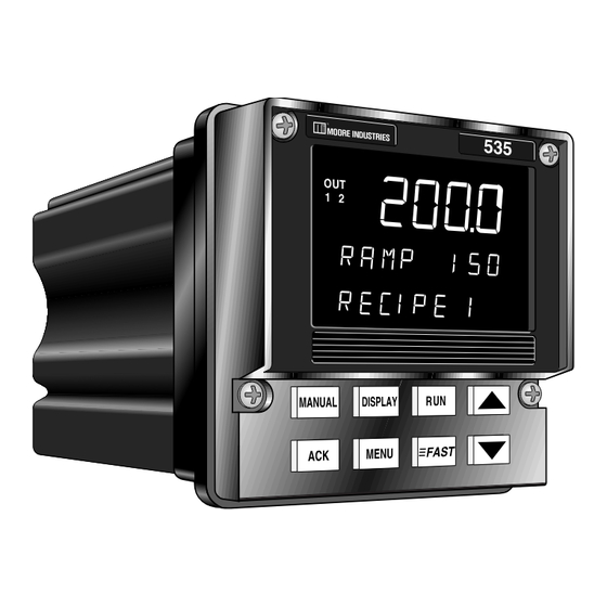
535 PROFILER
Moore 535 PROFILER Manuals
Manuals and User Guides for Moore 535 PROFILER. We have
1
Moore 535 PROFILER manual available for free PDF download: User Manual
Moore 535 PROFILER User Manual (151 pages)
Brand:
Moore
| Category:
Controller
| Size: 1 MB
Table of Contents
Chapter 1 Introduction
10
Profile Controller Modes
10
Order Code, Packaging Information
11
Where to Go Next
11
Text Formatting in this Manual
11
Table of Contents
3
Figure 3.12
9
Figure 3.5
9
Figure 6.1
9
Appendix
11
Chapter 2 Basic Interface
13
Displays
13
Icons (Lit)
14
Keys
14
Basic Profile Controller Operating Procedures
16
To Enter the RECIPE SET up Mode
16
To Enter the SET up Mode
16
To Run a Recipe
16
To Hold a Recipe
16
To Abort a Recipe and Switch to Manual Control
16
To Abort a Recipe and Control to the Idle Setpoint
16
To Display the Setpoint (SP) While a Recipe Is Running
17
To Display the Recipe Number
17
Basic Process Controller Operating Procedures
17
To Select/Change a Setpoint
17
To Change from Auto to Manual Control (Bumpless Transfer)
17
To Change from Manual to Auto
17
To Change Manual Output Values
17
To Override Security
17
To Display Control Output Value
18
To Display the Active PID Set
18
Alarm Operation
18
Alarm Indication
18
To Acknowledge an Alarm(S)
19
Latching Alarms
19
Limit Sequence
19
More on Alarms
19
Installation
20
Mounting the Controller
20
Figure 3.1
20
Figure 3.2
20
Chapter 3 Installation
20
Wiring
21
Figure 3.16
21
Figure 4.1
21
AC Power Input
22
Process Variable Input
22
Figure 3.6
23
Figure 3.6 ....... PV1 and PV2 Wiring for Milliamp, RTD and Voltage Inputs
23
Figure 3.7 ....... PV1 and PV2 Wiring for Milliamp Inputs with Internal and External Power Supply
24
Digital Input(S)
25
Digital Inputs with a Switch or Relay
25
Digital Inputs with an Open Collector
25
Figure 3.10
25
Figure 3.8
25
Figure 3.9
25
Remote Setpoint Option
25
Output Modules
26
Mechanical Relay Output
26
Solid State Relay (Triac) Output
26
Figure 3.11
26
DC Logic (SSR Drive) Output
27
Milliamp Output
27
Position Proportioning Output
27
Figure 3.13
27
Figure 3.14
27
Figure 3.15
27
Figure 4.3
27
Serial Communications
28
Limit Control
29
Chapter 4 Hardware Set up
30
Hardware Input Types
30
The Process Variable
30
The Remote Setpoint
31
Mechanical Relays
31
Accessing and Changing Jumpers
32
Adding and Changing Output Modules
33
Appendix
34
Special Communications Module
35
Software Configuration
36
Menus
36
Chapter 5 Software Configuration
36
Parameters
38
Configuration and Operation
38
Where to Go Next
38
Software Menus and Parameters
40
Config
40
Figure 3.4
41
Figure 4.4
41
Rec. Conf
46
Pv1 Input
48
Pv2 Input
50
Cust. Linr
52
Control
53
Alarms
55
Rem. Setpt
59
Retrans
60
Self Tune
62
Special
63
Security
65
Ser. Comm
66
Recipe
67
Parameter Value Charts
70
Chapter 6 Tuning
80
Overview
80
Tuning Parameters
81
Tuning Value Chart
85
Self Tune Messages and Troubleshooting
87
Applications
88
Profile Control
88
Chapter 7 Applications
88
Software Configuration
89
Digital Inputs
93
Master/Slave Operation
93
Hardware Configuration
94
Control Type
94
Software Configuration
94
Alarms
95
Software Configuration
95
Figure 7.2 ....... Alarm Examples
98
Duplex Control
99
Hardware Configuration
99
Software Configuration
99
Duplex Output State Examples
100
Duplex with Reverse and Direct Acting Outputs
100
Duplex with Direct and Reverse Acting Outputs
100
Figure 7.3
100
Figure 7.4
100
Duplex with 2 Reverse Acting Outputs
101
Duplex with a Gap between Outputs
101
Figure 5.1
101
Figure 7.5
101
Figure 7.6
101
Duplex with a Overlapping Outputs and Output Limits
102
Duplex with Various Relative Gain Settings
102
Figure 2.1
102
Figure 2.2
102
Figure 3.3
102
Figure 7.7
102
Figure 7.8
102
Duplex with One On/Off Output
103
Duplex with Two On/Off Outputs
103
Figure 7.9
103
Slidewire Position Proportioning Control
104
Hardware Configuration
104
Software Configuration
104
Velocity Position Proportioning Control
105
Hardware Configuration
105
Software Configuration
105
Staged Outputs
106
Hardware Configuration
106
Software Configuration
106
Retransmission
106
Digital Inputs
107
Hardware Configuration
107
Software Configuration
107
Basic Operating Procedures
109
Remote Setpoint
109
Hardware Configuration
109
Software Configuration
109
Basic Operating Procedures
110
Multiple Setpoints
110
Software Configuration
110
Multiple Sets of PID Values
110
Basic Operating Procedures
111
Using with Adaptive and Pretune
111
Powerback
111
Software Configuration
112
Self Tune-Powertune
112
Pretune
112
Adaptive Tune
112
Software Configurations
113
Pretune by Itself
113
Pretune Type 1 & Adaptive Tune
113
Adaptive Tune
114
Pretune Type 2 or 3 & Adaptive Tune
115
Adaptive Tune by Itself
115
Figure 5.3
116
Figure 7.1
116
Figure 7.14...... Noise Band Calculation Example
116
Self Tuning with Multiple Sets of PID
117
Self Tune with Time Proportioning Outputs
117
Self Tune with Control Valves
117
Ramp-To-Setpoint
118
Software Configuration
118
Input Linearization
118
Thermocouple and RTD Linearization
118
Square Root Linearization
118
Hardware Configuration
119
Software Configuration
119
Custom Linearization
119
Load Line
120
Security
120
Software Configuration
120
Basic Operating Procedures
121
Reset Inhibition
121
Software Configuration
121
Process Variable Reading Correction
121
Serial Communications
122
Hardware Configuration
122
Software Configuration
122
Cascade Control
123
Figure 7.2
124
Hardware Configuration
125
Software Configuration
125
Tuning Cascade Control
125
Ratio Control
126
Hardware Configuration
127
Software Configuration
127
Appendix 1
128
Menu Flowcharts
128
Appendix 2
130
Parts List
130
Appendix 3 Troubleshooting
131
Appendix 4 Calibration
133
Preparation for All Input Calibrations
134
Thermocouple Cold Junction Calibration
135
Analog Milliamp Input Calibration
135
Milliamp Output Calibration
136
Reset Menu Data
137
Hardware Scan
138
Slidewire Test
138
Quick Calibration Procedure
138
Appendix 5 Specifications
139
Appendix 6 Glossary
144
Appendix 6
144
Isolation Block Diagram
150
Advertisement
Advertisement
Related Products
Moore 5400
Moore 5500
Moore Categories
Farm Equipment
Media Converter
Controller
Fan
Power Supply
More Moore Manuals
Login
Sign In
OR
Sign in with Facebook
Sign in with Google
Upload manual
Upload from disk
Upload from URL