Atari 130XE Service Manual
Xe series
Hide thumbs
Also See for 130XE:
- Users handbooks (347 pages) ,
- Owner's manual (143 pages) ,
- Installation instructions (4 pages)
Table of Contents
Advertisement
Quick Links
Advertisement
Table of Contents

Related Manuals for Atari 130XE


Summary of Contents for Atari 130XE
-
Page 2: Table Of Contents
Equipment Needed Self Test MEMORY TEST Screen AUDIO VISUAL TEST Screen KEYBOARD TEST Screen ALL TESTS Using the ATARI REV. 3.2 Production Test Cartridge COLOR BAR TEST ANY VIDEO TEST GRAY BAR TEST DISPLAY OPTIONS RAM TEST 130XE Personal Computer... - Page 3 Expansion Slot Pin Assignments 1-13 1-16 Monitor Jack Pin Assignments 1-13 Atari 130XE 16 X 4164 Assembly CO70065/CO70067 CO7065/CO70067 PCB Atari 130XE SECAM CO70052 Rev. 2 PCB Atari 130XE SECAM Atari 130XE 4 X 4464 Assembly CA200519 130XE Personal Computer...
- Page 4 CA200519 PCB Atari 65XE 8 X 4164 Assembly CO70025 CO70025 PCB Atari 65XE 8 X 4164 Assembly CA20097 2-10 CA20097 PCB 2-11 Atari 65XE/800XE 2 X 4464 Assemblies CA200519 2-12 2-10 65XE/800XE CA200519 PCB 2-13 2-11 XE-System Assembly C100417 2-14...
-
Page 5: Introduction
The Atari 130XE Personal Computer Field Service Manual is a reference guide for the service technician. Since the XE series has more models, so on the basis of the 130XE model will also be discussed different versions 65XE computers, as well as console XE-SYSTEM . -
Page 6: Theory Of Operation
SECTION 1 THEORY OF OPERATION The Atari 130XE is an enhanced version of the existing Atari computer systems. It can be used with any existing Atari peripheral devices which are compatible with the 400 /800 or XL series computer, although not all are necessary. -
Page 7: User Interface
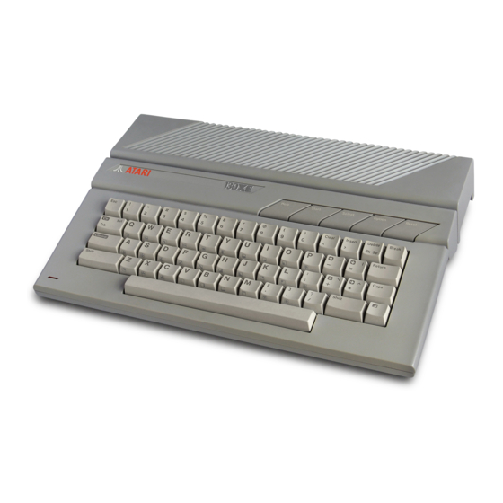
The Atari XE series are a general purpose microcomputers which uses a 6502C microprocessor. The 130XE console is the central processing unit for its respective system. The right side panel (refer to Figure 1-1) contains two controller jacks. The controller jacks accept the X-Y joystick and the paddle controllers available from Atari. -
Page 8: Mechanical Description
RESET – Interrupts and restarts the operating system or cartridge. Mechanical Description The 130XE computer console contains a single motherboard which houses all the chips of the system and provides connectors for interfacing external modules to the console. It includes the CPU, ANTIC, GTIA, POKEY, PIA, FREDDIE, RAM, ROM Operating System, and includes all functions. - Page 9 MMU1 CO61618 MAIN 64k POKEY O.S. BANK 64k BASIC Modulator Joysticks Connector Paddles Address Bus Data Bus Keyboard Control Bus RAM Addresses SIO Signals Function Keys Other signals Figure 1-4. 130XE Functional Block Diagram. 130XE Personal Computer Field Service Manual...
-
Page 10: Digital Hardware
• True indexing Stack pointer • Two interrupt levels 64K address range • Integral clock circuit • Single +5 volt DC power Requirement Figure 1-4 is an illustration of the 6502C CPU Pin Assignments. 130XE Personal Computer Field Service Manual... -
Page 11: Alphanumeric Television Interface Controller
The ANTIC Display Processor is a custom display microprocessor with an instruction set customized for graphics generation. It also has the ability to control bus and RAM REFRESH. Figure 1-6. Display Processor Pin Assignments 130XE Personal Computer Field Service Manual... -
Page 12: Graphics Television Interface Adaptor (Gtia)
POT Keyboard Integrated Circuit (POKEY) The POKEY is a Custom Large Scale Integrated Circuit (LSI) chip. It is used for audio generation, Serial Input/Output (SIO) control, controller interface scan and keyboard scan. Figure 1-8. POKEY pin assignments 130XE Personal Computer Field Service Manual... -
Page 13: Peripheral Interface Adaptor (Pia)
Peripheral Interface Adaptor (PIA) The PIA is a general purpose Input/Output (I/O) chip. Figure 1-9. PIA pin assignments FREDDIE Freddie is the controller of memory and generates a clock signal to CPU. Figure 1-10. Freddie pin assignments 130XE Personal Computer Field Service Manual... -
Page 14: Memory (Rom And Ram)
Memory The 130XE operating system is resident to 16k X 8 ROM. The ROM input CPU address lines A0 through A13 and the chip selects from the MMU, generates data on CPU data lines D0 through D7. RAM is organized as 16 X 64k x 1 or 4 X 64k X 4 chips, two for each data line. -
Page 15: System Interface
• The LED board interface Serial Input/Output (SIO) Interface The Atari 130XE communicates with peripheral devices over an asynchronous serial port (19.2K Baud Rate Max). Data is transmitted and received as 8 bits of serial data (LSB sent first) preceded by a logic zero start bit and succeeded by a logic one stop bit. The serial data out is transmitted as positive logic. -
Page 16: Controller Jack Interface
Figure 1-12. SIO Interface Pin Assignments (looking into jack on unit) External view Controller Jack Interface The 130XE provides two controller jack interfaces. Both are functionally and electrically identical. The controller jacks are 9-pin D-type connectors. 1. (Joystick) Forward Input 6. -
Page 17: Figure
A11 Address Bus !S5 Select A10 Address Bus Vcc +5V R/!W Read/Write RD5 Input from cartridge ø !CCTL Cartridge Enable 2 Buffered Phase 2 Figure 1-14. Cartridge Interface Pin Assignment (!) Signal active LOW 130XE Personal Computer Field Service Manual 1-12... -
Page 18: Monitor Jack Pin Assignments
(!) Signal active LOW Monitor Jack Figure 1-16. Monitor Jack Pin Assignment Pin 1 Monochrome VideoOutput Pin 2 GND Ground Pin 3 Audio Output Pin 4 Composite Video Output Pin 5 Color Output 130XE Personal Computer Field Service Manual 1-13... -
Page 19: Schematics And Pictures
SECTION 2 SCHEMATICS AND PICTURES The schematics and silkscreens for the 130XE, originally they were attached to the cover of this manual, but due to the poor condition of copies have been redesigned and presented in this chapter. Minor variations in design may be encountered depending upon the production date of the console. -
Page 20: Atari 130Xe 16 X 4164 Assembly Co70065/Co70067
Figure 2-1. Schematic Atari 130XE 16 X 4164 Assembly CO70065/CO70067 130XE Personal Computer Field Service Manual... - Page 21 Figure 2-2. CO70065/CO70067 PCB 130XE Personal Computer Field Service Manual...
-
Page 22: Atari 130Xe Secam
Figure 2-3. Schematic Atari 130XE SECAM CO70050 130XE Personal Computer Field Service Manual... - Page 23 Figure 2-6. 130XE SECAM CO70050 Rev.2 PCB 130XE Personal Computer Field Service Manual...
-
Page 24: Atari 130Xe 4 X 4464 Assembly Ca200519
Figure 2-5. Atari 130XE 4 X 4464 Assembly CA200519 130XE Personal Computer Field Service Manual... -
Page 25: Ca200519 Pcb
Figure 2-6. 130XE C103579/CA200519 PCB 130XE Personal Computer Field Service Manual... -
Page 26: Atari 65Xe 8 X 4164 Assembly Co70025
Figure 2-7. Atari 65XE 8 X 4164 Assembly CO70025 130XE Personal Computer Field Service Manual... -
Page 27: Co70025 Pcb
Figure 2-8. 65XE CO70025 PCB 130XE Personal Computer Field Service Manual... - Page 28 Figure 2-9. Atari 65XEN 8 X 4164 Assembly CA20097 130XE Personal Computer Field Service Manual 2-10...
-
Page 29: Ca20097 Pcb
Figure 2-8. 65XEN CA20097 PCB 130XE Personal Computer Field Service Manual 2-10... - Page 30 Figure 2-11. Schematic Atari 65XE/800XE 2 X 4464 Assembly CA200519 130XE Personal Computer Field Service Manual 2-12...
-
Page 31: Xe/800Xe Ca200519 Pcb
Figure 2-12. 65XE/800XE CA200519 PCB 130XE Personal Computer Field Service Manual 2-13... -
Page 32: Xe-System Assembly C100417
Figure 2-13. XE-System Assembly C100417 130XE Personal Computer Field Service Manual 2-14... -
Page 33: C100417 Pcb
Figure 2-14. C100417 PCB 130XE Personal Computer Field Service Manual 2-15... -
Page 34: Xe Keyboard Matrix
Figure 2-15. XE Keyboard Matrix. Line numbers are pin numbers of keyboard connector J8. 130XE Personal Computer Field Service Manual 2-16... - Page 35 Figure 2-16. PCB and Shields Assembly 130XE Personal Computer Field Service Manual 2-17...
-
Page 36: Testing
SECTION 3 TESTING OVERVIEW This section describes the procedures available for testing the 130XE. They are: • Self Test • Using Atari 65/130XE R.2 Diagnostic Cartridge EQUIPMENT NEEDED • a 130XE console with accessories a TV set, properly adjusted •... -
Page 37: Memory Test Screen
If the ROM or RAM tests defective, the color changes to red. Once a ROM or RAM has been tested and found defective the bar remains red and is not tested again on subsequent test passes. 130XE Personal Computer Field Service Manual... -
Page 38: Audio Visual Test Screen
The channel number changes for each according to the sound channel in use. Voice #1-4 under the staff and treble clef indicates the channel in use. There is a slight pause between each voice. Figure 3-3. AUDIO-VISUAL Test display 130XE Personal Computer Field Service Manual... -
Page 39: Keyboard Test Screen
RESET key is pressed. NOTE: When All Tests is executing, the MEMORY Test and the AUDIO-VISUAL Test exit after a complete test cycle. KEYBOARD Test during All Tests is software controlled. No operator input is required. 130XE Personal Computer Field Service Manual... -
Page 40: Select Screen
USING THE ATARI 65/130XE REV. 3.4 TEST CARTRIDGE Procedure: Connect the 130XE console to the TV set as shown in the Operators Manual. Insert the ATARI 65/130XE R.2 Test Cartridge in the cartridge slot and Test Loopbacks into proper jacks. Turn on the computer and TV set. - Page 41 9 color registers representing the players, missiles, and playfields against a gray background. The middle of the screen shows 4 players and 4 missiles (one color) moving up and down 1 scan line. The bottom of the screen shows a color tuning bar. 130XE Personal Computer Field Service Manual...
-
Page 42: Video Test Display
The top of the screen will go blank until the test is completed. PASS or FAIL will be printed. If the test fails, one or more error codes will be displayed. Make note of the error code and press the space bar to continue with the next test. 130XE Personal Computer Field Service Manual... -
Page 43: Port Test Display
36 error 35 can not occur - POKEY damaged or IRQ line to the processor or the processor itself. 37 Joystick port error. Socket is damaged, the lines connecting them to the PIA or PIA. 38 Damage to potentiometric inputs. Damaged socket, connecting lines or POKEY. 130XE Personal Computer Field Service Manual... -
Page 44: Keyboard Test Display
To reset the test, push START, or to continue with the next test, push SELECT. Figure 3-10. KEYBOARD Test display ROM TEST The screen will display PASS of FAIL when done. Press the space bar to begin the next test. Figure 3-11. ROM Test display 130XE Personal Computer Field Service Manual... -
Page 45: Ram Test
1 (test number) 7E45=34 35 (address, data read, data expected) 1 2 3 4 5 6 7 8 (bit numbers) Figure 3-13. RAM Test Fail 130XE Personal Computer Field Service Manual... -
Page 46: Cartridge & Expansion Slot Test Fixture
VIDEO, since the operator must determine if the test passes). Finally, the operator should press the reset key to verify that it works (the screen should go blank). FOR 130XE ONLY CARTRIDGE & EXPANSION SLOT TEST FIXTURE The CARTRIDGE & EXPANSION SLOT test fixture (Fig. 3-9) insures that all traces are properly connected on the PCB. -
Page 47: Symptom Checklist
U24, L11, L12 or Games (Adjust Audio Figure 4-1) Console (Game) Switches U19, U23 Replace will not Function ROM Test Failed U12, U13, U14. U18, U22 Replace RAM Test Failed U1-U9, U7, U14, U22 Replace 130XE Personal Computer Field Service Manual... -
Page 48: Console Disassembly
8. Carefully connect keyboard and position it in keepers of bottom cover. 9. Insert and position top cover on bottom assembly. 10. Hold the assembly together, turn console upside down and attach four screws. 130XE Personal Computer Field Service Manual... -
Page 49: Keyboard Removal/Replacement
3. Insert and tighten the four screws which hold the keyboard to the top cover. 4. Attach the keyboard connector and the LED connector (Be careful not to twist the LED connector cable). COLOR ADJUSTMENT Adjustment can be made through bottom cover. 130XE Personal Computer Field Service Manual... -
Page 50: Service Bulletins
The following are brief descriptions of each classification: FIELD CHANGE ORDER A Field Change Order describes hardware or software changes to ATARI products and instructs how to implement these changes. This identifies a failure mode which affects reliability and describes a procedure to correct the failure. This procedure must be performed on all units serviced or repaired.
Need help?
Do you have a question about the 130XE and is the answer not in the manual?
Questions and answers