
Related Manuals for Minipa ET-2907


Summary of Contents for Minipa ET-2907
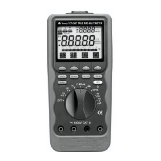
- Page 1 MULTÍMETRO DIGITAL DIGITAL MULTIMETER ET-2907 MANUAL DE INSTRUÇÕES INSTRUCTION MANUAL...
- Page 2 Advertência ! FONTES COMO PEQUENOS RÁDIO TRANSMISSORES, ESTAÇÕES DE RÁDIO E TRANSMISSORES DE TV, TELEFONES CELULARES E RÁDIO TRANSMISSORES DE AUTOMÓVEIS GERAM RADIAÇÃO ELETROMAGNÉTICA QUE PODE INDUZIR TENSÕES NAS PONTAS DE PROVA DO MULTÍMETRO. NESTES CASOS A PRECISÃO DO MULTÍMETRO NÃO PODE GARANTIDA POR RAZÕES FÍSICAS.
- Page 3 Características Gerais Tensão DC: 0 ~ 1000V Tensão AC, True RMS: 15mV ~ 1000V – largura de banda de 50kHz Precisão Básica: Tensão DC: 0.05% Tensão AC: 0.3% Corrente DC: 0 ~ 10 A (20 A por 30s) Corrente AC, True RMS: 25µA ~ 10A (20 A por 30s) Resistência: 0 ~ 50MΩ...
-
Page 4: Table Of Contents
ÍNDICE 1. INFORMAÇÕES DE SEGURANÇA ......... 05 1.1 Termos Neste Manual ............05 1.2 Símbolos Elétricos Internacionais ........06 2. COMPATIBILIDADE ELETROMAGNÉTICA (EMC) ....07 3. CONTROLES E INDICADORES ..........07 3.1 Painel Frontal ..............07 3.2 Glossário de Termos Para Multímetros Digitais ....09 4. - Page 5 5.4 Teste de Diodo ( ) ............30 5.5 Medidas de Temperatura (Temp) ......... 31 5.6 Medidas de Corrente ( ) ..........32 5.7 Característica de Advertência de Entrada Errada ....34 5.8 Operação Faixa Manual / Automática ........ 34 5.9 Buzina ................
-
Page 6: Informações De Segurança
Se o multímetro não for utilizado da maneira especificada no manual, a proteção provida pelo multímetro pode ser comprometida. O modelo ET-2907 está de acordo com as normas IEC 1010-1 (1995), UL 3111-1 (6. 1994), EN 61010-1 (1995), CSA C 22.2 nº 1010.1 – 92;... -
Page 7: Símbolos Elétricos Internacionais
Ao efetuar reparos no multímetro, utilize somente as peças de reposição especificadas. Remova as pontas de prova do multímetro antes de abrir o compartimento de bateria. Não opere o multímetro sem a tampa do compartimento de bateria. Para evitar falsas leituras, que podem resultar em choques elétricos e / ou danos pessoais, troque a bateria assim que o aviso de bateria fraca for exibido. -
Page 8: Compatibilidade Eletromagnética (Emc)
Fusível Bateria 2. COMPATIBILIDADE ELETROMAGNÉTICA (EMC) O multímetro está de acordo com EN61326: 1997 A : 1998. Leia o verso da capa deste manual. 3. CONTROLES E INDICADORES Painel Frontal Este manual descreve a operação do multímetro, com ilustrações e exemplos. -
Page 10: Glossário De Termos Para Multímetros Digitais
Glossário de Termos para Multímetros Digitais Medida Média Calibrada em RMS O termo RMS (Root-Mean-Square) é utilizado para descrever o valor efetivo ou o valor equivalente DC de um sinal AC. A maioria dos multímetros utilizam a técnica da medida média calibrada em RMS para medir valores RMS de sinais AC. - Page 11 onda puramente senoidal tem um fator de crista de 1.414. Uma forma de onda extremamente distorcida possui um fator de onda muito maior. NMRR (Razão de Rejeição no Modo Normal) NMRR é a habilidade do multímetro em rejeitar efeitos do ruído AC que podem resultar em medidas imprecisas.
-
Page 12: Visão Geral Sobre Chave Rotativa E Teclas
Mudanças não-compensadas na temperatura contribuem para a incerteza com uma certa quantia determinada pelo coeficiente de temperatura para o instrumento. Barra Gráfica Analógica A barra gráfica analógica fornece uma indicação visual da medida tal como o multímetro analógico. Isto é excelente na detecção de contatos defeituosos, identificação do passo (cliques) do potenciômetro e na indicação dos picos de sinal durante ajustes. - Page 13 Quando você gira a chave rotativa de uma função para outra, o display para a nova função é exibido. As seleções feitas pelas teclas em uma função não são transferidas para a próxima função escolhida. Desliga o multímetro. Parâmetros de configuração e medidas armazenadas são salvas.
-
Page 16: Teclas
(tensão AC+DC RMS total) R M S (corrente AC+DC RMS total) R M S / R), R=600 Ω * Saída em dBm: 10 x log(1000 x (Saída do Display Primário) * Saída em dB: 20 x log (Saída do Display Primário / rEF), rEF=1V Teclas As teclas acionam características que modificam a função selecionada com a chave rotativa. - Page 17 Pressione no menu a tecla -. O LCD irá exibir os indicadores 1ms e MIN, e os indicadores + e EXIT serão exibidos no menu de seleção; e o multímetro irá exibir o mínimo valor medido no display. Pressione a tecla de menu + para medir o valor máximo novamente, se você...
- Page 18 modo HOLD é ativado, o multímetro emite um aviso sonoro, congela o display, e exibe o indicador HOLD no LCD. O modo HOLD congela o display para posterior visualização. Auto Hold Para ativar o modo Auto Hold, pressione a tecla HOLD duas vezes até que os indicadores A- e Hold apareçam no LCD.
-
Page 19: Teclas De Seleção Do Menu
Clear: Selecione Clear para limpar todos os valores armazenados. Quando você pressionar a tecla Clear, o display exibirá um pedido de confirmação: , e os comandos AC (All Clear), Clear e Exit serão exibidos na tela do menu. Quando a tecla Clear (disponível so- mente na função RECALL) é... - Page 20 o ciclo completo de configuração for terminado. O multímetro exibirá ao final do ciclo de configuração. Os valores da configuração serão salvos numa EEPROM, então os dados não serão perdidos quando o multímetro for desligado. 1- Ativar ou Desativar o modo Auto Power Off O multímetro exibe no display secundário, ) no...
- Page 21 5- Ativar ou Desativar a iluminação de fundo ao ligar o multímetro O multímetro exibe no display secundário, ) no display primário, +, - e EXIT no menu de opções.Você pode alternar entre pressionando as teclas + / - no menu. Pressione EXIT para acessar o próximo item a ser configurado.
-
Page 22: Comunicação Rs-232 Entre O Pc E O Multímetro
Comunicação RS-232 entre o PC e o Multímetro O multímetro é equipado com uma porta para interface com isolação óptica no topo do multímetro, para comunicação de dados. O adaptador RS-70 e o software WS-70 são requeridos para conectar o multímetro ao PC. -
Page 23: Medidas De Tensão ( )
Medidas de Tensão ( As faixas disponíveis na função de tensão são: 50.000mV, 500.00mV DC e 500.00mV AC ã á á i l i ã ç ã 5.0000V, 50.000V, 500.00V, 1000.0V ã á á ã ç ã ã ã * Leitura em dBm = 10 x log (leitura do display primário / R), onde R = 600Ω... -
Page 24: Medidas De Tensão Ac
Quando medir tensão, o multímetro atua como uma impedância de 10MΩ em paralelo com o circuito. Este efeito de carga pode causar erros de medida em circuitos de alta impedância. Na maioria dos casos, o erro é desprezível (0,1% ou menos) se o circuito possuir uma impedância de 10kΩ... -
Page 25: Medidas De Tensão Dc
5.1.3 Medidas de Tensão DC Todas as características das teclas estão disponíveis para uma leitura padrão de tensão DC. 5.1.4 Medidas de Tensão DC e AC Quando a função tensão DC é selecionada, o multímetro pode exibir o valor da combinação DC+AC (RMS) ou as componentes AC e DC do sinal separadamente utilizando a tecla 4 do menu de seleção. -
Page 26: Medidas De Freqüência
Outra característica útil deste multímetro é o modo de display duplo AC DC. Tensões AC em fontes de alimentação podem causar problemas em circuitos eletrônicos. Se o multímetro estiver ajustado na posição de tensão DC, o display mostrará a componente DC de 6.0000V, Entretanto, a componente AC pode ser perdida. -
Page 27: Medidas De Duty Cycle
O padrão do multímetro para trigger no modo de medida de freqüência é a borda negativa (-). Quando o trigger é ajustado para a borda positiva, pressionando a tecla 4 do menu, é exibido no display secundário. Você pode ativar o Duty Cycle negativo ou positivo pressionando a tecla 4 do menu. -
Page 28: Medidas De Largura De Pulso
Duty Cycle Positivo: %duty = a/b x 100 (acima do ponto de trigger) Duty Cycle Negativo: %duty = (1 - a/b) x 100 (abaixo do ponto de trigger) 5.2.2 Medidas de Largura de Pulso A função medida de largura de pulso permite a medida do tempo em que um sinal é... -
Page 29: Teste De Continuidade
Dicas para Medida de Resistência Como a corrente de teste que flui através de todos os caminhos possíveis entre as pontas de prova, o valor medido de um resistor no circuito é freqüentemente diferente do valor especificado do resistor. As pontas de prova podem adicionar de 0.1Ω a 0.2Ω de erro nas medidas de resistência. -
Page 30: Medidas De Capacitância
ã r á r á Ω i t n Condutância para Testes de Alta Resistência A condutância, o inverso da resistência, indica a capacidade do circuito em deixar passar a corrente. Altos valores de condutância correspondem a baixos valores de resistência. A unidade de condutância é... -
Page 31: Teste De Diodo ( )
ã r á r á â t i â t i Dicas Para Medida de Capacitância Para agilizar a leitura de valores similares, pressione a tecla RANGE para selecionar manualmente a faixa apropriada. Para medir pequenos valores de capacitância precisamente, pressione a tecla REL com as pontas de prova em aberto para subtrair o residual de capacitância do multímetro e das pontas de prova. -
Page 32: Medidas De Temperatura (Temp)
ã r á r á ã ç A queda de tensão típica para um diodo de silício em bom estado está entre 0.4V e 0.9V. Uma leitura maior indica um diodo defeituoso ( aberto). Uma leitura igual a zero indica um diodo em curto. Uma leitura de indica um diodo aberto. -
Page 33: Medidas De Corrente ( )
* Tenha certeza de que o plugue banana do termopar tipo K esteja conectado com a polaridade correta + / - . Você pode ainda utilizar um adaptador para termopar (opcional) para adaptar outras pontas para medida de temperatura do padrão tipo K. Medidas de Corrente ( Advertência Nunca meça corrente em um circuito no qual o potencial entre o... - Page 34 (Corrente total AC+DC RMS) R M S Para medir corrente AC ou DC: Desligue a alimentação do circuito e descarregue todos os capacitores. Insira a ponta de prova preta no terminal COM e a ponta vermelha no terminal de entrada apropriado para a faixa de medida como na tabela a seguir.
-
Page 35: Característica De Advertência De Entrada Errada
Característica de Advertência de Entrada Errada Se o display mostrar ou Fuse, assegure-se de que o instrumen- to esteja configurado corretamente e teste os fusíveis do instrumento como descrito no item 6.2 “Detecção Automática de Fusível”. Se a chave rotativa não for corretamente selecionada para uma das posi- ções de medida de corrente, o alarme sonoro será... -
Page 36: Auto Power Off
5.10 Auto Power Off A característica de Auto Power Off possui dois passos. No primeiro passo o instrumento entra automaticamente no modo de economia de energia para aumentar a vida da bateria, após aproximadamente 15 minutos sem atividade. Quando o instrumento entrar no modo de economia de energia, a buzina tocará... -
Page 37: Detecção Automática De Fusível
Limpe os terminais de entrada como a seguir: Desligue o instrumento e remova as pontas de prova. Retire qualquer sujeira que possa estar presente nos terminais. Umedeça um pedaço de algodão com álcool e passe o algodão ao redor de cada terminal. Se o instrumento não vai ser utilizado por períodos maiores que 60 dias, remova a bateria e armazene-a separadamente. -
Page 38: Solucionando Problemas
Gire a chave rotativa para a posição OFF e remova as pontas de prova dos terminais de entrada. Remova a tampa do compartimento da bateria usando uma chave de fenda. Troque a bateria ou os fusíveis SOMENTE pelos especificados. Reinstale a tampa do compartimento da bateria usando a chave de fenda. -
Page 39: Especificações
7. ESPECIFICAÇÕES Segurança & Conformidade Máxima tensão entre qualquer terminal e o terra: ... 1000V AC / DC. Conformidade: ...... De acordo com CSA C22.2 No 1010.1- 92, ANSI / ISA-S82, 01-94 para Categoria de Sobretensão III 1000V. Certificação: ......Padrão UL & cUL (UL 3111-1 Listed) Marca CE. -
Page 40: Resumo Das Características
Umidade Relativa: ....0% a 80% à 0°C a 35°C, 0% a 70% à 35°C a 50°C. Altitude: ....... Operação - até 2000m..........Armazenamento - até 10000m. Tipo de Bateria: ....Única bateria 9V - NEDA 1604, JIS006P ou IEC 6F22. Vida da Bateria: .... -
Page 41: Características Elétricas
Teste de Continuidade: ..Alarme sonoro. Barra Gráfica Rápida: ... 25 segmentos. Memória: ......20 localizações. Duty Cycle / Largura de Pulso: ....Mede o tempo que o sinal está ON ou OFF em % ou milisegundos. Modo MIN/MAX: ....Registra os valores mínimo, máximo e média. - Page 42 NMRR: > 60dB em 50 / 60Hz Ω CMRR: > 120dB em DC, 50 / 60Hz, Rs=1k Ω, Ω, Impedância de Entrada: 10M 30pF nominal (50M 100pF nominal para as faixas de 50mV e 500mV) Tensão AC Ω CMRR: > 60dB em DC à 60Hz, Rs=1k Ω, Ω, Impedância de Entrada: 10M...
- Page 43 Corrente AC Tensão (AC+DC) e Corrente (AC+DC)
- Page 44 Ω Ω Ω Ω Ω Ω Ω Ω Ω Ω Ω Ω Ω Ω...
- Page 45 Capacitância (Somente 5000 Contagens) *1 Precisão utilizando capacitor de filme metálico ou melhor *2 Utilizando o modo Relativo (∆) dBm e 1ms Peak Hold (Somente 5000 Contagens) ç ã í r ã Ω Ω â ê r á Ω ± Ω...
- Page 46 Freqüência, Duty Cycle, Largura de Pulso e Temperatura Queda de Tensão (A, mA, µA) ã ç ã p í µ µ µ µ µ µ µ...
-
Page 47: Acessórios
8. ACESSÓRIOS Após receber seu instrumento, verifique a a existência dos seguintes ítens: • Manual de Instruções • Par de Pontas de Prova • Cabo da Interface RS-232 • Disquete de 3.5” • Termopar Tipo K • Garras Jacaré • Bateria 9V... -
Page 48: Garantia
5- Caso o instrumento contenha software, a Minipa garante que o software funcionará realmente de acordo com suas especificações funcionais por 90 dias. A Minipa não garante que o software não contenha algum erro, ou de que venha a funcionar sem interrupção. - Page 49 O cadastramento pode ser feito através de um dos meios a seguir: - Correio: Envie uma cópia do certificado de garantia devidamente pre- enchido pelo correio para o endereço. Minipa Indústria e Comércio Ltda. At: Serviço de Atendimento ao Cliente Alamenda dos Tupinás, 33 - Planalto Paulista CEP: 04069-000 - São Paulo - SP...
- Page 50 Warning ! SOURCES LIKE SMALL HAND-HELD RADIO TRANSCEIVERS, FIXED STATION RADIO AND TELEVISION TRANSMITTERS, VEHICLE RADIO TRANSMITTERS AND CELLULAR PHONES GENERATE ELECTROMAGNETIC RADIATION THAT MAY INDUCE VOLTAGES IN THE TEST LEADS OF THE MULTIMETER. IN SUCH CASES THE ACCURACY OF THE MULTIMETER CANNOT BE GUARANTEED DUE TO PHYSICAL REASONS.
- Page 51 Basic Specifications DC Voltage: 0 to 1000V AC Voltage, True RMS: 15mV to 1000V – 50kHz bandwidth Basic Accuracy: DC voltage: 0.05% AC voltage: 0.3% DC Current: 0 to 10A (20A for 30 seconds) AC Current, True RMS: 25µA to 10A (20A for 30 seconds) Resistance: 0 to 50MΩ...
- Page 52 CONTENTS 1. SAFETY INFORMATION ............53 1.1 Terms in This Manual ............53 1.2 International Electrical Symbols ......... 54 2. ELECTROMAGNETIC COMPATIBYLITY (EMC) ....... 55 3. CONTROLS END INDICATORS ..........55 3.1 Front Panel ................ 55 3.1 Glossáry of Terms for Digital Multimeters ......57 4.
- Page 53 5.4 Diode Test (` ) .............. 78 5.5 Temperature Measurements (Temp) ........79 5.6 Current Measurements ( ) .......... 80 5.7 Wrong Input Warning Feature ..........82 5.8 Auto / Manual Range Operation ......... 82 5.9 Beeper ................82 5.10 Auto Power Off ..............83 6.
-
Page 54: Safety Information
If the meter is not used in a manner specified in this manual, the protection provided by the meter may be impaired. The Model ET-2907 comply with IEC 1010-1 (1995), UL 3111-1 (6. 1994), EN 61010-1 (1995), CSA C 22.2 No, 1010.1 - 92 ; Overvoltage 1000V Category III. -
Page 55: International Electrical Symbols
Remove test leads from the meter before you open the battery door. Do not operate the meter with the battery door removed or loosened. To avoid false readings, which could result in possible electric shock or personal injury, replace the battery as soon as the low battery indicator appears. -
Page 56: Electromagnetic Compatibylity (Emc)
Fuse Battery 2. ELECTROMAGNETIC COMPATIBILITY (EMC) The meter meet EN61326 : 1997+A1 : 1998. See the backside of this manual’s cover page. 3. CONTROLS AND INDICATORS Front Panel This manual describe the operation of multimeter, with illustrations and examples. 4-4/5 digit, 50000 (Primary display) / 5000 (Secondary display) count LCD display On screen menu selection push-buttons Push-buttons for special functions &... -
Page 58: Glossáry Of Terms For Digital Multimeters
Glossary of Terms for Digital Multimeters Average sensing RMS calibrated RMS (Root-Mean-Square) is the term used to describe the effective or equivalent DC value of an AC signal. Most digital multimeters use average sensing RMS calibrated technique to measure RMS values of AC signals. - Page 59 A pure sinusoidal waveform has a Crest Factor of 1.414. A badly distorted sinusoidal waveform normally has a much higher Crest Factor. NMRR (Normal Mode Rejection Ratio) NMRR is the DMM’s ability to reject unwanted AC noise effect which can cause inaccurate DC measurements. NMRR is typically specified in terms of dB (decibel).
-
Page 60: Rotary Switch And Pushbutton Overview
Analog Bar-graph The analog bar graph provides a visual indication of measurement like a traditional analog meter’s needle. It is excellent in detecting faulty contacts, identifying potentionmeter’s clicks and indicating signal spikes during adjustments. 4. ROTARY SWITCH AND PUSHBUTTON OVERVIEW Turning the Meter On To turn the meter on, turn the rotary switch from OFF to any switch setting. - Page 61 Turns the meter off. Setup parameters and stored measurements are saved. Millivolts AC RMS and DC measurement. Compatible with various adaptors. Volts AC RMS, Volts DC, Volts AC+DC total RMS, Volts AC DC dual display, dBm, and dB. Frequency measurement. Duty cycle and pulse width are also displayed if they are turned on in the on screen menu.
-
Page 64: Pushbuttons
(AC+DC total RMS volts) R M S (AC+DC RMS amps) R M S / R), R=600 Ω * dBm readout: 10 x log(1000 x (Primary Display Readout) * dB readout: 20 x log (Primary Display Readout / rEF), rEF=1V Pushbuttons The buttons activate features that augment the function selected with the rotary switch. - Page 65 The LCD displays the 1ms and MIN indicators and + and EXIT indicators in the on screen menu selection and the meter will display a captured minimum value. Press the + menu key to capture a maximum value again, if you want. The meter beeps when a new maximum or minimum reading is updated.
- Page 66 HOLD. Press this button to turn HOLD mode on and off. When the hold mode is activated, the meter beeps, freezes the display, and displays the HOLD indicator on the LCD. Hold mode freezes the display for later view. Auto Hold. To activate auto hold mode, press the HOLD button twice until A–...
-
Page 67: On Screen Menu Selection Keys
Clear . Select Clear to clear all the stored values. When you press Clear key, the meter will ask you with the display of along with the On Screen Menu Selections of AC (stands for ALL Clear), Clear and EXIT. When you press the Clear (availiable only in Recall option) key, the displayed value in the primary display is erased. - Page 68 1- Enable or Disable the auto-power-off mode The meter displays in the secondary display, in the primary display and +, - , EXIT in the on screen menu selection. You can toggle by pressing the +, - menu keys. Press the EXIT menu key to get into the next Setup.
-
Page 69: Rs-232 Pc-To-Meter Communications
6- Enable or Disable the beep alert warning overranges The meter displays in the secondary display, ) in the primary display and +, - , EXIT in the on screen menu selection. You can toggle by pressing the +, - menu keys. Press the EXIT menu key to get into the next Setup. -
Page 70: Meter Operation And Special Features
5. METER OPERATION AND SPECIAL FEATURES Making Measurements All measurements are made by first setting the measurement function knob to a function setting (so that the meter is put in the default measurement function) and then selecting a measurement from the menukeys. -
Page 71: Voltage Measurement ( )
Voltage Measurement ( Ranges avaliable in volts function are: 50.000mV, 500.00mV DC e 500.00mV AC 5.0000V, 50.000V, 500.00V, 1000.0V * dBm readout = 10 x log (primary display readout / R), where R = 600Ω (default) * dB readout = 20 x log (primary display readout / ref), where ref = 1V (default) -
Page 72: Ac Voltage Measurements
5.1.1 AC Voltage Measurements All pushbutton features are available in this function. The On Screen Menu Selection accesses decibel (dBm or dB) measurements. 5.1.2 dB (dBm or dB V) Measurements in AC Volts Function The AC volts function allows you to display readings as deviations in dB (decibels) above or below an established reference level. -
Page 73: Dc Voltage Measurements
5.1.3 DC Voltage Measurements All pushbutton features are available for a standard DC volts reading. 5.1.4 Both AC and DC Voltage Measurements When a DC volts function is selected, the meter can display the combined AC + DC (RMS) value or AC and DC components of a signal separately by using the On Screen Menu Selection button. -
Page 74: Frequency Measurements
When calculating the power dissipated in a circuit component, it is critical that the DC value is factored into the equation V where V is AC + DC total RMS. Another useful feature of this Meter is AC DC dual display mode. AC voltages riding on power supplies can cause problems with electronic circuits. -
Page 75: Duty Cycle Measurements
The meter defaults at negative edge triggering in the frequency measurement mode. When you set positive edge triggering by pressing the Menukey 4, is displayed in the secondary display. You can turn on positive or negative duty cycle by pressing the Menukey 4. -
Page 76: Pulse Width Measurement
Positive duty cycle : % duty = a/b x 100 (above trigger point) Negative duty cycle : % duty = (1–a/b ) x 100 (below trigger point) 5.2.2 Pulse Width Measurement The pulse width measurement function allows you to measure the amount of time a signal is high or low within a given period. -
Page 77: Continuity Test
Tips for measuring resistance Because the meter’s test current flows through all possible paths between the test probe tips, the measured value of a resistor in a circuit is often different from the resistor’s rated value. The test leads can add 0.1Ω to 0.2Ω of error to resistance mea- surements. -
Page 78: Capacitance Measurements
Ω i t n y t i ) t r Conductance for High Resistance Tests Conductance, the reverse of resistance, is the ability of a circuit to pass current. High values of conductance correspond to low values of resistance. The unit of conductance is the Siemens (S). 5.3.2 Capacitance Measurement Caution... -
Page 79: Diode ( ) Test
a t i a t i Tips for measuring capacitance To speed up measurements of similar values, press RANGE to manually select the proper range. To measure small values of capacitance accurately, press REL with the test leads open to subtract the residual capacitance of the meter and test leads. -
Page 80: Temperature Measurements (Temp)
o i t Forward Bias Reverse Bias Normal forward voltage drop ( forward biased ) for a good silicon diode is between 0.4V to 0.9V. A reading higher than that indicates a leaky (defective) diode. A zero reading indicates a shorted (defective) diode. indicates an open diode (defective). -
Page 81: Current Measurements ( )
i s l o i t C º ) t l F º Current ( ) Measurements) Warning Never attempt an in-circuit current measurement where the open-cir- cuit potential to earth is greater than 1000 V. You may damage the meter or be injured if the fuse blows during such a measurement. - Page 82 ) t l (AC+DC total RMS amps) R M S To measure AC or DC current: Turn off power to the circuit and discharge all high-voltage capacitors. Insert the black lead into the COM terminal and the red lead into an input terminal appropriate for the measurement range as the following table.
-
Page 83: Wrong Input Warning Feature
Open the circuit path to be tested. Touch the red probe to the more positive side of the break and touch the black probe to the more negative side of the break. (Reversing the leads will produce a negative reading, but will not damage the meter.) Turn on power to the circuit and read the display. -
Page 84: Auto Power Off
5.10 Auto – Power – Off The Auto-Power-Off feature has two steps. The first step has the meter automatically go into the power saving mode to extend battery life after approximately 15 minutes of no activities. When the meter enters the power saving mode, the meter beeps warning tones every minute. -
Page 85: Auto Fuse Detection
1. Turn the meter off and remove all test leads. 2. Shake out any dirt that may be in the terminals. 3. Soak a new swab with alcohol and work the swab around in each terminal. If the meter is not to be used for periods of longer than 60 days, remove the battery and store it separately. -
Page 86: Trouble Shooting
Trouble Shooting If the meter fails to operate even with the battery or fuse replacements, check it twice over according to operating procedure as described in this manual. If the meter’s V/Ω input terminal has subjected to high voltage transient (caused by lightning or switching surge to the system) by accident or abnormal operating conditions, the series fusible resistors will be blown off like fuses in order to protect the user and the meter. -
Page 87: Specifications
7. SPECIFICATIONS Safety & Compliances Maximum voltage between any terminal and earth ground: ......... 1000 V AC/DC Compliances: ....... Complies with CSA C22.2 No 1010.1- 92, ANSI/ISA-S82, 01-94 to 1000 V Overvoltage Category lll. Certifications: ....... UL & cUL standard UL 3111-1 Listed CE marking certificated Surge Protection: .... -
Page 88: Feature Summary
Battery Type: ....... Single 9V battery –NEDA 1604, JIS 006P or IEC 6F 22 Battery Life: ......150 hrs. typical (with backlight off) Shock Vibration: ....Per MIL-T-PRF 28800 for Class II instruments Pollution Degree: ....2 Electromagnetic Compatibility (EMC): .... Susceptibility – Commercial Limits for EN 50082-1 .......... -
Page 89: Electrical Specifications
MIN/MAX Mode: ....Record maximum, minimum, and average values 1ms PEAK Mode: ....Captures peaks to 1 millisecond Closed-Case Calibration: ..No internal adjustments needed Battery / Fuse Access Door: ....... Battery or fuse replaceable without voiding calibration High-Impact Overmolded Case: ....Protective holster features Electrical Specifications Accuracy is given as ±... - Page 90 NMRR: > 60dB at 50 / 60Hz Ω CMRR: > 120dB at DC, 50 / 60Hz, Rs=1k Ω, Ω, Input Impedance: 10M 30pF nominal (50M 100pF nominal for 50mV and 500mV ranges) AC Voltage Ω CMRR: > 60dB at DC to 60Hz, Rs=1k Ω, Ω, Input Impedance: 10M...
- Page 91 AC Current (AC+DC) Voltage and (AC+DC) Current...
- Page 92 Resistance Ω Ω Ω Ω Ω Ω Ω Ω Ω Ω Ω Ω Ω Ω Open Circuit Voltage: < 1.3V DC * Using Relative Mode Conductance (5000 counts only) Diode Test...
- Page 93 Capacitance (5000 counts only) *Accuracy with film capacitor or better **Using Relative Mode Frequency, Duty Cycle, Pulse Width and Temperature...
- Page 94 dBm and 1 ms Peak Hold (5000 counts only) Ω Ω Ω ± Ω e i f a t l ± Burden Voltage (A, mA, µA) µ µ µ µ µ µ µ Continuity Ω Ω <...
-
Page 95: Accessories
8. ACCESSORIES After receive this instrument verifies the existance of the following accessories: • Instructions Manual • Pair of Test Leads • RS-232 Interface Cable • 3.5” Disk • K Type Thermocouple • Alligator Tips • 9V Battery... -
Page 96: Warranty
5- For instrument with software, Minipa assumes responsibility that the software will operate in accordance with its functional specifications for 90 days. Minipa will not guarantee that the software will be error free or operate without interruption. 6- Minipa assumes no risk for damage in transit nor the transportation costs. - Page 97 - e-mail: Scanning this form and attach to your e-mail. Please send to sac@minipa.com.br. - Site: Register the warranty certificate by http://www.minipa.com.br/sac. IMPORTANT The warranty conditions and limitations will be valid only to the certificates correctly registered. In case the purchaser did not register, a sales receipt showing the date of purchase will be required.
- Page 98 Minipa Indústria e Comércio Ltda. Al. dos Tupinás, 33 - Planalto Paulista - São Paulo - CEP: 04069-000 CGC: 43.743.749/0001-31 Site: http://www.minipa.com.br...
Need help?
Do you have a question about the ET-2907 and is the answer not in the manual?
Questions and answers