Table of Contents
Advertisement
Quick Links
Download this manual
See also:
User Manual
Advertisement
Table of Contents

Subscribe to Our Youtube Channel
Related Manuals for Fluke 2638A


Summary of Contents for Fluke 2638A
- Page 1 2638A HYDRA Series III Data Acquisition Unit Calibration Manual August 2014 © 2014 Fluke Corporation. All rights reserved. Specifications are subject to change without notice. All product names are trademarks of their respective companies.
- Page 2 Fluke authorized resellers shall extend this warranty on new and unused products to end-user customers only but have no authority to extend a greater or different warranty on behalf of Fluke. Warranty support is available only if product is purchased through a Fluke authorized sales outlet or Buyer has paid the applicable international price.
-
Page 3: Table Of Contents
Table of Contents Title Page Introduction .................... 1 Contact Fluke ..................1 Safety Information ................. 2 General Specifications ................5 Measurement Specifications ..............6 DC Voltage ..................6 DC Voltage Input Characteristics ..........6 DC Voltage Accuracy ..............7 DC Voltage Additional Errors ............7 AC Voltage .................. - Page 4 Calibration Manual Totalizer ..................... 14 Trigger ....................15 Alarm Output ..................15 2638A-100 Universal Input Module ............15 General Maintenance ................16 If the Product Does Not Turn On ............16 Clean the Product ................16 Replace the Line Power Fuse ............16 Battery Replacement .................
- Page 5 List of Tables Table Title Page Symbols ..................... 2 Fuses ......................16 Memory Clear Functions ................18 Required Test Equipment ................19 DC Volts Verification Steps ............... 23 AC Volts Verification Steps ............... 25 AC Volts Frequency Verification Steps ............. 25 4-Wire Ohms Verification Steps ..............
- Page 6 2638A Calibration Manual...
- Page 7 List of Figures Figure Title Page Fuse Replacement ..................17 DC Voltage Test Connections ..............22 AC Volts Verification Connections ............. 24 4-Wire Ohms Test Equipment Setup ............26 PRT Verification Connection ..............27 Thermistor Test Equipment Setup ............. 28 mA DC Current Equipment Setup .............
- Page 8 2638A Calibration Manual...
-
Page 9: Introduction
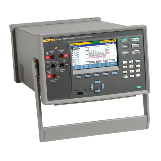
Introduction The Fluke 2638A HYDRA Series III Data Acquisition Unit (the Product or Instrument) is a 67 analog channel bench-top data logger that measures and records dc volts, ac volts, dc current, ac current, resistance, frequency, and temperature. See the Specifications section for information on the types and ranges of the measurement inputs the Product can accept. -
Page 10: Safety Information
Product Category: With reference to the equipment types in the WEEE Directive Annex I, this product is classed as category 9 "Monitoring and Control Instrumentation" product. Do not dispose of this product as unsorted municipal waste. Go to Fluke’s website for recycling information. - Page 11 HYDRA Series III Data Acquisition Unit Safety Information Warning To prevent possible electrical shock, fire, or personal injury: • Read all safety information before you use the Product. • Carefully read all instructions. • Use the Product only as specified, or the protection supplied by the Product can be compromised.
- Page 12 2638A Calibration Manual • Consider all accessible channels to be hazardous live and an electric shock hazard if any channel is connected to a hazardous voltage source. • Do not remove, touch, or change the internal wiring of hazardous inputs until the input source is turned off.
-
Page 13: General Specifications
HYDRA Series III Data Acquisition Unit General Specifications General Specifications Mains Voltage 100 V Setting ............90 V to 110 V 120 V Setting ............108 V to 132 V 220 V Setting ............198 V to 242 V 240 V Setting ............216 V to 264 V Frequency .............. -
Page 14: Measurement Specifications
2638A Calibration Manual Memory Scan data RAM........... 75,000 readings with timestamp Data/Setup flash memory ........20 MB Non-volatile memory life ........5 years USB Host Port Standard ............. 2.0, full speed Connector type ........... Type A Function .............. Memory File system ............FAT32 Memory capacity.......... -
Page 15: Dc Voltage Accuracy
HYDRA Series III Data Acquisition Unit Measurement Specifications DC Voltage Accuracy Accuracy is given as ± (% measurement + % of range). T.C./ °C 24 Hour 90 Days 1 Year Range Outside (23 ±1 °C) (23 ±5 °C) (23 ±5 °C) 18 °C to 28 °C 100 mV 0.0025 % + 0.003 %... -
Page 16: Ac Voltage Input Characteristics
2638A Calibration Manual AC Voltage Input Characteristics Resolution Range Resolution Input Impedance 4 ½ 5 ½ 6 ½ Digits Digits Digits 10 μV 1 μV 0.1 μV 100 mV 100.0000 mV 1.000000 V 100 μV 10 μV 1 μV 1 MΩ ±2 % shunted by 150 pF 10 V 10.00000 V... -
Page 17: Dc Current Input Characteristics
HYDRA Series III Data Acquisition Unit Measurement Specifications DC Current Input Characteristics Resolution Reference Burden Fast Medium Slow Range Resolution Resistance Voltage 4½ 5 ½ 6 ½ (Ohms) Digits Digits Digits 100 μA 100.0000 µA 10 nA 1 nA 0.1 nA 1k Ω... -
Page 18: Ac Current Accuracy
2638A Calibration Manual AC Current Accuracy Accuracy is given as ± (% measurement + % of range). Basic accuracy specification is for a sinusoidal signal with amplitude greater than 5 % of range. For input signals between 1 % to 5 % of range, add 0.1 % of range. -
Page 19: Resistance Input Characteristics
HYDRA Series III Data Acquisition Unit Measurement Specifications Resistance Input Characteristics Resolution Range Resolution Source Current Fast Medium Slow 4½ Digits 5 ½ Digits 6 ½ Digits 100 Ω 100.0000 Ω 1 mA / 4 V 10 mΩ 1 mΩ 0.1 mΩ... -
Page 20: Rtd Temperature Accuracy
2638A Calibration Manual RTD Temperature Accuracy Accuracy is for 4-wire 100 Ω nominal RTD, using the slow sample rate. With 3-wire PRT/RTD add 0.015 °C if using Channel 1, or add 0.15 °C internal resistance mismatch to the accuracy specification if using channels x01 through x20, and add external lead wire resistance mismatch. -
Page 21: Thermistor Measurement Characteristics
HYDRA Series III Data Acquisition Unit Measurement Specifications Thermistor Measurement Characteristics Temperature Display Resolution Range Source Current Slow Medium/Fast Sample Rate Sample Rate 0 Ω to 98 kΩ 10 μA 0.001 °C 0.01 °C 0.001 °C 0.01 °C 1 μA 95 kΩ... -
Page 22: Thermocouple Measurement Characteristics
2638A Calibration Manual 300 °C 1.32 °C 1.97 °C 1.97 °C 600 °C 0.68 °C 1.02 °C 1.02 °C 100 °C to 1820 °C 1200 °C 0.41 °C 0.60 °C 0.60 °C 1600 °C 0.38 °C 0.55 °C 0.55 °C 600 °C... -
Page 23: Trigger
HYDRA Series III Data Acquisition Unit 2638A-100 Universal Input Module Trigger Absolute Voltage Range ......... -4 V to 30 V Minimum Logic High ..........2.0 V Maximum Logic Low ..........0.7 V Minimum Pulse Width ..........50 μs Maximum Latency ........... 100 ms Alarm Output Absolute Voltage Range ......... -
Page 24: General Maintenance
3. Make sure the power source that the Product is plugged into is energized. 4. Verify that the line power fuse is good. See “Replace the Line Power Fuse”. If these steps do not solve the problem, then contact Fluke. See the “Contact Fluke”. -
Page 25: Battery Replacement
HYDRA Series III Data Acquisition Unit General Maintenance To replace the fuses, see Figure : 1. Remove any high-capacity modules or test leads from the Product where hazardous voltage may be present. 2. Disconnect the mains-power cord from the power-entry module. 3. -
Page 26: Memory And Factory Reset
2638A Calibration Manual Memory and Factory Reset The Product has two memory reset functions to remove data from the memory and reset the Product: • Clear all Files • Factory Reset See Table 3 for a comparison of these functions. -
Page 27: Required Equipment
Model Comments Standard Fluke 5720A Used to characterized the 8½ digit meter Fluke 8508A 5522A Volts DC Fluke low thermal 4-wire 4-wire short Fluke PN 2653346 short or equivalent Must be characterized with Alternate standard Fluke 5522A 8508A Standard Fluke 5720A Used to characterized the 8½... - Page 28 PTFE-insulated test cables between the test Cables equipment and the Meter. Fluke makes a 2 foot (PN 738716) and 4 foot (PN 738724) PTFE insulated test cable for this purpose Other alternate standards beside those listed can be used as long as they provide sufficient traceable [Test...
-
Page 29: Test Considerations
Product. • User the Fluke low-thermal 4-Wire short for all voltages and Ohm shorts. See Table 4 for Fluke part number. Performance Tests This section provides performance tests to verify that the Product operates within published specifications as well as a complete calibration procedure. -
Page 30: Front Panel Test
Table 5. Note For the 0 V tests, use the 4-wire short to short the Hi/Lo and Sense inputs. 5522A Calibrator 5520A CALIBRATOR 2638A HYDRA Series NORMAL SCOPE V, , ,RTD A, -SENSE, AUX V FUSED TRIG... -
Page 31: Dc Volts Verification Steps
HYDRA Series III Data Acquisition Unit Performance Tests Table 5. DC Volts Verification Steps 90-Day Test Limits 1-Year Test Limits Nominal Range Input(V) High High 3.5 μV -3.5 μV 3.5 μV -3.5 μV 0.04 40.0045 mV 39.9955 mV 40.005 mV 39.995 mV 100.006 mV 99.994 mV... -
Page 32: Volts Ac And Frequency Verification
Connect the Product to the test equipment as shown in Figure 3 and apply the voltages listed in Table 6 and Table 7. 5522A Calibrator 5520A CALIBRATOR 2638A HYDRA Series NORMAL SCOPE V, , ,RTD A, -SENSE, AUX V FUSED... -
Page 33: Ac Volts Verification Steps
HYDRA Series III Data Acquisition Unit Performance Tests Table 6. AC Volts Verification Steps Nominal Input 90-Day Test Limits 1-Year Test Limits Range Ampl. Freq. High High 100.0 mV 20 Hz 100.16 mV 99.84 mV 100.16 mV 99.84 mV 100.0 mV 20 kHz 100.16 mV 99.84 mV... -
Page 34: 4-Wire Ohms Verification
2638A Calibration Manual 4-Wire Ohms Verification Connect the Product to the test equipment as shown in Figure 4 and apply the resistance listed in Table 8. Note Ω For the 0 tests, use the 4-wire short to short the Hi/Lo and Sense inputs. -
Page 35: Prt Verification Steps
HYDRA Series III Data Acquisition Unit Performance Tests PRT Verification Steps Connect the Product as in Figure 5 for the 1 kΩ value listed in Table 9. For all other values in the table, use standard resistors. Configure the Ch001 as 4-wire PRT function with resistance display. -
Page 36: Thermistor Verification Steps
2638A Calibration Manual Thermistor Verification Steps Connect the Product to the test equipment as shown in Figure 6 and apply the resistance listed in Table 10. Configure Ch001 as a 4-wire thermistor function with resistance display. 5522A Calibrator hcn304.eps Figure 6. Thermistor Test Equipment Setup... -
Page 37: Dc Current Verification
When the 5720A/5522A is used as source, connect Hi (source) to Lo (Product) and Lo (source) to mA (Product). For the 0 A tests, open Lo inputs. 5522A Calibrator 5520A CALIBR ATOR 2638A HYDRA Series NORMAL SCOPE V, , , RTD A, -SENSE, AUX V... -
Page 38: Dc Current Verification Steps
2638A Calibration Manual Table 11. DC Current Verification Steps Nominal 90-Day Test Limits 1-Year Test Limits Range Input High High (mA) 3.5 nA -3.5 nA 3.5 nA -3.5 nA 100.0185 μA 99.9815 μA 100.0185 μA 99.9815 μA -99.9815 μA -100.0185 μA -99.9815 μA... -
Page 39: Ac Current Verification Steps
When use 5720A/5522A as source, connect Hi (source) to Lo (meter) and Lo (source) to mA (meter). For the zero (0) A tests, open Lo inputs. 5522A Calibrator 5520A CALIBR ATOR 2638A HYDRA Series NORMAL SCOPE V, , , RTD A, -SENSE, AUX V... -
Page 40: 2638A-100 Module Verification
100.36 mA 99.64 mA [1] 5522A must be used with 8508A to obtain suitable test uncertainty ratio. 2638A-100 Module Verification 1. Connect the calibrated E-type thermocouples to channel 10 on the Product (UUT). 2. Insert the thermocouples into a drywell calibrator which is set and stabilized at 25 °C. -
Page 41: Calibration Adjustment
A simple adjustment program is listed in the Sample Adjustment Program section. A MetCal program is available at www.fluke.com to adjust the Product. Adjustments are password protected to prevent accidental or unauthorized adjustments. -
Page 42: Reset The Admin Password
2638A Calibration Manual Reset the Admin Password If the admin password is lost or forgotten, the password can be reset to 2638 with these steps: Note Before doing these steps, try to use the factory default password: 2638. 1. Do the general disassembly steps in the “Disassembly” section. -
Page 43: Disassembly
HYDRA Series III Data Acquisition Unit Calibration Adjustment Disassembly Warning To prevent possible electrical shock or personal injury, disconnect the mains power cord before you remove the Product covers. Only disassemble the Product to reset the password or replace the battery. See Figure 10. - Page 44 2638A Calibration Manual Boot Removal To Remove, Pull End From Unit Battery hcn309.eps Figure 10. Disassembly...
-
Page 45: Change The Calibration Date Remotely
HYDRA Series III Data Acquisition Unit Calibration Adjustment Change the Calibration Date Remotely The calibration date is automatically updated when the “CALibrate:STORe” command is sent. “Mainframe” Adjustment Process Table 13 lists: • Step numbers • Description of the adjustment • Measurement adjustment type (open, zero, or gain adjustment) •... - Page 46 2638A Calibration Manual Table 13. Adjustment Steps (cont.) Value Entry Step Input Signal Description Range Point AC_2_5V_3 2.5 V, 1 kHz AC_0_5V_3 0.5 V, 1 kHz AC_0V_3 0.0 V Start calibration of ac AC100V 100.0 100 V range AC_100V_4 100.0 V, 1 kHz AC_50V_4 50.0 V , 1 kHz...
- Page 47 HYDRA Series III Data Acquisition Unit Calibration Adjustment Table 13. Adjustment Steps (cont.) Input Entry Step Value Range Description Signal Point DC_N10V_3 -10.0 V Start calibration of dc 100 V DC100V 100.0 range DC_P100V_4 100.0 V DC_0V_4 0.0 V DC_N100V_4 -100.0 V Start calibration of dc 300 V DC300V...
- Page 48 2638A Calibration Manual Table 13. Adjustment Steps (cont.) Input Entry Step Value Range Description Signal Point 0.0 Ω R_0_4 Start calibration of FRES 1.0E+6 1 MΩ range R_1M_5 1.0 MΩ R_190K_5 190.0 kΩ R_100K_5 100.0 kΩ 0.0 Ω R_0_5 Start calibration of RES R10M 10.0E+6...
- Page 49 HYDRA Series III Data Acquisition Unit Calibration Adjustment Table 13. Adjustment Steps (cont.) Input Entry Step Value Range Description Signal Point T_1M_3 1.0 MΩ T_190K_3 190.0 kΩ T_100K_3 100.0 kΩ 0.0 Ω T_0_3 Start calibration of HZ1K frequency 1000.0 Hz, HERTZ Start calibration of ac AC100UA...
- Page 50 2638A Calibration Manual Table 13. Adjustment Steps (cont.) Entry Step Value Range Input Signal Description Point AC_5MA_3 5.0 mA, 500 Hz AC_2_5MA_3 2.5 mA, 500 Hz AC_0_5MA_3 0.5 mA, 500 Hz AC_0A_3 Open Start calibration of ac AC100MA 100.0E-3 100 mA range 100.0 mA,...
-
Page 51: Remote Commands For Calibration
HYDRA Series III Data Acquisition Unit Remote Commands for Calibration Remote Commands for Calibration Table 14 alphabetically lists the command set for calibration. Table 14. List of Commands Remote Command Meaning Instruct unit to abort calibration procedure after CALibrate:ABORt present step. Backup to previous entry point in calibration CALibrate:BACKup procedure. -
Page 52: Remote Programming Examples
2638A Calibration Manual Remote Programming Examples This section gives examples of command sequences for several likely scenarios. Start a Full Calibration Table 15 shows an example to run a full calibration. Table 15. Full Calibration Example Command Action Disable the security for calibration. -
Page 53: Calibrate 1 V Dc Range Only
HYDRA Series III Data Acquisition Unit Remote Commands for Calibration Calibrate 1 V DC Range only Table 16 shows an example to run a calibration for 1 V dc. Table 16. 1 V DC Calibration Example Command Action Disable the security for calibration. CAL:SEC:STAT OFF,”2638”... -
Page 54: Command References
2638A Calibration Manual Command References CALibrate:ABORt Description: Instruct unit to abort calibration procedure after present step. Example: CAL:ABOR Related Commands: CALibrate:STATe? CALibrate:BACKup Description: Backup to previous entry point in calibration procedure. Example: CAL:BACK Related Commands: CALibrate:SKIP CALibrate:SECTion CALibrate:CONSt? “<cco_name>” Description: Retrieves the value in use of the given calibration constant. - Page 55 HYDRA Series III Data Acquisition Unit Remote Commands for Calibration CALibrate:INFOrmation? Description: Return message or instructions associated with running step Example: CAL:INFO? Response: “Connect calibrator to Volt terminals” Related Commands: CALibrate:STATe? CALibrate:STEP? CALibrate:MODule:DATE <slot>,<year>,<month>,<day> CALibrate:MODule:DATE? <slot> Description: Set and query module calibration date. Example: CAL:MOD:DATE 1,2013,11,1 CAL:MOD:DATE? 1...
- Page 56 2638A Calibration Manual CALibrate:REFerence? Description: Return nominal value expected for reference entry Example: CAL:REF? Response: 3.000000e+00 Related Commands: CALibrate:NEXT CALibrate:STATe? CALibrate:INFOrmation? CALibrate:STEP? CALibrate:SECure:STATe <boolean>, <admin_password> Description: Instruct unit to enable calibration Example: CAL:SEC:STATE OFF,”1586” Related Commands: CALibrate:SECure:STATe? CALibrate:SECure:STATe? Description: Query calibration enable state...
- Page 57 HYDRA Series III Data Acquisition Unit Remote Commands for Calibration CALibrate:STARt <procedure>[,<step>] Description: Start a calibration procedure. As parameter, the name of procedure should be provided (MAIN is the procedure for full instrument calibration), an optional parameter <step> can be provided to start from, if it is omitted, it starts at the beginning.
- Page 58 2638A Calibration Manual CALibrate:STEP? Description: Return name of step currently running Example: CAL:STEP? Response: DC1V Related Commands: CALibrate:STATe? CALibrate:REFerence? CALibrate:INFOrmation? CALibrate:STORe CALibrate:STORe? Description: Store new calibration constants or query whether a cal store is nedded. Example: CAL:STOR CAL:STOR? Response: 1 is yes, 0 if no...
-
Page 59: User-Replaceable Parts And Accessories
Table 18. User-Replaceable Parts and Accessories Fluke Item Part Description Number 4281998 FLUKE-1586A-2010, 2638A HANDLE 4281980 FLUKE-1586A-2009, 2638A FRONT PANEL BOOT 4281971 FLUKE-1586A-2008, 2638A REAR PANEL BOOT 4396173 FLUKE 1586A-2586 RELAY CARD 4374731 FLUKE-1586A-2586, 2638A, PROTECTIVE SLOT COVER ... - Page 60 2638A Calibration Manual hcn310.eps Figure 11. Replaceable Parts...
Need help?
Do you have a question about the 2638A and is the answer not in the manual?
Questions and answers