Table of Contents
Advertisement
SERVICE MANUAL
Ver 1.0 2001.04
FM tuner section
Frequency range
87.5 - 108.0 MHz
(50 kHz step)
75 Ω, unbalanced
Aerial terminals
IEC-male
Intermediate frequency
10.7 MHz
Sensitivity
at 26 dB quieting (mono)
10.3 dBf, 0.9 µV/75 Ω
at 46 dB quieting (stereo)
38.5 dBf, 23 µV/75 Ω
Usable sensitivity (IHF)
10.3 dBf, 0.9 µV/75Ω
S/N
at 40 kHz deviation
74 dB (mono), 69 dB
(stereo)
Harmonic distortion
0.09% (mono),
0.18% (stereo)
Frequency response
30 Hz - 15 kHz
(+0.5/–1.0 dB)
Separation
45 dB at 1 kHz
Selectivity
at 400 kHz
85 dB
at 300 kHz
70 dB
Output
at 40 kHz deviation
600 mV
Sony Corporation
9-873-834-11
2001D0500-1
Home Audio Company
C 2001.4
Shinagawa Tec Service Manual Production Group
SPECIFICATIONS
AM tuner section
Frequency range
MW:
522 - 1,611 kHz
(9 kHz step)
LW:
144 - 288 kHz
(1 kHz step)
Intermediate frequency
450 kHz
Usable Sensitivity
(with AM loop aerial)
200 µV/m
MW:
700 µV/m
LW:
Signal-to-noise ratio
MW:
54 dB
(50 mV/m, 999 kHz)
LW:
50 dB
(50 mV/m, 216 kHz)
Harmonic distortion
0.3% (50 mV/m,
400 Hz)
Selectivity
50 dB
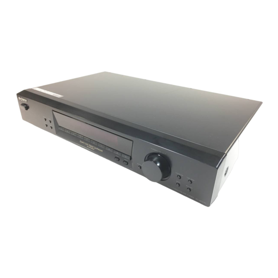
ST-SE570
General
Power requirements
Power consumption
Dimensions
Weight
Supplied accessories
Audio cord (1)
AM loop antenna (1)
FM wire antenna (1)
EON connecting cord (1)
Design and specifications are subject to change
without notice.
FM STEREO FM-AM TUNER
AEP Model
UK Model
230 V AC, 50/60 Hz
10 W
430 x 83 x 290 mm
(w/h/d)
2.5 kg
Advertisement
Table of Contents

Subscribe to Our Youtube Channel
Related Manuals for Sony ST-SE570


Summary of Contents for Sony ST-SE570
- Page 1 ST-SE570 SERVICE MANUAL AEP Model UK Model Ver 1.0 2001.04 SPECIFICATIONS FM tuner section AM tuner section General Frequency range Power requirements 230 V AC, 50/60 Hz 87.5 - 108.0 MHz Frequency range (50 kHz step) 522 - 1,611 kHz...
-
Page 2: Table Of Contents
AND IN THE PARTS LIST ARE CRITICAL TO SAFE OPERATION. REPLACE THESE COMPONENTS WITH DISASSEMBLY SONY PARTS WHOSE PART NUMBERS APPEAR AS 2-1. Disassembly Flow ............4 SHOWN IN THIS MANUAL OR IN SUPPLEMENTS PUB- 2-2. Case (407026) ..............4 LISHED BY SONY. -
Page 3: General
ST-SE570 SECTION 1 This section is extracted from instruction manual. GENERAL LOCATION OF CONTROLS – Front Panel – 2 3 4 5 AUTO BETICAL SELECT qk (7, 12) MEMORY 4 (8, 11) BAND qg (9, 10, 12) MENU 0 (9, 11, 14) CHARACTER 7 (11) Numeric buttons qf (7–9) -
Page 4: Disassembly
ST-SE570 SECTION 2 DISASSEMBLY • This set can be disassembled in the order shown below. 2-1. DISASSEMBLY FLOW 2-2. CASE (407026) (Page 4) 2-3. MAIN BOARD (Page 5) Note: Follow the disassembly procedure in the numerical order given. 2-2. CASE (407026) -
Page 5: Main Board
ST-SE570 2-3. MAIN BOARD 2 connector (CNP952) 2 connector (CNP702) 1 wire (flat type) (15 core) (CN101) 2 connector (CNP701) 4 MAIN board 3 two screws (BV/RING) -
Page 6: Test Mode
ST-SE570 SECTION 3 TEST MODE 1. Circuit Check Mode Set to the reception frequency that the circuit can STEREO RDS stations. (Set the input level to above 70 dB.) This enables circuit check to be performed in any of the reception modes-FM, AM (MW, LW). Set to a desired band before setting the test mode. - Page 7 ST-SE570 3. Entering the Factory Preset (In case perform just to write memory of the Factory Preset.) 1. Turn OFF the power. 2. While pressing 3 and AUTO-BETICAL SELECT together, turn ON POWER . 4. Forced RESET (Used to delete the contents of Factory Preset when it is written into the preset memory.) Clears all the RAMs and sets the initial state 1.
-
Page 8: Electrical Adjustments
ST-SE570 SECTION 4 ELECTRICAL ADJUSTMENTS FM Signal Level Adjustment FM RF signal generator Carrier frequency : 98 MHz Modulation : 1 kHz, 40 kHz deviation FM ANTENNA : 6.3 mV (76dB µ ) Output level 75 Ω coaxial (75 Ω open) -
Page 9: Diagrams
ST-SE570 SECTION 5 DIAGRAMS 5-1. NOTE FOR PRINTED WIRING BOARDS AND SCHEMATIC DIAGRAMS • Circuit Boards Location (In addition to this, the necessary note is printed in each block) Note on Printed Wiring Board: Note on Schematic Diagram: TRANSFORMER board •... -
Page 10: Printed Wiring Boards - Main Section
ST-SE570 5-2. PRINTED WIRING BOARDS – MAIN Section – • See page 9 for Circuit Boards Location. (Page 12) (Page 12) AC SW BOARD DISPLAY BOARD DISPLAY BOARD CN701 CN702 MAIN BOARD POWER (11) 1-681-061- TRANSFORMER BOARD PC901 AC IN... -
Page 11: Schematic Diagram - Main Section
ST-SE570 5-3. SCHEMATIC DIAGRAM – MAIN Section – • • See page 9 for Waveform. See page 14 for IC Block Diagram. C307 C305 R309 R315 L351 100p 10µH R307 C202 C203 R319 R320 4.7k 0.01 0.01 TB101 C201 R201... -
Page 12: Printed Wiring Boards - Display Section
ST-SE570 5-4. PRINTED WIRING BOARDS – DISPLAY Section – • See page 9 for Circuit Boards Location. (Page 10) (Page 10) MAIN BOARD MAIN BOARD DISPLAY BOARD CNP702 CNP701 FLUORESCENT INDICATOR TUBE NEWS/INFO 62 61 DISPLAY MEMORY ENTER DIRECT SHIFT... -
Page 13: Schematic Diagram - Display Section
ST-SE570 5-5. SCHEMATIC DIAGRAM – DISPLAY Section – • • See page 9 for Waveform. See page 14 for IC Pin Function Description. FL701 FLUORESCENT INDICATOR TUBE CN702 R732 R731 RDS-D R730 R729 MUTE R728 (Page 11) R727 CN701 R726... -
Page 14: Ic Pin Function Description
ST-SE570 • IC Block Diagrams 5-6. IC PIN FUNCTION DESCRIPTION – MAIN Board – • DISPLAY BOARD IC701 (µPD780205GF-040-3BA) IC201 LA1235 Pin No. Pin Name Description IC901 LA5667 — Power supply terminal (+5V) — Not used (open) MUTING — Not used (open) - Page 15 ST-SE570 41, 42 IS5, IS4 Setting terminal for the model 43 to 45 IS3, IS2, IS1 Setting terminal for the destination — Power supply terminal (+5V) 47 to 78 P1 to P32 Segment drive signal output to the fluorescent indicator tube (FL701) VLOAD —...
-
Page 16: Exploded Views
ST-SE570 SECTION 6 EXPLODED VIEWS NOTE: • -XX and -X mean standardized parts, so they • Items marked “*” are not stocked since they The components identified by mark 0 or dotted line with mark may have some difference from the original are seldom required for routine service. -
Page 17: Front Panel Section
ST-SE570 6-2. FRONT PANEL SECTION supplied with RV701 Ref. No. Part No. Description Remark Ref. No. Part No. Description Remark 4-997-882-51 KNOB (T) 4-951-620-01 SCREW (2.6X8), +BVTP X-4953-636-1 PANEL ASSY, FRONT A-4476-422-A DISPLAY BOARD, COMPLETE 4-231-973-01 BUTTON (POWER) 1-681-059-11 ENCORDER BOARD... -
Page 18: Chassis Section
ST-SE570 6-3. CHASSIS SECTION PT901 TB101 The components identified by mark 0 or dotted line with mark 0 are critical for safety. Replace only with part number specified. Ref. No. Part No. Description Remark Ref. No. Part No. Description Remark... -
Page 19: Electrical Parts List
ST-SE570 SECTION 7 ELECTRICAL PARTS LIST AC SW DISPLAY NOTE: • Due to standardization, replacements in the • Items marked “*” are not stocked since they The components identified by mark 0 or dotted line with mark parts list may be different from the parts speci- are seldom required for routine service. - Page 20 ST-SE570 DISPLAY ENCODER MAIN Ref. No. Part No. Description Remark Ref. No. Part No. Description Remark C104 1-126-964-11 ELECT 10uF R760 1-249-416-11 CARBON 1/4W C201 1-162-288-31 CERAMIC 330PF R761 1-249-418-11 CARBON 1.2K 1/4W R762 1-249-421-11 CARBON 2.2K 1/4W C202 1-127-876-11 CERAMIC 0.01uF...
- Page 21 ST-SE570 MAIN TRANSFORMER Ref. No. Part No. Description Remark Ref. No. Part No. Description Remark D904 8-719-024-99 DIODE 11ES2-NTA2B R902 1-249-437-11 CARBON 1/4W R903 1-249-441-11 CARBON 100K 1/4W D905 8-759-983-75 DIODE MTZJ-T-72-27 R904 1-249-437-11 CARBON 1/4W D906 8-719-947-27 DIODE MTZJ-T-72-6.8...
- Page 22 ST-SE570 Ref. No. Part No. Description Remark Ref. No. Part No. Description Remark ACCESSORIES & PACKING MATERIALS ******************************* 1-501-374-11 ANTENNA, LOOP (AM) 1-501-659-41 ANTENNA (FM) 1-770-019-11 ADAPTOR, CONVERSION PLUG 3P (UK) 1-765-383-11 CORD (WITH CONNECTOR) (EON CONNECTING CORD) 1-776-263-11 CORD, CONNECTION (AUDIO CORD)
- Page 23 ST-SE570 MEMO...
- Page 24 ST-SE570 REVISION HISTORY Clicking the version allows you to jump to the revised page. Also, clicking the version at the upper right on the revised page allows you to jump to the next revised page. Ver. Date Description of Revision...
Need help?
Do you have a question about the ST-SE570 and is the answer not in the manual?
Questions and answers