
Related Manuals for PR 5714

Summary of Contents for PR 5714
- Page 1 5 7 1 4 P r o g r a m m a b l e L E D I n d i c a t o r N o . 5 7 1 4 V 1 0 3 - U K F r o m s e r i a l n u m b e r : 1 2 1 4 9 6 0 0 1 ( A + B ) 1 3 1 0 7 7 0 0 1 ( C + D )
- Page 2 PR electronics A/S tilbyder et bredt program af analoge og digitale signalbehandlingsmoduler til industriel automation. Programmet består af Isolatorer, Displays, Ex-barrierer, Temperaturtransmittere, Universaltransmittere mfl. Vi har modulerne, du kan stole på i selv barske miljøer med elektrisk støj, vibrationer og temperaturudsving, og alle produkter opfylder de strengeste internationale standarder.
-
Page 3: Table Of Contents
Safety instructions ................. Front and back layout ................Application ....................Technical characteristics ..............Mounting ....................Applications....................Order: 5714 ....................Electrical specifications................ Sensor error detection / sensor error detection outside range ......... 12 Connections ....................14 Block diagram ................... 15 Routing diagram ..................17 Scrolling help text .................. -
Page 4: Warning
The following operations should only be carried out on a discon- nected device and under ESD safe conditions: VOLTAGE Troubleshooting the device. Repair of the device must be done by PR electronics A/S only. SYMBOL IDENTIFICATION Triangle with an exclamation mark: Warning / demand. Potentially lethal situations. -
Page 5: Safety Instructions
Should there be any doubt as to the correct handling of the device, please con- tact your local distributor or, alternatively, PR electronics A/S www.prelectronics.com. Mounting and connection of the device should comply with national legislation for mounting of electric materials, i.a. - Page 6 When disconnected, the device may be cleaned with a cloth moistened with distilled water. LIABILITY: To the extent the instructions in this manual are not strictly observed, the custom er cannot advance a demand against PR electronics A/S that would other- wise exist according to the concluded sales agreement. 5714V103-UK...
-
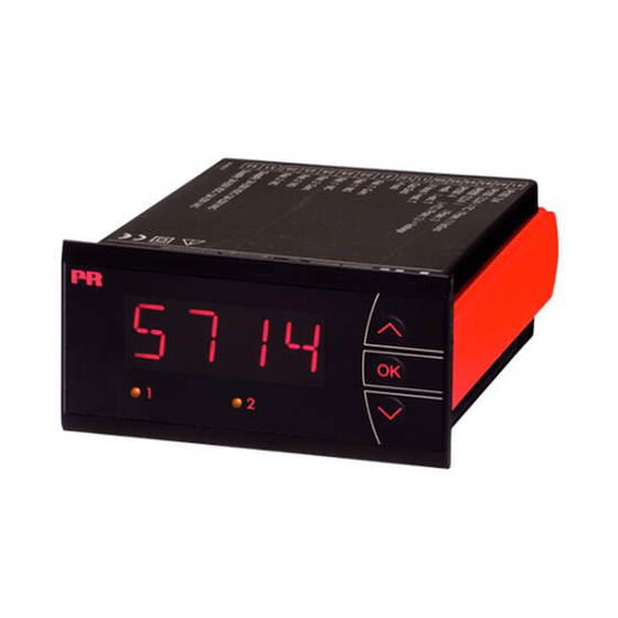
Page 7: Front And Back Layout
FRONT AND BACK LAYOUT Picture 1: Front of PReview 5714. Picture 2: Back of PReview 5714. 5714V103-UK... -
Page 8: Application
• To be mounted in front panel. The included rubber packing must be mounted between the panel cutout hole and the display front to obtain a protection degree of IP65 (type 4X). For extra protection in extreme environments, PReview 5714 can be delivered with a speially designed splash-proof cover as accessory. 5714V103-UK... -
Page 9: Applications
APPLICATIONS Input signals: Current Poten- RTD & Lin R - connection, wires tio meter Voltage Output signals: Analogue, 0/4...20 mA 2 change over relays Supply: 21.6...253 VAC 19.2...300 VDC 5714V103-UK... -
Page 10: Order: 5714
Order: 5714 Type Version 5714 Standard..... . . : A 2 relays......: B Analogue output . - Page 11 Basic values Input Basic Temperature type accuracy coefficient ≤ ±4 µA ≤ ±0.4 µA / °C Volt ≤ ±20 µV ≤ ±2 µV / °C ≤ ±0.2°C ≤ ±0.01°C / °C Pt100 Linear resistance ≤ ±0.1 Ω ≤ ±0.01 Ω / °C ≤...
- Page 12 Input for RTD types: Pt10, Pt20, Pt50, Pt100, Pt200, PT250, Pt300, Pt400, Pt500, Pt1000 Ni50, Ni100, Ni120, Ni1000, Cu10, Cu20, Cu50, Cu100 Cable resistance pr. wire, RTD (max.) ....50 Ω Sensor current, RTD ..........Nom. 0.2 mA Effect of sensor cable resistance (3- / 4-wire), RTD .............
-
Page 13: Relay Outputs
Voltage input: Measurement range ..........0...12 VDC Programmable measurement ranges ....0...1 / 0.2...1 / 0...10 / 2...10 VDC Input resistance............Nom. 10 MΩ Outputs: Display: Display readout............-1999...9999 (4 digits) Decimal point ............. Programmable Digit height ..............13.8 mm Display updating ............ -
Page 14: Sensor Error Detection / Sensor Error Detection Outside Range
Sensor error detection / sensor error detection outside range Sensor error check in 5714 variants Variant: Configuration Sensor error detection: 5714A Always: ERR1=NONE, ERR2=NONE: 5714B else: O.ERR=NONE: 5714C else: ERR1=NONE, ERR2=NONE, O.ERR=NONE: 5714D else: Outside range readout (IN.LO, IN.HI): If the valid range of the A/D converter or the polynomial is exceeded... - Page 15 Readout at hardware error Error search Readout Error cause Test of internal communication uC / ADC HW.ER Permanent error in ADC Test of internal CJC sensor CJ.ER CJC sensor defect Check-sum test of the configuration in RAM RA.ER Error in RAM Check-sum test of the configuration in EEPROM EE.ER Error in EEPROM...
-
Page 16: Connections
CONNECTIONS Inputs: RTD & Lin R, 2-wire RTD & Lin R, 3-wire RTD & Lin R, 4-wire 41 42 43 44 45 46 41 42 43 44 45 46 41 42 43 44 45 46 2-wire transmitter Current 41 42 43 44 45 46 41 42 43 44 45 46 41 42 43 44 45 46 Voltage... -
Page 17: Block Diagram
BLOCK DIAGRAM 5714V103-UK... - Page 18 Power up Fast setpoint adjustment F. S ET SETP and relay test 1 Increase setpoint REL1 -1999 2 Decrease setpoint REL2 9999 50. 0 3 Save and exit the menu /OFF 1 and 2 simultaneously = change relay state PASS DEC.
-
Page 19: Routing Diagram
ROUTING DIAGRAM If no keys are activated for 2 minutes the display returns to default state 1.0 without saving configuration changes.. 1 Increase value / choose next parameter 2 Decrease value / choose previous parameter 3 Accept the chosen parameter and go to the next menu Hold 3 Back to previous menu / return to menu 1.0 without saving REL. -
Page 20: Scrolling Help Text
SCROLLING HELP TEXT Display in default state xxxx, hardware error: REL.U SE.BR --> SENSOR WIRE BREAKAGE PERC --> SET RELAY IN PERCENTAGE SE.SH --> SENSOR SHORT CIRCUIT DISP --> SET RELAY IN DISPLAY UNITS IN.HI --> INPUT OVERRANGE IN.LO --> INPUT UNDERRANGE TYPE 9.9.9.9 -->... - Page 21 REL1 O.ERR --> ENTER RELAY 1 SETUP 23 mA --> NAMUR NE43 UPSCALE AT ERROR SKIP --> SKIP RELAY 1 SETUP 3,5 mA --> NAMUR NE43 DOWNSCALE AT ERROR --> RELAY 1 DISABLED --> DOWNSCALE AT ERROR NONE --> UNDEFINED OUTPUT AT ERROR SETP xxxx -->...
-
Page 22: Configuration / Operating The Function Keys
CONFIGURATION / OPERATING THE FUNCTION KEYS Documentation for routing diagram. In general: When configuring the display you are guided through all parameters, you can choose the settings which fit the application. For each menu there is a scrol- ling help text which is automatically shown in the display, this starts after 5 seconds if no key has been activated. -
Page 23: Graphic Depiction Of The Relay Function Setpoint
Graphic depiction of the relay function setpoint Relay units Relay units Hysteresis = 10 Setpoint = 50 Setpoint = 50 Hysteresis = 10 Off N.O. On N.O. Off N.O. Off N.O. On N.O. Off N.O. On N.C. On N.C. On N.C. On N.C. - Page 24 Displays Programmable displays with a wide selection of inputs and outputs for display of temperature, volume and weight, etc. Feature linearization, scaling, and difference measurement functions for programming via PReset software. Ex interfaces Interfaces for analog and digital signals as well as HART signals between sensors / I/P converters / frequency ®...
- Page 25 www.prelectronics.com sales-uk@prelectronics.com www.prelectronics.com sales-us@prelectronics.com www.prelectronics.cn sales-cn@prelectronics.com www.prelectronics.be sales-be@prelectronics.com Head office Denmark www.prelectronics.com PR electronics A/S sales-dk@prelectronics.com Lerbakken 10 tel. +45 86 37 26 77 DK-8410 Rønde fax +45 86 37 30 85...
Need help?
Do you have a question about the 5714 and is the answer not in the manual?
Questions and answers
How to calibrate the output coming from the oxygen analyser ro councide the reading to 20.9% and the connections ?thank you.
To calibrate the output of the PR 5714 oxygen analyzer to match a reading of 20.9%, follow these steps:
1. Use the VAL.H A.OUT xxxx parameter to set the high calibration value.
2. Enter 20.9 as the value for VAL.H to match the desired oxygen reading.
3. Ensure the output range is set appropriately using options like 0-20, 4-20, 20-0, or 20-4 mA.
4. Confirm whether to use process calibrated values by setting USE.C to YES or NO as needed.
This process adjusts the analog output so that it corresponds to 20.9% oxygen at the high calibration point.
This answer is automatically generated