
Related Manuals for PR 5715

Summary of Contents for PR 5715
- Page 1 5 7 1 5 P r o g r a m m a b l e L E D I n d i c a t o r N o . 5 7 1 5 V 1 0 2 - U K F r o m s e r i a l n u m b e r : 1 2 1 4 9 6 0 0 1 ( B ) 1 3 1 0 7 7 0 0 1 ( D )
- Page 2 PR electronics A/S tilbyder et bredt program af analoge og digitale signalbehandlingsmoduler til industriel automation. Programmet består af Isolatorer, Displays, Ex-barrierer, Temperaturtransmittere, Universaltransmittere mfl. Vi har modulerne, du kan stole på i selv barske miljøer med elektrisk støj, vibrationer og temperaturud- sving, og alle produkter opfylder de strengeste internationale stan- darder.
-
Page 3: Table Of Contents
Front and back layout ............Application ................. Technical characteristics ............ Mounting / installation ............Applications ................ Order: 5715 ................ Electrical specifications ............Sensor error detection inside and outside range....13 Connections ............... 14 Block diagram ..............15 Routing diagram ..............17 Scrolling help texts ............. -
Page 4: Warning
The following operations should only be carried out on a HAZARD disconnected module and under ESD safe conditions: Troubleshooting the module. VoLTAGE Repair of the module must be done by PR electronics A/S only. SymBoL IDENTIFIcATIoN Triangle with an exclamation mark: Warning / demand. Potentially lethal situations. -
Page 5: Safety Instructions
Should there be any doubt as to the correct handling of the module, please contact your local distributor or, alternatively, PR electronics A/S www.prelectronics.com Mounting and connection of the module should comply with national legislation for mounting of electric materials, i.e. wire cross section, protective fuse, and location. - Page 6 When disconnected, the module may be cleaned with a cloth moistened with distilled water. LIABILITy To the extent the instructions in this manual are not strictly observed, the custom er cannot advance a demand against PR electronics A/S that would otherwise exist according to the concluded sales agreement. 5715V102-UK...
-
Page 7: Declaration Of Conformity
DEcLARATIoN oF coNFoRmITy As manufacturer PR electronics A/S Lerbakken 10 DK8410 Rønde hereby declares that the following product: Type: 5715 Name: Programmable LED indicator is in conformity with the following directives and standards: The EMC Directive 2004/108/EC and later amendments EN 613261... -
Page 8: Front And Back Layout
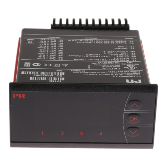
FRoNT AND BAcK LAyoUT Picure 1: Front of PReview 5715. Picture 2: Back of PReview 5715. 5715V102-UK... -
Page 9: Application
• To be mounted in panel front. The included rubber packing must be mounted between the panel cutout hole and the display front to obtain a protection degree of IP65 (type 4X). For extra protection in extreme environments, PReview 5715 can be delivered with a specially designed splash-proof cover as accessory. 5715V102-UK... -
Page 10: Applications
APPLIcATIoNS Input signals: Current RTD & Lin R - Potentio- Connection, wires meter Voltage Output signals: Analogue, 0/4...20 mA 4 change-over relays Supply: 21.6...253 VAC 19.2...300 VDC 5715V102-UK... -
Page 11: Order: 5715
5715 Type Version 5715 4 relays ....: B Analogue output and 4 relays . .: D Electrical specifications Specifications range: -20°C to +60°C... - Page 12 Basic values Input Basic Temperature type accuracy coefficient ≤ ±4 µA ≤ ±0.4 µA / °C ≤ ±20 µV ≤ ±2 µV / °C Volt ≤ ±0.2°C ≤ ±0.01°C / °C Pt100 ≤ ±0.1 Ω ≤ ±0.01 Ω / °C Linear resistance ≤...
- Page 13 Cable resistance per wire, RTD (max.) ..50 Ω Sensor current, RTD ........Nom. 0.2 mA Effect of sensor cable resistance (3- / 4-wire), RTD ......... < 0.002 Ω / Ω Sensor error detection, RTD ....... Yes Short circuit detection, RTD ......< 15 Ω Tc input: Min.
- Page 14 outputs: Display: Display readout ........... -1999...9999 (4 digits) Decimal point ..........Programmable Digit height ..........13.8 mm Display updating ......... 2.2 times / s Input outside input range is indicated by ..........Explanatory text current output: Signal range (span) ........0...20 mA Programmable signal ranges ......
-
Page 15: Sensor Error Detection Inside And Outside Range
Sensor error detection inside and outside range Sensor error check in 5715 variants: Variant: Configuration Sensor error detection: ERR1, ERR2, ERR3 and ERR4 = NONE 5715B Else: ERR1, ERR2, ERR3 and ERR4=NONE, O.ERR=NONE. 5715D Else: Outside range readout (IN.LO, IN.HI):... -
Page 16: Connections
coNNEcTIoNS Supply: 31 32 Inputs: RTD & Lin R, 2-wire RTD & Lin R, 3-wire RTD & Lin R, 4-wire 41 42 43 44 45 46 41 42 43 44 45 46 41 42 43 44 45 46 2-wire transmitter Current 41 42 43 44 45 46 41 42 43 44 45 46... -
Page 17: Block Diagram
BLocK DIAGRAm 5715V102-UK... - Page 18 Power up Fast setpoint adjustment and relay test F.SET SETP 1 Increase setpoint 2 Decrease setpoint -1999 REL1 3 Save and exit the menu 9999 REL2 50.0 /OFF REL3 1 and 2 simultaneously = REL4 relay changes state PASS DEC.P DI.LO PERC DI.HI...
-
Page 19: Routing Diagram
RoUTING DIAGRAm If no key is activated for 2 minutes, the display returns to default state 1.0 without saving configuration changes. 1 Increase value / choose next parameter 2 Decrease value / choose previous parameter 3 Accept the chosen parameter and go to the next menu Hold 3 Back to previous menu / return to default state 1.0 without saving REL.1 SETP... -
Page 20: Scrolling Help Texts
ScRoLLING HELP TExTS Display in default state xxxx, hardware error: DI.HI SE.BR --> SENSOR WIRE BREAKAGE xxxx --> DISPLAY READOUT HIGH SE.SH --> SENSOR SHORT CIRCUIT IN.HI --> INPUT OVERRANGE REL.U IN.Lo --> INPUT UNDERRANGE PERC --> SET RELAY IN PERCENTAGE 9.9.9.9 -->... - Page 21 REL1 RESP --> ENTER RELAY 1 SETUP xxx.x --> ANALOGUE OUTPUT RESPONSE TIME SKIP --> SKIP RELAY 1 SETUP IN SECONDS --> RELAY 1 DISABLED E.PAS SETP --> ENABLE PASSWORD PROTECTION xxxx --> RELAY SETPOINT AcT1 N.PAS INCR --> ACTIVATE AT INCREASING SIGNAL xxxx -->...
-
Page 22: Configuration / Operating The Function Keys
coNFIGURATIoN / oPERATING THE FUNcTIoN KEyS Documentation for the routing diagram In general: When configuring the display you are guided through all parameters, allowing you to choose the settings which fit the application. For each menu there is a scrolling help text which is automatically shown in the display if no key has been activated for appr. -
Page 23: Programming Via Pc
The customer-defined input type is saved in the 5715 in the input menu C. L IN. If the display is later configured by way of the front keys for e.g. temperature input, the input type C. - Page 24 Displays Programmable displays with a wide selection of inputs and outputs for display of temperature, volume and weight, etc. Feature linearisation, scaling, and difference measurement functions for programming via PReset software. Ex interfaces Interfaces for analogue and digital signals as well as HART signals between sensors / I/P converters / ®...
- Page 25 www.prelectronics.se sales@prelectronics.se www.prelectronics.co.uk sales@prelectronics.co.uk www.prelectronics.com sales@prelectronics.com www.prelectronics.cn sales@prelectronics.cn Head office Denmark www.prelectronics.com PR electronics A/S sales@prelectronics.dk Lerbakken 10 tel. +45 86 37 26 77 DK-8410 Rønde fax +45 86 37 30 85...
Need help?
Do you have a question about the 5715 and is the answer not in the manual?
Questions and answers