
Related Manuals for Minuteman ERide 21


Summary of Contents for Minuteman ERide 21
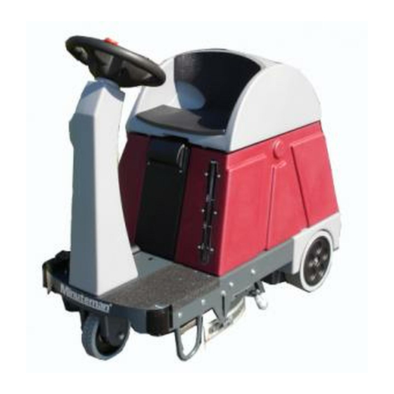
- Page 1 SERVICE MANUAL For the ERide 21 Micro Rider For: Training Troubleshooting Adjustments Rev 06/2016...
-
Page 2: Table Of Contents
TABLE OF CONTENTS CHAPTER 1 GENERAL INFORMATION 1.1 OPERATORS POSTION 1.2 LIFTING THE MACHINE 1.3 TRANSPORTING THE MACHINE 1 4 OTHER REFFERENCE MANUALS 1.4 OTHER REFFERENCE MANUALS CHAPTER 2 SAFETY 2.1 SYMBOLS USED 2.2 GENERAL INSTRUCTIONS CHAPTER 3 MACHINE DESCRIPTION 3.1 TECHNICAL CHARACTERISTICS 3.2 DESCRIPTION CHAPTER 4 SCHEDULED MAINTENANCE... - Page 3 CONTENTS CONTINUED 7.2 REMOVING BRUSH HEAD 7.3 BRUSH MOTOR TEST 7 4 BRUSH MOTOR CARBON BRUSHES 7.4 BRUSH MOTOR CARBON BRUSHES 7.5 BRUSH DRIVE BELT 7.6 BRUSH ACTUATOR 7.7 TROUBLE SHOOTING CHAPTER 8 RECOVERY SYSTEM 8.1 CLEANING THE RECOVERY WATER TANK AND GRATES 8.2 CHECK AMPERAGE OF THE VACUUM MOTOR 8.3 CHECK AND REPLACEMENT OF SUCTION MOTOR CARBONS 8.4 DISASSEMBLY/ASSEMBLY OF THE SUCTION MOTOR...
- Page 4 CONTENTS CONTINUED 10.7 DISASSEMBLY/ASSEMBLY RECOVERY WATER DRAIN HOSE CHAPTER 11 ELECTRICAL SYSTEM 11.1 BATTERY CHARGING 11.2 BATTERY DISASSEMBLY/ASSEMBLY 11.3 ADJUSTING THE MACHINE FOR DIFFERENT BATTERY TYPES 11.4 CHECKING / REPLACING FUSES 11.5 DISASSEMBLY/ASSEMBLY DRIVE ELECTRONIC BOARD 11.6 DISASSEMBLY/ASSEMBLY FUNCTIONS ELECTRONIC BOARD 11.7 REPLACING THE KEY SWITCH 11 8...
-
Page 5: Operators Postion
CHAPTER 1 OPERATOR POSITION All references to forward, back, front, rear, right, left indicated in this manual shall be deemed to refer to the operator in the driving position on the seat shall be deemed to refer to the operator in the driving position on the seat (12, Figure 3-4) LIFTING THE MACHINE WARNING! -
Page 6: Chapter 2 Safety
CHAPTER 2 SAFETY The following symbols are used to indicate potential hazardous conditions. Always read this information with attention and take any precautions necessary to protect the people and things. SYMBOLS USED DANGER! Indicates a danger with risk, even deadly, for the user. - Page 7 WARNING! •Before performing any maintenance/repair, carefully read all the instructions relevant to the maintenance / repair. •Do not use the machine for purposes other than those listed in this manual. Only use accessories recommended by the manufacturer. •Always protect the machine from sun, rain and other weather conditions, both when on and off.
- Page 8 WARNING! •The storage temperature of the machine must be between 0°C and +40 °C •The storage temperature of the machine must be between 0 C and +40 C. (32° to 104° Fahrenheit). • The humidity must be between 30% and 95%. •Do not tamper with the protections in place for the machine, for any reason.
- Page 9 •If replacing parts, ask a Dealer or Authorized Minuteman dealer for ORIGINAL spare parts. •In conditions of use comply with correct use; the vibrations will not cause dangerous situations.
- Page 10 Description Disk Brush Cyl. Deck Voltage 24 V 24 V Washed track 53 cm 51 cm Vacuum 1168 mm H2O 1168 mm H2O Tank for the detergent solution (or washing water), capacity 55 L/14.5 Gal. 55 L/14.5 Gal Water recovery tank, capacity 55 L/14.5 Gal.
-
Page 11: Description
DESCRIPTION Control panel and controls Control panel and controls (See Figure 3-1) Control panel and controls Emergency stop button Display: indicating: 3a. "READY": machine ready, or "SIT DOWN": sit on seat 3b Total hours of work done 3b. Total hours of work done 3c. - Page 13 External views • (See Figure 3-2 and Figure 3-3) • Steering wheel • Ignition key: 0: off I: on • Start pedal and acceleration • Level indicator of the detergent solution (or washing water) • Front Wheel, traction and steering g •...
- Page 14 Figure 3-2...
- Page 18 CHAPTER 5 5. CLEANING SOLUTION SUPPLY SYSTEM The significant maintenance/replacement procedures relating to the detergent solution (or washing water) supply system are described in this chapter. In addition Troubleshooting is described in the final section. 5.1 TANK CLEANING AND DETERGENT SOLUTION (OR WASHING WATER) SYSTEM Operating as described in the User and Maintenance Manual, drain the detergent solution (or washing water) tank.
- Page 20 DISASSEMBLY/ASSEMBLY DETERGENT SOLUTION (OR WASHING WATER) SUPPLY SYSTEM FILTER UNIT Removal If available, place the machine on a lifting platform, then lift. Otherwise, place the machine on a level floor. Operating on the machine's controls as provided for in the User and Maintenance Manual, lower the squeegee and the disc brush, then turn the ignition key to “0“...
-
Page 21: Removal/Installation Solution Pump
5.4 REMOVAL/INSTALLATION OF THE SOLUTION PUMP Removal If available, place the machine on a lifting platform, then lift. Otherwise, place the machine on a level floor. Operating on the machine's controls as provided for in the User and Maintenance Manual, lower the squeegee and the disc brush (or cylindrical brushes) then turn the ignition key to "0"... - Page 23 5.5 CLEANING NOZZLE AND FILTER FOR DISPENSING CLEANING SOLUTION TO DISC BRUSH Remove the brush (For the Remove the brush (For the procedure, see the User and Maintenance Manual). If available, place the machine on a lifting platform, then lift. Otherwise place the machine on Otherwise, place the machine on a level floor.
- Page 24 5.6 CLEANING THE SPRAY NOZZLE AND FILTER ON CYLINDRICAL BRUSH DECKS If available, place the machine on a lifting platform, then lift. Otherwise, place the machine on a level floor. Operating on the machine's controls as provided for in the User and Maintenance Manual, lower the cylindrical brush deck, then turn the ignition key to “0"...
-
Page 25: Troubleshooting
TROUBLESHOOTING REDUCED OR NO CLEANING SOLUTION REACHING THE BRUSH(S) REDUCED OR NO CLEANING SOLUTION REACHING THE BRUSH(S) Possible causes can be Filters for he detergent solution clogged/dirty (clean the filters) Solution valve turned off. (open the valve) Pump broken or electrical connection interrupted (replace the pump/restore the electrical connection) Debris in the detergent solution/water tank that is obstructing the exit hole (clean the tank) - Page 27 6.2 DISASSEMBLY/ASSEMBLY CHEMICAL PUMP AND ONE-WAY VALVE 1 1 . Make sure that the machine cannot move independently, and then turn the ignition key to “0“ (off) and remove the key. 2. Remove the detergent tank from the machine (1, Figure 6-2), by gripping its handle (2) and lifting.
- Page 29 TROUBLESHOOTING LITTLE OR NO DETERGENT MIXING WITH THE CLEANING SOLUTION CLEANING SOLUTION Possible causes can be: Percentage of detergent set too low (check/change the percentage by operating as described in the User and Maintenance Manual) ib d i th U d M i t Detergent tank valve dirty (clean it) Pump broken or electrical connection interrupted (replace the pump/restore...
-
Page 30: Brush System
CHAPTER 7 BRUSH SYSTEM •The significant maintenance/replacement procedures relating to the Brush system are described in this chapter. •In addition troubleshooting is described in the final section. 7.1 CLEANING DISC BRUSHES CAUTION! The use of work gloves is recommended when cleaning the disc brush, due to the possible presence of sharp debris. -
Page 31: Cleaning The Cylindrical Brushes
7.1 CLEANING THE CYLINDRICAL BRUSHES CAUTION! The use of work gloves is recommended when cleaning the cylindrical brushes, due to the possible presence of sharp debris. 1. Remove the cylindrical brushes (See the procedure in the User and Maintenance Manual). 2. -
Page 32: Brush Head
7.2 DISASSEMBLY/ASSEMBLY OF THE DISC BRUSH HEAD Removal Remove the brush (For the procedure, see the User and Maintenance th b h (F th U d M i t Manual). If available, place the machine on a lifting platform, then lift it. Otherwise, place the machine on a level floor. -
Page 33: Brush Motor Test
7.3 DISK BRUSH MOTOR TEST WARNING! This procedure must be performed by qualified personnel. Remove the disc brush (1, Figure 7-6), operating as indicated in the User and Maintenance Manual. Turn the ignition key to "0". Place a wooden block (2, Figure 7-6) 6-7 cm high under the rear wheels of the machine. -
Page 35: Brush Drive Belt
7.4 CHECK AND REPLACEMENT OF DISC BRUSH MOTOR CARBONS Removal 1. Remove the disc brush, operating as provided for in the User and Maintenance Manual). 2. Remove the disc brush holder head (See procedure in the specific paragraph). 3. Remove the disc brush drive belt (See the procedure in the specific paragraph). - Page 36 7.4 CHECK AND REPLACEMENT OF THE CARBON BRUSHES FOR THE DISK BRUSH MOTOR 1. Remove the disc brush holder head (see procedure in the specific paragraph). paragraph). 2. Externally cleaning the motor or dirt and dust, in the area of the carbon supports (1, Figure 7-7).
- Page 37 7.5 DISASSEMBLY/ASSEMBLY DISC BRUSH DRIVE BELT Removal Remove the disc brush (See the procedure in the User and Maintenance Manual) Manual). Remove the disc brush holder head (See procedure in the specific paragraph). Operating on the disc brush holder head, manually rotate the brush holder hub (1, Figure 7-8) progressively the lifting belt (2) until it disengages from the pulleys (3) and (4) and from the brush holder hub (1).
- Page 38 DISASSEMBLY/ASSEMBLY DISC BRUSH LIFT ACTUATOR Disassembly Remove the disc brush (7, Figure 3-2), operating as indicated in the User and Maintenance Manual. If available, place the machine on a lifting platform; otherwise, place the If available, place the machine on a lifting platform; otherwise, place the machine on a level floor.
-
Page 40: Troubleshooting
TROUBLESHOOTING THE BRUSH DOES NOT ROTATE Possible causes can be: Large debris or cords around the brush or between the brush and its attachment flange (remove the brush and remove debris or cords) Blown fuse for motor (replace/check for cause of overload) Electric motor with the worn carbons (replace the electric motor carbons) Faulty brush relay (replace if defective) Electric motor in the event of a failure (repair or replace the electric motor) -
Page 41: Chapter 8 Recovery System
CHAPTER 8 RECOVERY SYSTEM Maintenance/replacement procedures relating to the water recovery system are described in this chapter In addition Troubleshooting is system are described in this chapter. In addition Troubleshooting is described in the final section. CLEANING THE RECOVERY WATER TANK AND GRATES 1. - Page 43 8.2 CHECKING THE AMPERAGE OF THE VACUUM MOTOR WARNING! This procedure must be performed by qualified personnel. 1. Install a new vacuum filter on the machine (see procedure in specific paragraph). 2. Disconnect the vacuum hose from the squeegee's attachment (10, Figure 8-6). t th t (10 Fi 8 6)
- Page 44 8.3 CHECKING AND REPLACEMENT OF VACUUM MOTOR CARBON BRUSHES Remove the vacuum motor (See the procedure in the specific paragraph). Remove the cover (1, Figure 8-3) from the vacuum motor (2), by disengaging the inner retainers. Unscrew the screws (3). Disconnect the electrical connections (4).
-
Page 45: Disassembly/Assembly Of The Suction Motor
DISASSEMBLY/ASSEMBLY OF THE SUCTION MOTOR Removal Removal 1. If available, place the machine on a lifting platform; otherwise, place the machine on a level floor. Make sure that the machine cannot move independently. 2. Operating on the machine's controls as provided for in the User and Maintenance Manual, lower the brush and the squeegee, then turn the ignition key to "0"... -
Page 47: Cleaning/Check Of The Squeegee And Possible
CLEANING/CHECK THE SQUEEGEE AND REPLACEMENT OF THE SQUEEGEE BLADES Cleaning CAUTION! The use of work gloves is recommended when cleaning the squeegee, due to the possible presence of sharp debris. Remove the squeegee (See the procedure in the specific paragraph). Wash and clean the squeegee(1, Figure 8-5);... - Page 48 Inspection and Replacement of Squeegee Blades Cont. 4. Remove and clean the squeegee, operating as described above. 5. Check that the front blade (1, Figure 8-6) and the rear blade (2) are undamaged and have no cuts or tears, otherwise replace them, as described on the following page.
- Page 50 8.5 Squeegee Height Adjustment Note: Adjusting the height of the squeegee is required when the Note: Adjusting the height of the squeegee is required when the machine does not dry properly, leaving streaks of water in the central region, or on the ends. 8.
-
Page 51: Disassembly/Assembly And Cleaning/Replacing The Suction Filter
DISASSEMBLY/ASSEMBLY AND CLEANING/REPLACING THE SUCTION FILTER Removal 1. Remove the vacuum motor (See the procedure in the specific paragraph). 2. Remove the vacuum filter (1, Figure 8-8) by detaching it from the other parts of the unit the other parts of the unit. 3. - Page 52 8.7 DISASSEMBLY/ASSEMBLY - SQUEEGEE ACTUATOR Removal 1. If available, place the machine on a lifting platform; otherwise, place the machine on a level floor. Make sure that the machine cannot move independently. 2. Operating on the machine's controls as provided for in the User and Maintenance Manual, lower the squeegee, then turn the ignition key to "0"...
-
Page 53: Troubleshooting
8.8 TROUBLE SHOOTING THE ELECTRIC SUCTION MOTOR DOES NOT TURN ON THE ELECTRIC SUCTION MOTOR DOES NOT TURN ON Possible causes can be: Electric vacuum motor with worn carbons (replace the electric motor carbons) Electric vacuum motor failure (check the motor's absorption) Electronic board functions damaged (replace it) Recovery water tank, full and float activated (empty the recovery water tank) -
Page 54: Chapter 9 Drive System
CHAPTER 9 DRIVE SYSTEM The significant maintenance/replacement procedures relating to the Drive system are described in this chapter. In addition Troubleshooting is described in the final section. 9.1 PROCEDURE TO CHANGE THE MAXIMUM DRIVE SPEED OF THE 9.1 PROCEDURE TO CHANGE THE MAXIMUM DRIVE SPEED OF THE MACHINE WARNING! This procedure can only be performed by the person responsible for the machine, who must adjust the maximum speed of the machine, taking... -
Page 56: Disassembly/Assembly Of The Drive Wheel
9.2 DISASSEMBLY/ASSEMBLY OF THE DRIVE WHEEL Removal If available, place the machine on a lifting platform; otherwise, place the machine on a level floor. Make sure that the machine cannot move independently. th t th Turn the ignition key to the "0" and take it out. Apply wedges (1, Figure 9-2) to both rear wheels, to securely lock the machine. -
Page 57: Disassembly/Assembly Of The Drive Chain
DISASSEMBLY/ASSEMBLY OF THE DRIVE CHAIN Removal Remove the drive wheel (See the procedure in the specific Remove the drive wheel (See the procedure in the specific paragraph). Unscrew the screw (1, Figure 9-3.) and retrieve the washers. Remove the pinion (2) and retrieve the lug (3). Retrieve the self-lubricating bearing (4). - Page 58 WARNING! This procedure must be performed by qualified personnel. 1. Turn the ignition key to the "0". th i t th "0" 2. Apply wedges (1, Figure 9-4) to both rear wheels, to securely lock the machine. 3. Apply two suitable wooden shims (2) under the front chassis of the machine, high enough to also lift the front wheel by 6-7 cm.
- Page 60 9.5 DRIVE MOTOR CARBON BRUSHES Check 1. If you need to check all four carbons, remove the drive motor (See the If you need to check all four carbons remove the drive motor (See the procedure in the specific paragraph). 2.
-
Page 61: Disassembly/Assembly Of The Drive Motor
9.6 DISASSEMBLY/ASSEMBLY OF THE DRIVE MOTOR Removal 1. Remove the drive wheel (See the procedure in the specific paragraph). 2. Remove the drive chain (See the procedure in the specific paragraph) paragraph). 3. Remove the battery holder drum and disconnect the battery connector (6,Figure 3-4) (For the procedure, see the User and Maintenance Manual). - Page 63 9.7 DISASSEMBLY AND ASSEMBLY OF DRIVE PEDAL Removal Make sure that the machine cannot move independently and then turn Make sure that the machine cannot move independently, and then turn the ignition key to " 0" and take it out. Remove the battery holder drum and disconnect the battery connector (6, Figure 3-4) (For the procedure, see the User and Maintenance Manual).
- Page 64 9.7 ADJUSTING THE DRIVE PEDAL NOTE: Perform each operation within 10 seconds of the previous operation otherwise the board will be reset and you will have to resume operations from the start. Turn on the machine. During the start-up phase simultaneously press and hold down the (-) button of the water dosage and the (+) button of the detergent dosage –...
- Page 66 9.8 SEAT SAFETY SWITCH ADJUSTMENT Functionality check 1. Turn the ignition key to "I" without sitting on the seat of the machine and check that the control panel display shows "Sit down" (2, Figure 9-8). 2. Operating as indicated in the User and Maintenance Manual, check the correct operation of forward and backward motion of the machine.
-
Page 68: Troubleshooting
9.9 TROUBLESHOOTING THE MACHINE IS MOVING SLOWLY OR NOT MOVING Possible Causes can be: 1. Large debris or cords around the drive wheel or the drive chain (remove any debris/cords) 2. Excessive slope of floor (do not use traction to go over slopes higher than that provided for) 3. -
Page 69: Chapter 10 Miscellaneous Systems
10. Miscellaneous Systems The significant maintenance/replacement procedures relating to Miscellaneous systems are described in this chapter 10.1 TIGHTENING SCREWS AND NUTS CHECK If there is recovery water and cleaning solution (or washing water) in the corresponding tanks, empty them (See the procedure on the User and Maintenance Manual). -
Page 70: Disassembly/Assembly Control Panel Keyboard
10.2 DISASSEMBLY/ASSEMBLY CONTROL PANEL KEYBOARD Removal If available, place the machine on a lifting platform, otherwise, place the machine on a level floor. Make sure that the machine cannot move independently. Turn the ignition key to the "0" and take it out. Remove the battery holder drum and disconnect the battery connector (6, Figure 3-4) (For the procedure, see the User and Maintenance Manual. -
Page 72: Steering Wheel Disassembly/Assembly
10.3 STEERING WHEEL DISASSEMBLY/ASSEMBLY Removal Remove the electronic functions (see the procedure in the specific paragraph) but without separating the function board (1 Figure 10 3) from paragraph), but without separating the function board (1, Figure 10-3) from the support with the keyboard. Operating on the steering wheel, disconnect the electrical cables (3) from the electrical connector (4) of the emergency stop switch. -
Page 73: Steering Column Disassembly/Assembly
10.4 STEERING COLUMN DISASSEMBLY/ASSEMBLY Removal 1 Remove the steering wheel (See the procedure in the specific paragraph) 1. Remove the steering wheel (See the procedure in the specific paragraph). 2. Unscrew the screws (1, Figure 10-4) and gently lift the steering column (2). 3. - Page 74 10.5 DISASSEMBLY/ASSEMBLY OF THE CLEAN WATER SIGHT GAUGE REMOVAL Empty the detergent solution tank (or washing water) (See the procedure in the User and Maintenance Manual). Make sure that the machine cannot move independently, and then turn the ignition key to " 0" and take it out. WARNING Wear gloves and protective clothing suitable for the task.
- Page 75 10.6 DISASSEMBLY/ASSEMBLY OF DRAIN HOSE FOR THE CLEAN WATER TANK Removal Empty the detergent solution tank (or washing water) (See the procedure in the User and Maintenance Manual). If available, place the machine on a lifting platform; otherwise, place the machine on a level floor. Make sure that the machine cannot move independently.
-
Page 76: Disassembly/Assembly Recovery Water Drain Hose
10.7 DISASSEMBLY/ASSEMBLY RECOVERY WATER DRAIN HOSE Removal 1. Empty the recovery water tank (see the procedure in the User and Maintenance Manual). 2. If available, place the machine on a lifting platform, and raise it up; otherwise, place the machine on a level floor. Make sure that the machine cannot move independently. -
Page 77: Chapter 11 Electrical System
11. ELECTRICAL SYSTEM The significant maintenance/replacement procedures relating to The significant maintenance/replacement procedures relating to the Electrical system are described in this chapter. Troubleshooting and arrangement of the components of the electrical system is also described; the Wiring Diagram has also been inserted. - Page 78 11.2 Battery Wiring 11. 3 Adjusting the machine for the type of batteries installed Caution! In the context of the procedure described on the next page In the context of the procedure described on the next page, concerning the "adjustment of the machine for the type of batteries installed", make sure you do not vary any other setting of the machine.
- Page 79 11.3 Battery Charger settings NOTE: Perform each operation within 10 seconds of the previous operation otherwise the board will be reset and you will have to resume operations from the start. 1. Turn the machine on. 2. During the start-up simultaneously press and hold down the ( ) button of the water dosage and the (+) button of the the (-) button of the water dosage and the (+) button of the detergent dosage - the display shows "USER CHECK -...
-
Page 80: Checking/Replacing Fuses
11.4 CHECKING/REPLACING FUSES . Make sure that the machine cannot move independently. 2 Turn the ignition key to the "0" and take it out 2. Turn the ignition key to the 0 and take it out. 3. Remove the battery holder drum and disconnect the battery connector (6, Figure 3-4) (See the procedure in the User and Maintenance Manual). - Page 81 11.4 Fuses...
-
Page 82: Disassembly/Assembly Drive Electronic Board
11.5 DISASSEMBLY/ASSEMBLY DRIVE ELECTRONIC BOARD Remove Remove the battery holder drum and disconnect the battery connector (6, Figure 3-4) (For the procedure, see the User and Maintenance Manual). Open the cover (1, Figure 11-3) and remove the panel (2) by lifting it up. -
Page 83: Disassembly/Assembly Functions Electronic Board
11.6 DISASSEMBLY/ASSEMBLY FUNCTIONS ELECTRONIC BOARD Removal 1. If available, place the machine on a lifting platform, otherwise, place il bl lifti l tf the machine on a level floor. Make sure that the machine cannot move independently. Turn the ignition key to the "0" and take it out. 3. - Page 85 11.7 KEY SWITCH INSTALLATION Removal Remove the steering column (See the procedure in the specific paragraph). Operating from inside the steering column (1, Figure 11-5), loosen the lock nut (2) and remove the ignition key (3). Assembly Assembly Assemble, by reversing the sequence of operations performed for disassembly...
-
Page 86: Troubleshooting
11.8 TROUBLE SHOOTING See the other chapters, as already indicated for other systems that use the electrical system electrical system. Also other possible causes of failure can be: Flat batteries or their connections not efficient (charge battery or clean the connections) Broken batteries (check flat battery voltage) B tt... - Page 87 11.9 ALARM CODES...
-
Page 88: Wiring Diagram
11.10 WIRING DIAGRAM 7CH4Q90A: Drive board 7CFI0000: Functions board CA: Battery charger FE: Emergency stop button FE: Emergency stop button RC: Battery charger relay SW2: Water float TX2: Drive board TX serial connection RX2: Drive board RX serial connection RX1 : Battery charger RX serial connection K1: Brush contactor K2: Vacuum contactor K3: Brush release contactor... -
Page 90: Relays
12. Relays and Drive Controller... -
Page 91: Notes
13. Notes...
Need help?
Do you have a question about the ERide 21 and is the answer not in the manual?
Questions and answers