
Subscribe to Our Youtube Channel
Related Manuals for LSI GS320


Summary of Contents for LSI GS320
- Page 1 GS320 Display & Wind Speed Sensor Installer and User’s Manual ENGLISH GM320_ENG_rev20150223_v1.3...
-
Page 2: Table Of Contents
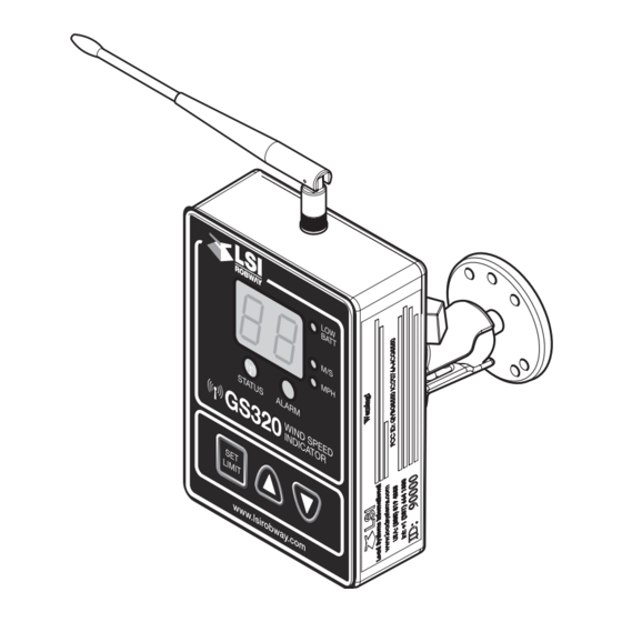
THE GS320 SYSTEM TABLE OF CONTENTS LIST OF FIGURES 1: GENERAL ..............3 Figure 1: GS320 Display ..........4 1.1 Introduction ............3 Figure 2: Example of ID number 18820 ......4 1.2 Recommended Operating Conditions .....3 Figure 3: Remove sensor box from mounting plate ..5 1.3 Start-Up ............3... -
Page 3: 1: General
1.4 About This Manual The wind speed indicator kit includes a GS320 display WARNING and a wind speed sensor. The GS320 creates a two-way radio network with the wind speed sensor to bring live ReaD CaRefUllY anD UnDeRsTanD THIs readings on screen. The GS320 has a user-adjustable ManUal befoRe PRoCeeDIng. -
Page 4: 2: Operation
Down button to save the ID number and above options and then exit. When the GS320 is started, it wakes up the wind speed sensor programmed to it and takes control of the sensor. “CA” means Cancel. Press the Down button This means that if a second display is programmed to exit without saving. -
Page 5: 3: Maintenance
THE GS320 SYSTEM 3: MAINTENANCE 3.1 Replacing the Sensor Battery New high quality “D” cell battery: 3.6 V lithium, or “D” 1.5 V alkaline CAUTION PRoTeCT THe InTeRIoR of THe sensoR fRoM DIRT anD HUMIDITY aT all TIMes. NOTE boTH lITHIUM oR alKalIne baTTeRIes Can be UseD;... -
Page 6: Replacing The Sensor Antenna
THE GS320 SYSTEM 3.2 Replacing the Sensor Antenna 7. Slide the white nylon hex bolt to the middle of the length of the new antenna. Heavily damaged antennas (ripped out, sheared off, wire 8. Coat the exposed metal foot of the new antenna exposed and fraying etc.) should be replaced to ensure... -
Page 7: 4: Installation
INSTRUCTIONS AND USING LSI-ROBWAY To ensure reliable radio communication between wind SUPPLIED COMPONENTS ONLY. speed sensor and the GS320, the antenna should faIlURe To InsTall all PaRTs, oR RePlaCIng PaRTs oR CoMPonenTs WITH not be in contact with metal and should have a direct PaRTs oR CoMPonenTs noT sUPPlIeD and clear line of sight to the sensor antenna. -
Page 8: Power Supply Verification
The power from the crane needs to be checked in the rated at least three amperes, that supplies +12 or DC and AC modes under the following conditions: +24 volts when the machine is in use. The GS320 will • Engine start-up automatically detect the voltage level and adjust itself. -
Page 9: Wireless Wind Speed Sensor Gs020
THE GS320 SYSTEM 4.3 Wireless Wind Speed Sensor GS020 d. There should be a clear and unobstructed line of sight between the wind speed sensor antenna and 1. Remove the mounting rod from the wind speed the cabin mounted display unit. -
Page 10: 5: Certification Notes
THE GS320 SYSTEM 5: CERTIFICATION NOTES 5.1 FCC and IC—Instructions to the User To reduce potential radio interference to other users, the antenna type and its gain should be so chosen that This equipment has been tested and found to comply the equivalent isotropically radiated power (e.i.r.p.) is not... - Page 11 THE GS320 SYSTEM 5.2 CE 5.2a Declaration of conformity 5.2b CE Safety WARNING CAUTION WHen sensoRs aRe UseD, THe aMbIenT THe IP of eQUIPMenT CoRResPonDs To 65. TeMPeRaTURe sHoUlD noT be HIgHeR THan 84ºC anD THe DIsPlaY sHoUlD noT be UseD WHen THe aMbIenT TeMPeRaTURe Is HIgHeR THan 59ºC,...
-
Page 12: 6: Limited Warranty - April 1
Products is 12 months after delivery of such product. Please in order to, among others, ensure that the written instructions consult LSI for any Product that is not listed in the above chart and applicable standards, including safety margins, were for further details. -
Page 13: Exclusion
Product user’s control, including war, riot, strikes, by LSI in Ontario and anywhere else in Canada; and embargoes) or external cause; - the laws of the State of New York for products sold by LSI • Any cost, damage or expenses for field labor or... -
Page 14: Notes
THE GS320 SYSTEM NOTES SkyAzúl, Equipment Solutions www.skyazul.com... -
Page 15: Revision History
REVISION HISTORY Version Date Summary of Change Approved By May 21, 2013 Updated formatting to LSI-Robway style. B. Pimparé July 30, 2013 Minor formatting and wording changes for internal consistency. M. Young Feb. 23, 2015 Logo & address updates, etc.
Need help?
Do you have a question about the GS320 and is the answer not in the manual?
Questions and answers