
Related Manuals for InHand InRouter 700 Series


Summary of Contents for InHand InRouter 700 Series
- Page 1 InRouter 700 Series User’s Manual © 2016 InHand Networks, All rights reserved. Republication without permission is prohibited.
- Page 2 Disclaimer Information in this document is subject to change without notice and does not represent an obligation on the part of InHand Networks. This user manual may include intentional technical or typographical errors. Changes are periodically made to the manual to correct such errors, and these changes are not informed in new editions.
-
Page 3: Table Of Contents
Introduction to InRouter 700 Series ............................2 Overview ................................2 Package Checklist ..............................5 Product Features ..............................6 1.3.1 Interfaces ................................6 1.3.2 Functions ................................7 1.3.3 Environmental Limits ............................8 1.3.4 Power Requirements ............................8 1.3.5 Physical Characteristics ............................. 8 1.3.6 Advanced Industrial Features .......................... -
Page 4: Introduction To Inrouter 700 Series
Introduction to InRouter 700 Series Overview ◆ Product Models ◆ Product Features & Specifications ◆ Package Checklist ◆ 1.1 Overview... - Page 5 InRouter 700 series industrial grade routers provide users with stable and high speed connection between remote devices and customer’s center via 2.5G/3G networks. They allow wide voltage power supply (9-48V DC), large range operating temperature from -25° C to 70° C (-10 ~ 158F)/ humidity: 95% RH, and fully satisfy various EMC verifications, which ensure stability and reliability under harsh industrial conditions.
-
Page 6: Important Safety Information
Important Safety Information This product is not intended for use in the following circumstances Area(s) where radio transmission equipment (such as cell phone) are not permitted. Hospitals, health care facilities and area(s) where cell phones are restricted by law. ... -
Page 7: Package Checklist
We put each InRouter 700 cellular router in a box with standard accessories. Additionally, there’re optional accessories can be ordered. When you receive our package, please check carefully, and if there’re items missing or appearing to be damaged, please contact with your InHand Networks sales representative. Items in package include:... -
Page 8: Product Features
1.3 Product Features 1.3.1 Interfaces Cellular WAN: Band Options: HSPA+/HSPA/UMTS 850/900/1900/2100MHz GSM/GPRS/EDGE 850/900/1800/1900MHz Ethernet WAN: Ethernet: 10/100 Mbps, RJ45 connector, Auto MDI/MDIX Magnetic Isolation Protection: 1.5 KV built-in IR701/791: Number of Ports: 1 Ethernet: 10/100 Mbps, RJ45 connector, Auto MDI/MDIX Magnetic Isolation Protection: 1.5 KV built-in IR704/794: Number of Ports: 4... -
Page 9: Functions
1.3.2 Functions Support VPDN/APN, fast access to virtual private dial-up network (VPDN) provided by mobile operator, ensure high-security data transmission. Support PPPoE (Point to Point Protocol over Ethernet) Protocol. Support CHAP/PAP/MS-CHAP/MS-CHAP V2 authorization Support Connection Detection, auto-recovery, auto-link, ensure reliable communication. Support On-demand connection, SMS Activity Dynamic IP Support DHCP, applied as Server/Client... -
Page 10: Environmental Limits
1.3.3 Environmental Limits Operating Temperature: -25 to 70° C (-10 to 158° F) Operating Humidity: 5 to 95% RH Storage Temperature: -40 to 85° C (-40 to 167° F) 1.3.4 Power Requirements Power Inputs: 1 terminal block, including power jack and serial. Input Voltage: 12 -48 VDC 1.3.5 Physical Characteristics Housing: Steel, providing IP30 protection... -
Page 11: Device Management Software
Damped oscillation Immunity: EN61000-4-12, Level 3 Power-frequency electromagnetic fields Immunity: EN61000-4-8, Level 3 Anti-shock: IEC60068-2-27 Drop: IEC60068-2-32 Vibration: IEC60068-2-6 1.3.7 Device Management Software Device Manager: Centralized management solution for InHand Networks Devices 1.3.8 Warranty Warranty Period: 1 year (Optional service for 3 years) -
Page 12: Product Models
1.4 Product Models The current models of InRouter700 Series include: InRouter701/791GS55,InRouter701/791PH09,InRouter 704/794PH09. The models are classified according to main difference including cellular network, VPN support and interface for device. Ethernet Model Serial Cellular WAN X.509 base64 GPRS GSM/GPRS IR701GS55 RS232/485 1 RJ45 850/ 900/1800/1900 MHz GSM/GPRS... -
Page 13: Quick Installation Guide
Quick Installation Guide Typical Application ◆ Panel Layout ◆ Quick Connect to Internet ◆ Quick IPSec VPN Configuration ◆ Reset to Factory Defaults ◆... -
Page 14: Typical Application
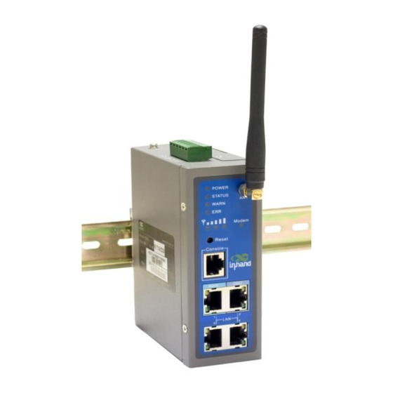
2.1 Typical Application InRouter 700 series can be used to connect your device (with RS232/485/Ethernet Interface) to internet via GPRS/HSUPA cellular network. Meanwhile, to ensure the security and access, InRouter 700 series support VPN, enabling remote access and secure data transmission through Internet. - Page 15 IR704/794: Interface Description Power Interface Access 12-48 V DC Power Supply Serial Access to the serial line, realizing One 10/100Base-TX RJ45 Port (IR701/791GS55, IR701/791PH09, IR701/791UE) Ethernet Ports Four 10/100Base-TX RJ45 Ports, (IR704/794UE, IR704/794PH09) ANTENNA 2.5G/3G antenna SIM Card Connector Hold SIM card Description of LED Legend: On-- Off--...
-
Page 16: Quick Connection To Internet
Link the power supply in the product package with InRouter, watch where the InRouter Power LED on the panel is light up. If not, please connect with InHand for technical supports. You can configure IR700 after the Power LED lights up. -
Page 17: Build Connection Between Inrouter And Your Pc
2.3.5 Build Connection between InRouter and your PC IR700 Router can auto-distribute IP address for PC. Please set the PC to automatically obtain IP address via DHCP. (Based on the Windows Operation System): 1) Open “Control Panel”, double click “Network Connections” icon, and enter “Network Connections” Screen. 2) Double click “Local Area Connection”, enter “Local Area Connection Status”... - Page 18 Click “OK”, InRouter will allocate an IP address: 192.168.2.X, and a gateway: 192.168.2.1(the default address of IR700). After configure TCP/IP protocols, you can use ping command to check whether the link between PC and Router is built correctly. Below is an example to execute Ping command under Windows XP: Ping 192.168.2.1 If the screen shows: Then the PC and InRouter are correctly connected.
-
Page 19: Start To Configure Your Inrouter 700(Optional)
2.3.6 Start to configure your InRouter 700(Optional) After you have finished the former steps, you can configure the Router: 1) Open IE browser, input the default IP address of the Router: http://192.168.2.1, you can see the login page as below: Input “username”... -
Page 20: Connect Inrouter With Internet
2.3.7 Connect InRouter with Internet Follow the configuration steps below to enable IR700 to connect to Internet. Click “Network”=>“Dialup”, enter dialup configuration interface: Please check the APN, Dialup Number, Username and Password: Dialup Number, Username and Password are provided by local mobile operator. The following examples show parameters provided by China Mobile, Vodafone. -
Page 21: Quick Ipsec Vpn Configuration
2.4 Quick IPSec VPN Configuration If you need to build a VPN tunnel to access to your remote PLC through Internet or you need to ensure security of the data transmission, here’s a quick configuration guide of IPSec for InRouter700 Series Connect PC with Router to enter router configuration interface, select “VPN”... - Page 22 Click “Add” to add a new IPSec Tunnel: Basic Parameters: basic parameters of IPSec tunnel. Tunnel Name: name IPSec tunnel, the default is IPSec_tunnel_1. Destination Address: set to VPN server IP/domain, e.g.: the domain provided by GJJ is gjj-ovdp.3322.org. Startup Modes: select Auto Activated. Negotiation Mode: optional between Main Mode and Aggressive Mode.
-
Page 23: Reset To Factory Defaults
You can click “Show Detail Status” to observe the specific connection details, or click “Add” to add a new tunnel.: Now you have successfully built a high-security IPSec tunnel. Here’s an example. We set an IPSec Tunnel from subnet: 192.168.220.0/24 to subnet: 192.168.123.0/24, when it succeeds, the screen will show: And the PC in IPSec client subnet can get access to the server’s subnet. -
Page 24: Web Approach
3) After a few seconds, the ERROR LED then turns off, now press RESET button again: 4) Then you will see ERROR and STATUS LED blink, which means reset to factory defaults succeed! Factory default settings: IP: 192.168.2.1 Net Mask: 255.255.255.0 Serial parameter: 19200-8-N-1 2.5.2 Web Approach 1) Login the web interface of IR700, select “System””Config Management”:... -
Page 25: Advanced Configuration
Advanced Configuration Configuration on Web ◆ 3.1 Configuration on Web InRouter must be correctly configured before use. This Chapter will show you how to configure InRouter via Web interfaece. 3.1.1 Preparation Firstly, connect your devices to IR700 with a cable or a HUB (switch), then set the IP of PC and IR700 in the same subnet, for example: Set PC IP to 192.168.2.50, net mask: 255.255.255.0, gateway (default IP of IR700: 192.168.2.1 ):... - Page 26 Open IE browser, input the IP address of IR700: http://192.168.2.1 (default IP of IR700). Then you’ll see the Login Window pop up, you need to login as Administrator. Input the username and password (default: adm/123456). Click “Login” to enter configure interface:...
-
Page 27: System
3.1.2 System System settings include the 9 parts: Basic Setup, Time, Serial Port, Admin Access, System Log, Config Management, Update, Reboot and Logout. (1) Basic Setup Parameters Name Description Default Example Language Choose language of configuration web Chinese English Router Name Set name of InRouter Router My InRouter... - Page 28 (2) Time Name Description Default Router Time Display router time 1970-1-1 8:00:00 PC Time Display PC time (or the time of device linked with router) Time Zone Set time zone Custom Custom TZ string Set the string of time zone of Router CST-8 Auto Update Time Time Update Interval...
- Page 29 (4) Admin Access Name Description Default Username/Password Username Username for configuration web login Old Password To change the password, you need to input the old one 123456 New Password Input new password Confirm New Password Input the new password again Management HTTP/HTTPS/TELNET/SSHD/Console Enable...
- Page 30 (5) System Log Name Description Default Log to Remote System Enable remote log server Disable IP address/Port (UDP) Set the IP and Port of remote log server Port: 514 (6) Config Management Name Description Router Configuration Import/Backup configuration file Restore default configuration Click to reset IR700 (to enable RESET, you need to reboot IR700) Network Provider (ISP) Used to configure the APN, username, password and other parameters of major operators...
-
Page 31: Network
Click “update”, and then click “sure” to begin update, the window will show as below. Upgrade firmware succeed, and click “reboot” to restart IR700. (8) Reboot If you need to reboot system, please click ”System”=>”Reboot”, Then click ”OK” to restart system. (9) Logout If you need to logout system, click “System”=>”Logout”, and then click “OK”. - Page 32 (1) Dialup Name Description Default Enable Enable PPP dialup Enable Time Schedule Set time for online and offline SHARED Enabled—device linked with Router Can access to internet. Enable Disable—device Can NOT access to internet via Router. Select local ISP, if not listed here, please select ”Customer” Customer Network Select Type Choose mobile network type...
- Page 33 “gprs” or ”CDMA” Password Dialup parameters provided by Local ISP Primary Profile Retries After retries and dialup still failed, router will try backup dialup parameters (if you (always main have set two IPSec tunnels and one as backup, router will also stop the main one and parameters and never use try another, more details please see at “VPN”...
- Page 34 Thursday Enable Friday Enable Saturday Blank Time Range 1 Set Time Range 1 9:00-12:00 Time Range 2 Set Time Range 2 14:00-18:00 Time Range 3 Set Time Range 3 0:00-0:00 Description Describe configuration Blank (2) WAN (for IR7x4 only) This page is to set the type of WAN port: Name Description Default...
- Page 35 Gateway Set WAN Gateway 192.168.1.1 Set Max Transmission Unit, optional between default and manual 1500 Multi-IP Settings(can set 8 additional IP address at the most) IP address Set the additional IP address of LAN Blank Net Mask Set Net Mask Blank Description Describe the settings...
- Page 36 SHARED Enabled—the local device linked with Router can get access to internet. Enable Disable—the local device can’t get access to internet via Router. MAC Address Set MAC Address Set Max Transmission Unit, optional between default and manual 1500 ADSL Dialup (PPPoE) Settings Username Set username for dialing up Blank...
- Page 37 Name Description Default MAC Address The MAC address in LAN 00:10:A1:86:95:02 (Provided by InHand) , for manufactures IP Address Set IP Address in LAN 192.168.2.1 (If Changed, you need to input the new address for entering the configuration web) Net Mask Set Net Mask of LAN 255.255.255.0...
- Page 38 Configure this page after select WAN-DMZ-LAN mode in Port Mode page. Name Description Default MAC Address Set MAC address of DMZ port (Provided by Manufacture: InHand) IP Address Set IP Address of DMZ port 192.168.3.1 Net Mask Set Net Mask of DMZ port 255.255.255.0 Optional between Default & Manual...
- Page 39 (8) Port Mirror (for IR7x4 only) This function is used for Engineer capture packages of different ports of IR700. Destination Port: the port to which you wand to send the copied packages. Here we set Port 3 as example, after you set Port 1 as destination port, and Port 3“Both”, you can link your PC to Port 1 and get the packages sent and received by Port 3.
- Page 40 Name Description Default Service Type DynDNS - Dynamic http://www.dyndns.com/ Username Registered username for DDNS Password Registered password for DDNS Hostname Registered hostname for DDNS (11) Static Route Name Description Default Destination Set IP address of destination Blank Net Mask Set subnet Mask of destination 255.255.255.0 Gateway Set the gateway of destination...
-
Page 41: Service
3.1.4 Service Service settings include DHCP Service, DNS Forwarding, VRRP and other related parameters. (1) DHCP Service Name Description Default Enable DHCP Click to enable DHCP Enable IP Pool Starting Address Set the starting IP address of DHCP pool 192.168.2.2 IP Pool Ending Address Set the ending IP address of DHCP pool 192.168.2.100... - Page 42 (3) DHCP Relay This function can realize DHCP relay and send relay packages to LAN interface of router. Name Description Default Enable DHCP Relay Click to enable DHCP Relay Enable (after enable DHCP) DHCP Server Set the DHCP Server’s address, always you need Blank ensure DHCP server is in the same LAN or VPN subnet as IR700’s LAN...
- Page 43 (5) Device Manager Name Description Default Mode Disabled/Only SMS/SMS+IP Disable Name Description Default Mode Only SMS Query SMS Interval Set how long to check SMS 24 hours Trust Phone List Add trust Cell Phone List Name Description Default Mode SMS+IP Mode Vendor Set Vendor Name Default...
- Page 44 Query SMS Interval Set how long to check SMS Trust phone list Set trust cell phone list (6) DTU Name Description Default Enable Click to enable DTU Disable DTU Protocol Set DTU protocol, Please see more in related Quick Guide Transparent Protocol Optional between TCP/UDP...
-
Page 45: Firewall
Status Query Set Status Query SMS, and you can see status of router by send SMS (e.g.: show status). Reboot Let the router reboot SMS Access Control Default Policy Block or Accept control SMS from certain Phone Block Phone List Include phone numbers accepted or blocked to send SMS to router Notice: Before using this function, please make sure you have a SIM card in the router that has SMS function. - Page 46 (3) Port Mapping Name Description Default Enable Click Enable Port Mapping Disable Source To fill with source IP 0.0.0.0/0 Service Port Fill the port of service 8080 Internal Address Set the internal IP for mapping Blank Internal Port Set the Port mapping to internal 8080 Click to enable log about port mapping.
-
Page 47: Qos
Mapping all the ports and then external PC can get access to all the ports of internal device behind IR700. Attention: this function cannot map the admin port of IR700 (e.g.: 80 TCP) to the device’s port. Name Description Default Enable DMZ Click to Enable DMZ Disable... - Page 48 IPSec Settings Description: 1. Select to Enable or Disable NATT, normally we need to enable, unless you ensure there is no NAT routers in the network. 2.Select to enable Compression Mode or Debug Name Description Default Enable NAT Transversal Click to enable NATT Enable (NATT) Keep alive time interval of NATT...
- Page 49 Name Description Default Show Advanced Options Click to enable advanced options Disable Basic Parameters Tunnel Name To name the tunnel IPSec_tunnel_1 Destination Address Set the destination address of IPSec VPN Server Blank Startup Mode Auto Activate/Trigged by Data/Passive/Manually Activated Enable Negotiation Mode Optional: Main Mode or Main Mode...
- Page 50 Key (While choosing Shared Key Authentication Set IPSec VPN Negotiation Key Blank Type) Phase 2 Parameters IPSec Policy Optional: 3DES-MD5-96 or AES-MD5-96 3DES-MD5-96 IPSec Lifetime Set IPSec Lifetime 3600sec Perfect Forward Secrecy (PFS) Optional: Disable, GROUP1, GROUP2, GROUP5 Disable ((Enable Advanced options) Link Detection Parameters (Enable Advanced options) DPD Time Interval Set DPD Time Interval...
- Page 51 (4) L2TP Clients Name Description Default Enable Click Enable Enable Tunnel Name Set Tunnel Name L2TP_TUNNEL_1 L2TP Server SetL2TP Server Address Blank Username Set Server Username Blank Password Set Server Password Blank Server Name Set Server Name l2tpserver Startup Modes Set Startup Modes: Auto Activated, Auto Activated...
- Page 52 Set MTU parameters 1500 Set MRU parameters 1500 Enable Debug Mode Click Enable Debug Mode Blank Expert Options For InHand R&D only Blank (6) Open VPN Tunnels In the configuration WEB of 700, select “VPN”=> “Open VPN Tunnels” as below:...
- Page 53 Click “Add” to add a new Open VPN tunnel: Name Description Can’t be set Tunnel name Enable Enable this configuration Mode Client or Server Protocol UDP or TCP Port Import or Export Certificate (CRL) OPEN VPN Server’s IP or DNS OPEN VPN Server Authencation Type (1) None ----- for host to host connection (not available when 700 as server)
- Page 54 CA needed: Client: root CA (ca.crt), public key (pub.crt), private key (pri.key) Server: root CA (ca.crt), public key (pub.crt), private key (pri.key) (5) X.509 Cert -----CA mode for host to host tunnel CA needed: Client: root CA (ca.crt), public key (pub.crt), private key (pri.key) Server: root CA (ca.crt), public key (pub.crt), private key (pri.key) (6) User+X.509 mode------username + password + CA certificate CA needed: Client: root CA (ca.crt), public key (pub.crt), private key (pri.key)
-
Page 55: Tools
(8) Certificate Management Name Description Default Enable SCEP Click Enable (Simple Certificate Enrollment Protocol) Certificate Protected Key Set Certificate Protected Key Blank Certificate Protected Key Confirm Confirm Certificate Protected Key Blank Import/Export CA Certificate Import or Export (CA) Certificate Blank Import/Export Certificate (CRL) Import or Export Certificate (CRL) Blank... -
Page 56: Status
(2) Trace Route Name Description Default Host Destination for Trace Route Blank Max Hops Set Max Hops Time Out Set Time Out 3 sec Protocol Optional: ICMP/UDP Expert Options Advanced parameters Blank (3) Link Speed Test Test link speed via unload or download 3.1.9 Status Status contains System, Modem, Network Connections, Route Table, Device List and Log. - Page 57 (2) Modem Status This page shows the status of Modem, including signal level. (3) Network Connections This page shows the network connections via WAN or LAN...
- Page 58 This page shows the log of system, including download log file. Under certain situation when there’re problems that can’t be diagnosed at the moment, you’ll be asked to provide the diagnose log to InHand engineers, you may click “Download System Diagnosing Data” and then send the diagnose log to...
-
Page 59: Cli Configuration
CLI Configuration 4.1 CLI Operation Step 1: Input telnet LAN IP to login CLI configuration. For example: Step 2: After connection is succeed, input username and password of IR700. The default username/password is adm/123456 Attention: password will not be showed. Step 3: Login to User Mode... - Page 60 Step 4: enter privileged mode, password is 123456 Step 5: Login to privileged mode successfully Step 6: Enter configured mode, then you could configure parameters you want to set up.
-
Page 61: Cli Command
4.2 CLI command Configure username and password Enable serial function Configure serial port parameters, like baudrate, parity, stop bit and so on. Enable advanced options of dialup Configure ICMP server Configure LAN IP Enable DHCP function Configure DHCP IP pool: 192.168.2.10-192.168.2.20 Enable HTTP function Configure HTTP service port Enable HTTP local access... - Page 62 Enable HTTP remote access Check device ID After configuration, please don’t forget to commit and reboot router!
-
Page 63: Faq
InRouter is powered on, but can not access Internet through it? Please check: Whether the InRouter is inserted with a SIM card. Whether the SIM card is enabled with data service, whether the service of the SIM card is suspended because of an overdue charge. - Page 64 InRouter is powered on, but the Network LED is not on when connected to PC? When the PC and InRouter are connected with a network cable, please check whether a network crossover cable is used. Check if the network cable is in good condition. ...
- Page 65 Support In case you have problems with the installation and use, please address them to us by e-mail: support@inhandnetworks.com. InHand Networks 3900 Jermantown Rd., Suite 150 Fairfax, VA 22030 T: +1-703-348-2988 F:+1-703-348-2988 info@inhandnetworks.com www.inhandnetworks.com...
Need help?
Do you have a question about the InRouter 700 Series and is the answer not in the manual?
Questions and answers