
Subscribe to Our Youtube Channel
Related Manuals for Garmin Flight Stream 110/210


Summary of Contents for Garmin Flight Stream 110/210
- Page 1 Flight Stream 110/210 TSO Installation Manual 190-01700-00 October 2014 Revision B...
- Page 2 Garmin. ©2014 The Bluetooth® word mark and logos are registered trademarks owned by Bluetooth SIG, Inc. and any use of such marks by Garmin is under license. Other trademarks and trade names are those of their respective owners.
- Page 3 Section 5 5-1 through 5-1 Section 6 6-1 through 6-2 Section 7 7-1 through 7-1 Section 8 8-1 through 8-1 Appendix A A-1 through A-1 Appendix B B-1 through B-7 190-01700-00 Flight Stream 110/210 TSO Installation Manual Rev. B Page B...
- Page 4 California's Proposition 65. If you have any questions or would like additional information, please refer to our web site at www.garmin.com/prop65. WARNING Perchlorate Material – special handling may apply, visit www.dtsc.ca.gov./hazardouswaste/perchlorate. 190-01700-00 Flight Stream 110/210 TSO Installation Manual Rev. B Page i...
-
Page 5: Through
(iv) damage caused by service performed by anyone who is not an authorized service provider of Garmin; or (v) damage to a product which has been modified or altered without the written permission of Garmin. In addition, Garmin reserves the right to refuse warranty claims against products or services which are obtained and/or used in contravention of the laws of any country. -
Page 6: Table Of Contents
Flight Stream 210 ........................5-1 CONNECTOR PINOUT INFORMATION ...................6-1 Flight Stream Pin Out List ......................6-1 TROUBLESHOOTING ........................7-1 APPENDIX A OUTLINE AND INSTALLATION DRAWING ............A-1 APPENDIX B INTERCONNECT DRAWINGS ................B-1 190-01700-00 Flight Stream 110/210 TSO Installation Manual Rev. B Page iii... - Page 7 Figure 3-6. Mounting Orientation Side View ....................3-8 Figure A-1. Flight Stream Transceiver Dimensions .................A-1 Figure B-1. Flight Stream 110/210 Power Interconnect ................B-2 Figure B-2. Flight Stream - GDL 69/69A Interconnect ................B-3 Figure B-3. Flight Stream - GDL 88 Interconnect ................... B-4 Figure B-4.
- Page 8 Table 6-2. Aircraft Power..........................6-1 Table 6-3. RS-232 ............................6-2 Table 6-4. RS-422 ............................6-2 Table 6-5. ARINC 429 ..........................6-2 Table 6-6. Discrete Inputs ..........................6-2 Table 7-1. Flight Stream Troubleshooting Guide ..................7-1 190-01700-00 Flight Stream 110/210 TSO Installation Manual Rev. B Page v...
- Page 9 (see date on front cover) and is subject to change without notice. Authorized Garmin Sales and Service Centers are encouraged to access the most up-to-date bulletin and advisory information on the Garmin Dealer Resource web site at www.garmin.com using their Garmin-provided user name and password.
-
Page 10: General Description
This manual is intended to provide physical, mechanical, and electrical information for use in the planning and design of a Flight Stream 110/210 unit installation into an aircraft. It is not a substitute for an approved airframe-specific maintenance manual, installation design drawing, or complete installation data package. -
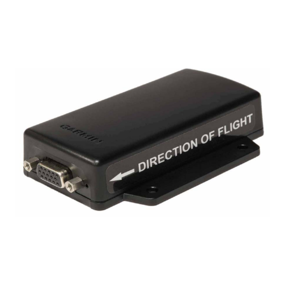
Page 11: Figure 1-1. Flight Stream Transceiver Unit View
Figure 1-1. Flight Stream Transceiver Unit View (Flight Stream 210 shown) NOTE Flight Stream 210 looks identical to the Flight Stream 110, but includes a direction of flight sticker. 190-01700-00 Flight Stream 110/210 TSO Installation Manual Rev. B Page 1-2... -
Page 12: Interface Summary And Equipment
Figure 1-2. Flight Stream Interface Block Diagram Notes: FLIGHT STREAM 210 ONLY THE FLIGHT STREAM 210 ONLY SUPPORTS A CONNECTION TO ONE GARMIN NAVIGATOR AT A TIME. IT IS RECOMMENDED TO CONNECT IT TO THE #1 NAVIGATOR OR THE GTN IN GTN/GNS INSTALLATIONS. -
Page 13: Technical Specifications
Dealer Resource Center. The Flight Stream 110 and Flight Stream 210 use the same EQF. The EQF is available directly from Garmin under the following name and part number: Garmin Flight Stream 110/210 Environmental Qualification Form, P/N 005-00818-03. 1.4.2 Physical Characteristics Table 1-3. -
Page 14: Table 1-4. Flight Stream Transceiver Specifications
Max Current @ 28 VDC Max Current @ 14 VDC 50 mA 100 mA NOTE Circuits should be protected in accordance with guidelines in AC 43.13-1B, Chapter 11, Section 4. 190-01700-00 Flight Stream 110/210 TSO Installation Manual Rev. B Page 1-5... -
Page 15: Certification
006-B1779-00 through 006-B1779-( ) Conversion of serial data from the GDL 69 to Bluetooth wireless signals 1.5.4 Design Assurance Levels This device complies with DO-178B design assurance Level E. 190-01700-00 Flight Stream 110/210 TSO Installation Manual Rev. B Page 1-6... - Page 16 European Union Declaration of Conformity: “Hereby, Garmin, declares that this Flight Stream product is in compliance with the essential requirements and other relevant provisions of Directive 1999/5/EC. To view the full Declaration of Conformity, see the www.garmin.com Garmin Web site for your Garmin product: ”.
-
Page 17: Limitations
GDL 88 TSO Installation Manual 190-01122-00 GNS 400W Series Installation Manual 190-00356-08 GNS 500W Series Installation Manual 190-00357-08 GTN 625/635/650 TSO Installation Manual 190-01004-02 GTN 725/750 TSO Installation Manual 190-01007-02 190-01700-00 Flight Stream 110/210 TSO Installation Manual Rev. B Page 1-8... -
Page 18: Installation Overview
Tie Wraps or Lacing Cord Ring Terminals (MS25036 or equivalent) Shield Terminators (MIL-S-83519 or equivalent) Silicon Fusion Tape (Garmin P/N 249-00114-00 or equivalent) Compatible portable electronic device (PED) Garmin Pilot™ App 190-01700-00 Flight Stream 110/210 TSO Installation Manual Rev. -
Page 19: Special Tools Required
615717 615725 M81969/1-04 NOTE Non-Garmin part numbers shown are not maintained by Garmin and are subject to change without notice. 2.4 Cabling and Wiring Wiring should be installed in accordance with AC 43.13-1B Chapter 11. When wire separation cannot be achieved, the following issues should be addressed: •... -
Page 20: Installation Procedure
Allow adequate space for installation of cables and connectors. All electrical connections are made through a 15-pin D-sub connector provided by Garmin. Construct the wiring harness according to the information contained in this and the following sections. Cable lengths will vary depending upon installation. -
Page 21: Figure 3-1. Connector And Backshell Assembly
Backshell Assembly Procedure The parts for the connector and backshell assembly for Flight Stream installations are listed in table 3-1 and shown in figure 3-1. Figure 3-1. Connector and Backshell Assembly 190-01700-00 Flight Stream 110/210 TSO Installation Manual Rev. B Page 3-2... -
Page 22: Figure 3-2. Shielded Cable Preparation
4. Repeat steps 6 through 8 as needed for the remaining shielded cables. 190-01700-00 Flight Stream 110/210 TSO Installation Manual Rev. B Page 3-3... - Page 23 7. Place the smooth side of the backshell strain relief across the cable bundle and secure using the two screws. WARNING Placing the grooved side of the strain relief across the cable bundle may damage wires. 8. Attach the cover to the backshell using two screws. 190-01700-00 Flight Stream 110/210 TSO Installation Manual Rev. B Page 3-4...
-
Page 24: Equipment Mounting
(Recommended on Smaller Aircraft Only) FLOOR MOUNTED BENEATH SEAT FORWARD AVIONICS BAY (NOSE) FLOOR MOUNTED BENEATH SEAT AFT AVIONICS BAY (Recommended on Smaller Aircraft Only) Figure 3-3. Suggested Mounting Locations 190-01700-00 Flight Stream 110/210 TSO Installation Manual Rev. B Page 3-5... -
Page 25: Figure 3-4. Flight Stream Mounting
Care should be taken when applying torque to the mounting screws of the Flight Stream 210. Excessive torque may damage the mounting flange. Figure 3-4. Flight Stream Mounting (Flight Stream 210 with Direction of Flight Sticker Shown) 190-01700-00 Flight Stream 110/210 TSO Installation Manual Rev. B Page 3-6... -
Page 26: Figure 3-5. Mounting Orientation
(PED). Errors in the yaw axis cannot be zeroed out. Figure 3-5. Mounting Orientation Roll Axis 190-01700-00 Flight Stream 110/210 TSO Installation Manual Rev. B Page 3-7... -
Page 27: Figure 3-6. Mounting Orientation Side View
45° 45° Figure 3-6. Mounting Orientation Side View Pitch Axis 190-01700-00 Flight Stream 110/210 TSO Installation Manual Rev. B Page 3-8... -
Page 28: Post-Installation Configuration And Checkout
The Flight Stream will also save up to twenty Bluetooth device pairings. NOTE If having issues making a Bluetooth connection, reboot the Flight Stream device. Retry making a Bluetooth connection. 190-01700-00 Flight Stream 110/210 TSO Installation Manual Rev. B Page 4-1... -
Page 29: Ground Checks
4.3 Ground Checks NOTE A compatible PED with the Garmin Pilot Application is required to perform the ground checks. 1. Check that the Flight Stream is paired with Bluetooth Device. 2. Check that Attitude is displayed on Bluetooth device (Flight Stream 210 only). -
Page 30: Software Updates
Garmin Pilot account, is required. NOTE To perform the software update, Garmin Pilot version 7.10 or later, is required. To activate Dealer Mode, contact Aviation Product Support at (888) 606-5482. Request access to update Flight Stream firmware as a Garmin Dealer. - Page 31 Figure 4-2. Garmin Pilot Settings Screen 5. Select the HOME key, then the Connext key, followed by the active Flight Stream device. Select Check for Updates. Figure 4-3. Garmin Pilot Connext Screen 190-01700-00 Flight Stream 110/210 TSO Installation Manual Rev. B Page 4-4...
- Page 32 Later depending on your preference. Figure 4-4. Firmware Update Popup 7. Select Continue and Begin Firmware Update on the following popup screens. NOTE Do not disconnect Flight Stream device while updating firmware. 190-01700-00 Flight Stream 110/210 TSO Installation Manual Rev. B Page 4-5...
- Page 33 The Flight Stream device will reboot once updated. Allow the Flight Stream device to reconnect to Garmin Pilot. 8. Verify the firmware version now displays the updated software version. Figure 4-5. Updated Flight Stream 190-01700-00 Flight Stream 110/210 TSO Installation Manual Rev.
-
Page 34: Continued Airworthiness
5 CONTINUED AIRWORTHINESS 5.1 Flight Stream 110 Maintenance of the Flight Stream 110 transceiver unit is on-condition. 5.2 Flight Stream 210 Maintenance of the Flight Stream 210 transceiver unit is on-condition. 190-01700-00 Flight Stream 110/210 TSO Installation Manual Rev. B Page 5-1... -
Page 35: Connector Pinout Information
The Flight Stream accepts input power from 9.5 to 33 VDC. The power input pins are connected to the aircraft power bus through a single circuit breaker. See appendix B for recommended power connections. Table 6-2. Aircraft Power Pin # Name Aircraft Power Ground 190-01700-00 Flight Stream 110/210 TSO Installation Manual Rev. B Page 6-1... -
Page 36: Table 6-3. Rs-232
Volume Lock Discrete Input* An asterisk (*) following a signal name denotes the signal is an Active-Low, requiring a ground to activate. If there is no asterisk, the signal is an Active-High. 190-01700-00 Flight Stream 110/210 TSO Installation Manual Rev. B Page 6-2... -
Page 37: Troubleshooting
210 is connected to a display), and then attempt to pair the device again. Flight Stream Attitude Behavior Appears Check that Flight Stream is mounted with arrow pointing Backwards (Flight Stream 210 only) in direction of flight. 190-01700-00 Flight Stream 110/210 TSO Installation Manual Rev. B Page 7-1... -
Page 38: Appendix Aoutline And Installation Drawing
APPENDIX A OUTLINE AND INSTALLATION DRAWING 2.28 1.37 0.43 0.91 3.16 3.78 2.00 5.75 4 X 0.1622 DIA 2.74 0.92 Figure A-1. Flight Stream Transceiver Dimensions 190-01700-00 Flight Stream 110/210 TSO Installation Manual Rev. B Page A-1... -
Page 39: Appendix Binterconnect Drawings
APPENDIX B INTERCONNECT DRAWINGS Figure B-1. Flight Stream 110/210 - Power Interconnect Figure B-2. Flight Stream - GDL 69/69A Interconnect Figure B-3. Flight Stream - GDL 88 Interconnect Figure B-4. Flight Stream 210 - GNS Interconnect Figure B-5. Flight Stream 210 - GTN 6XX/7XX Interconnect Figure B-6. - Page 40 NOTES CIRCUIT BREAKER SHOULD BE LABELED AS SHOWN. GROUND DESIGNATIONS: SHIELD BLOCK GROUND AIRFRAME GROUND Figure B-1. Flight Stream 110/210 - Power Interconnect 190-01700-00 Flight Stream 110/210 TSO Installation Manual Rev. B Page B-2...
- Page 41 THE VOLUME LOCK DISCRETE MAY OPTIONALLY BE CONNECTED OR SWITCHED TO GROUND. THIS WILL FORCE THE FLIGHT STREAM TO IGNORE SIRIUSXM SATELLITE RADIO VOLUME COMMANDS FROM WIRELESS DEVICES. Figure B-2. Flight Stream - GDL 69/69A Interconnect 190-01700-00 Flight Stream 110/210 TSO Installation Manual Rev. B Page B-3...
- Page 42 ANY RS-422 PORT MAY BE CONNECTED IN LIEU OF THESE PORTS. FOR ADDITIONAL DETAILS, REFER TO THE GDL 88 INSTALLATION MANUAL, PART NUMBER 190-01122-00. Figure B-3. Flight Stream - GDL 88 Interconnect 190-01700-00 Flight Stream 110/210 TSO Installation Manual Rev. B Page B-4...
- Page 43 AND GNS 500W INSTALLATION MANUALS, PART NUMBERS 190-00356-08 AND 190-00357-08 RESPECTIVELY, FOR RS-232 SETTINGS. THE FLIGHT STREAM 210 ONLY SUPPORTS A CONNECTION TO ONE GARMIN NAVIGATOR AT A TIME. IT IS RECOMMENDED TO CONNECT IT TO THE #1 NAVIGATOR OR THE GTN IN GTN/GNS INSTALLATIONS.
- Page 44 ANY RS-232 PORT MAY BE CONNECTED IN LIEU OF THESE PORTS. REFER TO THE GTN INSTALL MANUAL FOR RS-232 SETTINGS. THE FLIGHT STREAM 210 ONLY SUPPORTS A CONNECTION TO ONE GARMIN NAVIGATOR AT A TIME. IT IS RECOMMENDED TO CONNECT IT TO THE #1 NAVIGATOR OR THE GTN IN GTN/GNS INSTALLATIONS.
- Page 45 THE FLIGHT STREAM 210 SUPPORTS BOTH HIGH AND LOW SPEED ARINC 429 CONNECTIONS ON THE ARINC 429 INPUT PORT. THE FLIGHT STREAM WILL AUTO-DETECT THE SPEED. NO CONFIGURATION IS NECESSARY. Figure B-6. Flight Stream 210 - ARINC 429 Interconnect 190-01700-00 Flight Stream 110/210 TSO Installation Manual Rev. B Page B-7...
Need help?
Do you have a question about the Flight Stream 110/210 and is the answer not in the manual?
Questions and answers