Table of Contents
Advertisement
Quick Links
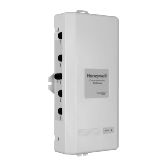
W8735G Communication Gateway
APPLICATION
For use with Remote Access applications monitoring
EnviraCOM™ enabled controls and sensors. Communicates
with up to four EnviraCOM™ buses for multiple appliance
installations.
COMPONENTS AND
ACCESSORIES
• R7184 Oil Primary
• R7284 Oil Primary
• L7224 Aquastat®
• L7248 Aquastat®
• TH9421C VisionPRO® IAQ
• W8735S1016 Indoor Temperature Module for temperature
indication and alerting.
INSTALLATION INSTRUCTIONS
FEATURES
• Monitors the bus for critical events and updates the
server.
• Monitors system power and generates power failure
alarms.
• Battery backup.
• Monitor up to four separate appliances.
• Updates via phone line or network.
• Auxiliary I/O.
• Remote firmware updates.
When Installing This Product...
1. Read these instructions carefully. Failure to follow the
manual could damage the product.
2. Installer must be a trained, experienced service techni-
cian.
3. Complete all wiring connections to the gateway before
powering up the 24Vac system transformer and plug-
ging in the gateway power supply into an outlet.
4. All wiring must comply with applicable local electrical
codes, ordinances and regulations.
INSTALLATION
Mount the W8735G in the equipment room near the indoor
HVAC equipment. Position the W8735G vertically so that the
power and telephone plugs are situated towards the bottom or
horizontally so that all wiring terminations face the floor,
depending on the space available. See Fig. 1.
IMPORTANT
Turn OFF all power to heating and cooling equip-
ment.
1. Position the W8735G on a wall near the indoor HVAC
equipment. Level the module for appearances only; the
module functions properly even when not level.
2. Use a pencil to mark the mounting holes to be used.
The W8735G has two external mounting holes and two
external flanges. See Fig. 2.
3. Use a minimum of one hole and one flange to mount the
W8735G.
69-2432-01
Advertisement
Table of Contents

Related Manuals for Honeywell W8735G


Summary of Contents for Honeywell W8735G
-
Page 1: Installation Instructions
• L7224 Aquastat® ment. • L7248 Aquastat® • TH9421C VisionPRO® IAQ 1. Position the W8735G on a wall near the indoor HVAC • W8735S1016 Indoor Temperature Module for temperature equipment. Level the module for appearances only; the indication and alerting. -
Page 2: General Wiring Directions
W8735G COMMUNICATION GATEWAY 4. Remove the W8735G from the wall and drill a minimum of two 3/16-in. holes in the wall (if drywall) as marked. For firmer material such as plaster, drill a minimum of two 7/32-in. holes. 5. When mounting to the wall, gently tap provided anchors into the drilled holes until flush with the wall. - Page 3 1/D (channel 4) To EnviraCOM channel 4 network; DATA 2/R (channel 4) To EnviraCOM channel 4 network; 24 Vac Hot 3/B (channel 4) To EnviraCOM channel 4 network; 24 Vac Common See Fig. 5 for a typical W8735G application. 69-2432—01...
-
Page 4: W8735G Gateway Led Codes
24 Vac/Vdc thermostats can be connected to the The Auxiliary contacts are available to integrate non- Auxiliary Input contacts to integrate non-EnviraCOM devices EnviraCOM sensors and switches to the W8735G and to to the W8735G. allow the W8735G to interface with non-EnviraCOM monitoring devices in case an alert condition is detected. -
Page 5: Auxiliary Input And Output Applications
• Connect a 24 Vac/dc sensor. See Fig. 11. The Auxiliary Output closes in the event an alert condition is detected from the W8735G or from the Auxiliary Input. The AUXILIARY OUTPUT (AUX-OUT) TERMINAL Auxiliary Output (dry) contacts remain closed until the alert •... - Page 6 W8735G COMMUNICATION GATEWAY CHANNEL 1 CHANNEL 1 CHANNEL 2 CHANNEL 2 T87 OR SIMILAR N.C. OUTPUT OUTPUT N.C. AUXILIARY AUXILIARY INPUT INPUT COMBINATION OF DEVICES CONNECTED IN PARALLEL TO POWER FROM THE AUXILIARY INPUT SUPPLIED BY TRANSFORMER. ANNUNCIATE ON AN “AND” EVENT ON THE AUX-IN LOOP.
-
Page 7: Phone/Network Communication
If the gateway fails to connect while attempting to deliver an alarm report, it will retry at five minute intervals until successful. The W8735G also reports a runtime data log for the bus or CHANNEL 1 busses it is monitoring. During a 24 hour period, a W8735G... -
Page 8: Battery Replacement
Battery Replacement Some installations may require a 9 prefix be dialed in order to gain a dial tone. The W8735G supports this feature by way of IMPORTANT the preset jumper. See Fig. 15. When this jumper is in place, a For best performance replace the 9V battery yearly “9”...
Need help?
Do you have a question about the W8735G and is the answer not in the manual?
Questions and answers