Table of Contents
Advertisement
MV21 Installation Guide
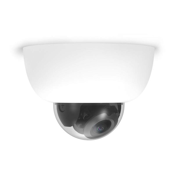
MV21 Overview
The Cisco Meraki MV21 is a networked camera that is exceptionally simple to deploy and configure due to its integration
into the Meraki dashboard and the use of cloud augmented edge storage. The MV family eliminates the complex and
costly servers and video recorders required by traditional solutions which removes the limitations typically placed on
video surveillance deployments.
Package Contents
In addition to the MV camera, the following are provided:
Ethernet Port
The MV21 features a 100BASE-TX Ethernet port that supports 802.3af PoE.
1
Advertisement
Table of Contents

Related Manuals for Cisco Meraki MV21


Summary of Contents for Cisco Meraki MV21
-
Page 1: Package Contents
MV21 Overview The Cisco Meraki MV21 is a networked camera that is exceptionally simple to deploy and configure due to its integration into the Meraki dashboard and the use of cloud augmented edge storage. The MV family eliminates the complex and costly servers and video recorders required by traditional solutions which removes the limitations typically placed on video surveillance deployments. -
Page 2: Pre-Install Preparation
Pre-Install Preparation You should complete the following steps before going on-site to perform an installation. Configure Your Network in Dashboard The following is a brief overview only of the steps required to add an MV21 to your network. For detailed instructions about creating, configuring and managing Meraki Camera networks, refer to the online documentation (https://documentation.meraki.com/MV). -
Page 3: Installation Instructions
Installation Instructions Note: Each MV21 comes with an instruction pamphlet within the box. This pamphlet contains detailed step by step guides and images to assist in the physical install of the camera. A pdf of the pamphlet can be found here. Note: During first time setup, the MV21 will automatically update to the latest stable firmware. - Page 4 3. Screw the mounting plate onto the wall in pre-determined locations. Use template holes marked with the letter “A” for standard wall mounting. 4. Connect PoE cable to camera. For cords that will exit the top of the camera, loop the cable inside the camera as shown.
- Page 5 5. Slide camera over top of mount plate and slide down into mount plate hooks. Secure with Phillips or Torx head safety screw. 6. Turn bubble counter clockwise to unlock. Hinge bubble off of body to remove. 7. Pinch near thumb screws and pull straight away from the camera to remove lens guard.
- Page 6 8. Aim the lens. Look through the camera on the Meraki Dashboard to fine tune the picture. The camera sensor and lens unit can be physically tilted through a range of 65 degrees, rotated through a range of 350 degrees, and panned through a range of 350 degrees.
-
Page 7: T-Rail Mounting Instructions
10. Remove protective plastic sticker. Check LED function. Use the Meraki Dashboard to adjust camera focus and configure other settings. T-rail Mounting Instructions To mount your MV21 on a drop ceiling T-rail, use the included hardware. The hardware can be used to mount to most 9/ 16”, 15/16”, or 1 ½”... - Page 8 2. Tighten the set screws on the T-rail clips and secure them using a 5/64” (2 mm) hex key. 3. Attach the mount plate to the T-rail clips using the mount plate holes (marked with a “G”).
- Page 9 4. Attach the T-rail clips to the T-rail by rotating them and snapping them into place as shown. The black foam pads should be compressed slightly after installation.
-
Page 10: Powering The Mv21
Powering the MV21 Remove the cable guard and route the Ethernet cable from an active port on a 802.3af PoE switch or PoE injector. Note: Power over Ethernet supports a maximum cable length of 300 ft (100 m). LED Indicator Your MV21 is equipped with a LED light on the front of the unit to convey information about system functionality and performance: •...
Need help?
Do you have a question about the Meraki MV21 and is the answer not in the manual?
Questions and answers