Advertisement
Quick Links
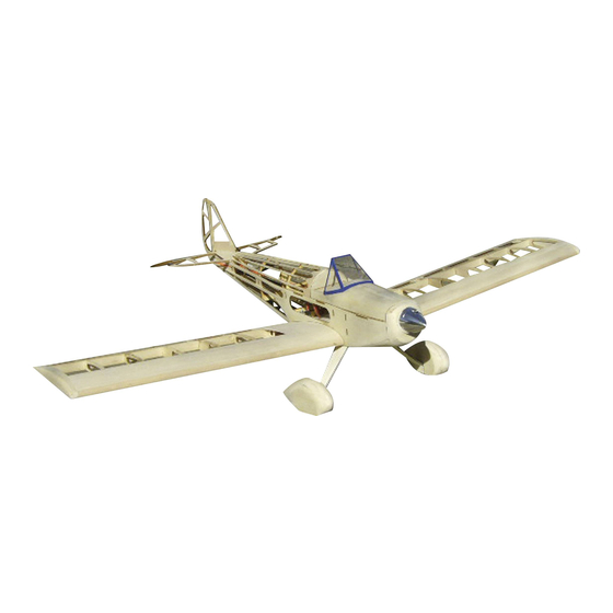
Spacewalker
Instruction
Read these instructions carefully before use.
Please keep these instruction after assembling.
Safety precautions
!
This radio control model is not a toy!
Not suitable for persons under 14 years!
* First-time builders should seek advice people having
building experience in order to assemble the model
correctly and to produce its performance to full extent.
* Assemble this kit only in places out of children's reach!
* Take enough safety precautions prior to operating this
model. You are responsible for this model's assembly and
safe operation!
* Always keep this instruction manual ready at hand for
quick reference, even after completing the assembly.
GB
00 6137
Ord. No.
Advertisement

Related Manuals for Jamara Spacewalker


Summary of Contents for Jamara Spacewalker
-
Page 1: Safety Precautions
Spacewalker 00 6137 Instruction Ord. No. Read these instructions carefully before use. Please keep these instruction after assembling. Safety precautions This radio control model is not a toy! Not suitable for persons under 14 years! * First-time builders should seek advice people having building experience in order to assemble the model correctly and to produce its performance to full extent. -
Page 2: Safety Information
Attention! In some countries it is a legal requirement to carry third Party As the company JAMARA e.K. has no influence over the use, main- tenance or conditions under which our products will operate, we indemnity insurance when operating a radio controlled mo- accept no responsibility for any damage caused be it of a physical, del. - Page 3 Kit Contents: • CNC LASER cut formers and ribs, strip wood, selected light weight balsa sheet and aircraft grade plywood. • Fitting kit including wheels, undercarriage, horns and hinges. • Clear canopy. • Instructions. For the drive-in nut to have more support, the holes are Doubled the undercarriage mount. doubled with a ply ring. Insert the nuts from the top and secure with a little glue.
- Page 4 Wing support, rib and screw holder are mounted. Turn the frame. The battery board and motor support are vertical to each 8. Side pieced are glued. The top balsa piece (cockpit back plate) other and mounted to the frame. is glued. Insert the both left over fuselage pieces. Every part should be 10.
- Page 5 11. 3 x 4 mm borders (brown edge facing up) are glued.. Tip: The borders are 1 mm further up compared to the frame. They are sanded slightly. 12. A border is glued to the centre of the underside. Looking at part F4, it is sanded from the border to the outside.
- Page 6 17. The fuselage nose is sanded. 18. Lay the lid frame in the fuselage and placed the balsa pieces on top. To prevent lid frame being stuck to the fuselage, a sheet of paper or plastic wrap is placed in between. 3 x 4 mm strips are drawn (note position).
- Page 7 23. To bend the undercarriage wire, use the cut-out from the 24. It is recommended to apply a dummy empennage made of support as reference. 4 mm balsa rest. It is applied and removed later. This will help you to align the empennage. 25.
- Page 8 Zusammenbau 29. The Bowden wire (not incl.) is installed. 30. Assembly elevator and rudder servo. 31. Carve 1,5mm into the ribs the covering foil will lay on later. 32. Mount the rear wheel wire to the rudder. This will avoid edges in the foil later on. 33.
- Page 9 35. Template for cockpit window. 36. The cockpit window is folded along the diagonal edge. 37. The undercarriage covering is made of 3 layers of balsa. The 38. Last step is to apply a 1,5 mm balsa piece and sand all edges. first piece is made of 1,5 mm balsa with a little overlay.
- Page 10 Zusammenbau 41. Sanded wheel pants. 42. The rudders are sanded either on one side for paper hinges or both sides for plastic hinges.. 43. Supports for the wing spar are glued into place. 44. Ribs are applied to the wing spar in sequence R2 – R9. 45.
- Page 11 47. The servo frame is 1,5 mm higher than the wing spar. The 48. Rib No. 1 in a right angle to the wing spar. planking later one will even it out. 49. Some ribs are higher than the wing spar. Also this part is 50.
- Page 12 Zusammenbau 53. If all is dried, start with the inner/ lower planking. 54. The final edge is filled approx 25 mm upwards so the wing screws do not push through. 55. Final edge and ribs are supported with small balsa triangles. 56.
- Page 13 59. Sand the final edge. 60. The tip is made of 4 layers with 6 mm wood each layer. 61. Sand the curved edge. 62. Curved edge 63. Now the curved edge is sanded right to its original shape. 64. Cut out the aileron and sand it.
- Page 14 Zusammenbau 65. Now the wings can be put together. 66. If the main wings do not fit the fuselage… 67. … a 4 mm piece of wood is applied until… 68..… the main wings fit the fuselage nicely. 69. To avoid creases in the covering foil around the rudder horn, 70.
- Page 15 71. Assemble the elevator and rudder servo as shown. 72 The finished build shell. Set-up: Aileron: 10 mm deflection Elevator: 10 mm deflection Rudder: 25 mm deflection 40 mm from the nose Down thrust ~ 2° down (already installed) Traction ~ 2 - 2,5° to the right (depending on motor and propeller) Recommended Accessories Ord.
- Page 16 Plane - The original sized plan can be found on the DVD...
- Page 17 Plane - The original sized plan can be found on the DVD Main wings...
- Page 18 Plane - The original sized plan can be found on the DVD Fuselage...
- Page 20 All rights reserved. Copyright JAMARA e.K. 2011 Copying or reproduction in whole or part, only with the expressed permission of JAMARA e.K. Coupon Order the current catalogue with our complete assortment of modelling goods today. Name _______________________________ First name _______________________________...
Need help?
Do you have a question about the Spacewalker and is the answer not in the manual?
Questions and answers