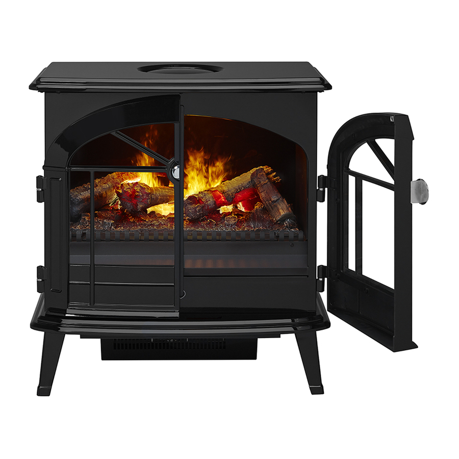
Table of Contents
Advertisement
IMPORTANT SAFETY INFORMATION: Always read this manual first before attempting to service this cassette. For your
safety, always comply with all warnings and safety instructions contained in this manual to prevent personal injury or prop-
erty damage.
Dimplex North America Limited
1367 Industrial Road Cambridge ON Canada N3H 4W3
1-888-346-7539 www.dimplex.com
In keeping with our policy of continuous product development, we reserve the right to make changes without notice.
© 2016 Dimplex North America Limited
Service Manual
Model
OS2527GB
Part Number
6909560100
REV
PCN
DATE
00
-
15-NOV-16
7400750000R00
Advertisement
Table of Contents

Summary of Contents for Dimplex OS2527GB
- Page 1 Dimplex North America Limited 1367 Industrial Road Cambridge ON Canada N3H 4W3 15-NOV-16 1-888-346-7539 www.dimplex.com In keeping with our policy of continuous product development, we reserve the right to make changes without notice. © 2016 Dimplex North America Limited 7400750000R00...
-
Page 2: Table Of Contents
NOTE: Procedures and techniques that are considered important enough to emphasize. CAUTION: Procedures and techniques which, if not carefully followed, will result in damage to the equipment. WARNING: Procedures and techniques which, if not carefully followed, will expose the user to the risk of fire, serious injury, or death. www.dimplex.com... -
Page 3: Operation
CAUTION: If you need to continuously reset the heater, To adjust the temperature to your individual requirements, unplug the unit and call Dimplex North America Limited at turn the thermostat control clockwise all the way to turn on 1-888-346-7539 for technical support. Please have your the heater. -
Page 4: Maintenance
! NOTE: Replacement light bulbs can be obtained by Except for installation and cleaning described in this manu- contacting Dimplex Customer Service at 1-888-346-7539. al, an authorized service representative should perform any 6. Carefully insert the two pins of the new bulb into the other servicing. -
Page 5: Exploded Parts Diagram
EXPLODED PARTS DIAGRAM REPLACEMENT PARTS LIST 15. On/Off Switch ....9600383500RP 1. Remote Control ....9600385600RP 16. -
Page 6: Wiring Diagram
WIRING DIAGRAM GROUND THERMAL CUTOUT THERMOSTAT LINE IN TRANSFORMER NEUTRAL TRANSFORMER POWER BOARD POTENTOMETER IR SENSOR TRANSDUCER FAN MOTOR www.dimplex.com... -
Page 7: Remote Control Receiver Replacement
REMOTE CONTROL RECEIVER Figure 4 REPLACEMENT Tools Required: Phillips head screwdriver Flat Head Screwdriver Transformers WARNING: Disconnect power before attempting any maintenance to reduce the risk of electric shock or damage to persons. NOTE: Ensure that all of the components that contain water have been emptied before performing any maintenance. -
Page 8: Thermostat Replacement
4. Inside of the unit remove the two screws that secure 10. Re-assemble the remainder of the cassette in reverse the cassette assembly to the chassis. order from the instructions above. 5. Lift the cassette assembly out of the unit. www.dimplex.com... -
Page 9: Fuse / Fuse Assembly Replacement
6. Remove the 4 screws that secure the front grill to the Figure 5 cassette housing. (Figure 4) 7. Locate the cord and disconnect the wiring connections noting their original locations. NOTE: A flat head screwdriver can be used to gently pry between the end of the connector and the switch to release the wires. -
Page 10: Heater Assembly Replacement
5. Remove the 2 screws on the top of the assembly, 2 on the bottom on either side and 2 on either side of the heater outlet. 6. Set the top panel up against the bottom of the stove. www.dimplex.com... -
Page 11: Troubleshooting Guide
TROUBLESHOOTING GUIDE PROBLEM CAUSE SOLUTION General Unpleasant smell when unit is Dirty or stale water. Clean the unit as described under maintenance. used. Appearance Fireplace does not turn on Manu- Improper operation Refer to Operation Section ally No incoming voltage from the electrical wall Check Fuse/Breaker Panel socket Defective 3 Position Switch... - Page 12 Normal Operation Normal operation is when the heater emits an odor for a brief period after the heater is initially turned on. The heater is burning off any dust accumulated during manufacturing or operation. Defective Heater Assembly Replace Heater Assembly www.dimplex.com...


Need help?
Do you have a question about the OS2527GB and is the answer not in the manual?
Questions and answers