Advertisement
INSTRUCTION MANUAL
INSTRUCTION MANUAL
INSTRUCTION MANUAL
INSTRUCTION MANUAL
M M M M
P P P P
OTOR
OTOR
OTOR
OTOR
2464 Vulcan Road
Apopka, Florida 32703
C A Briggs
Order from:
Phone: 267-673-8117 - 800-352-6265 - Fax: 267-673-8118; E-Mail:
SC100
SC100
SC100
SC100
ROTECTION
ROTECTION
ROTECTION
ROTECTION
Company;
622 Mary Street; Suite 101 - Warminster, PA 18974
E E E E
LECTRONICS, INC.
LECTRONICS, INC.
LECTRONICS, INC.
LECTRONICS, INC.
Phone:
(407) 299-3825
Website:
www.mpelectronics.com
Revision Date: 6-23-14
Sales@cabriggs.com
-
www.cabriggs.com
Advertisement
Table of Contents

Related Manuals for MPE SC100


Summary of Contents for MPE SC100
- Page 1 SC100 SC100 SC100 SC100 INSTRUCTION MANUAL INSTRUCTION MANUAL INSTRUCTION MANUAL INSTRUCTION MANUAL M M M M P P P P E E E E OTOR OTOR OTOR OTOR ROTECTION ROTECTION ROTECTION ROTECTION LECTRONICS, INC. LECTRONICS, INC. LECTRONICS, INC. LECTRONICS, INC.
-
Page 2: Specifications
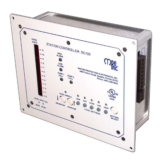
4-20 mA, 250 Ohms Load Transient Protected Color: White with Blue Lettering Enclosure Material: Aluminum ORDERING INFORMATION: 5psi Transducer used with: SC100-05 SC100 - XX 10psi Transducer used with: SC100-10 15psi Transducer used with: SC100-15 Product Type Scale Range 05 = 11.5 Ft/H2O For Pump Up Applications (Fill a Tank) 10 = 23.1 Ft/H2O... - Page 3 VIEW OR CHANGE LEVEL SETTINGS Menu: To enter the menu press the Setting Select pushbutton once. To move in the menu from left to right, press the Setting Select pushbutton again. To exit the menu, press the Setting Select pushbutton once while at the right most end of the menu. Viewing Settings: When the menu indicator over one of the Level Setting potentiometers is on, the current setting will be shown on the bar graph display.
-
Page 4: Level Display
The Level Display Scale shows level in feet of water. In order for the level to be accurate, the cor- rect pressure transducer must be used with the controller. The following shows which pressure transducer goes with the different controllers: Part Number Transducer Calibration Scale Range SC100-05 11.5 Ft/H2O 20mA at 5 psi SC100-10 23.1 Ft/H2O... -
Page 5: Electrical Connection Diagram
ELECTRICAL CONNECTION DIAGRAM LEVEL INPUT CONNECTION DIAGRAMS SUBMERSIBLE PRESSURE TRANSDUCER CONNECTION BUBBLER SYSTEM BS2000 CONNECTION... - Page 6 CONTROL SCHEMATIC EXAMPLE – DUPLEX With 24V Float Backup...
- Page 7 ENCLOSURE MECHANICAL LAYOUT...
-
Page 8: Panel Cutout
PANEL CUTOUT Not Printed to Scale. Do Not Use as a Template.
Need help?
Do you have a question about the SC100 and is the answer not in the manual?
Questions and answers