Table of Contents
Advertisement
Quick Links
INSTRUCTION MANUAL
M
P
OTOR
2464 Vulcan Road
Apopka, Florida 32703
Operating Program Revision: 8
C A Briggs
Order from:
Phone: 267-673-8117 - 800-352-6265 - Fax: 267-673-8118; E-Mail:
SC1000
ROTECTION
Company;
622 Mary Street; Suite 101 - Warminster, PA 18974
E
LECTRONICS, INC.
Phone:
Fax:
Revision Date: 5-16-11
Sales@cabriggs.com
-
www.cabriggs.com
(407) 299-3825
(407) 294-9435
Advertisement
Table of Contents

Subscribe to Our Youtube Channel
Related Manuals for MPE SC1000


Summary of Contents for MPE SC1000
- Page 1 SC1000 INSTRUCTION MANUAL OTOR ROTECTION LECTRONICS, INC. 2464 Vulcan Road Phone: (407) 299-3825 Apopka, Florida 32703 Fax: (407) 294-9435 Operating Program Revision: 8 Revision Date: 5-16-11 C A Briggs Company; Order from: 622 Mary Street; Suite 101 - Warminster, PA 18974 Phone: 267-673-8117 - 800-352-6265 - Fax: 267-673-8118;...
-
Page 2: Specifications
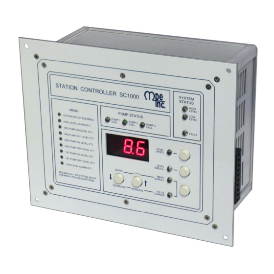
- Latest Inflow Rate - Average Daily Inflow Total (Average of Last 7 Days) - Pump Outflow Rate (Latest for Each Pump) Part Number: SC1000 - X X Blank = RS232 Port OPTIONAL FEATURES E = RS232 Port & Ethernet Port •... - Page 3 OPERATOR INTERFACE FUNCTIONS On when Display Shows the Wet Well Level Press to Display Wet Well Level On when in Level Simulation Mode Press to Enter the Level Simulation Mode On when in Menu Scroll Mode Press to Change Function of the Up/Down Push-Buttons On when in Value Change Mode Press to Scroll Up the Menu, or to...
-
Page 4: Menu - System Setup
MENU - SYSTEM SETUP All Level Settings Have the Decimal Point Artificially Inserted Based on Parameter P.36. Default Current Parameter Value Value Setting Definitions Low Level Alarm Range: 0.1 - 99.9 feet SCADA Register 40021 2.0 feet Note: To Disable Alarm see Parameter P.50. 3.0 feet 1st Pump Off Level Range: 0.2 - 99.9 feet... -
Page 5: Setting Definitions
MENU - SYSTEM SETUP All Level Settings Have the Decimal Point Artificially Inserted Based on Parameter P.36. Default Current Parameter Value Value Setting Definitions P.33 Register Access Mode See Page 19 Stop Pump Delay Range: 1 - 100 seconds P.35 1 sec. - Page 6 MENU - SYSTEM SETUP All Level Settings Have the Decimal Point Artificially Inserted Based on Parameter P.36. Default Current Parameter Value Value Setting Definitions Discrete Input 1 F.01 Function of Input: Connect To: Function 0 = No Function 1 = Pump 1 Disable …….………...…………...…. HOA and Fault Logic Discrete Input 2 2 = Pump 2 Disable …….…..…..……….….…..
- Page 7 MENU - SYSTEM SETUP Default Current Parameter Value Value Setting Definitions HI Relay Output Function F.31 0 = Disabled 1 = High Level Alarm 2 = Remote Control (SCADA Coil 25) Note: High Level indicator on front of unit will operate regardless of setting. LO Relay Output Function F.32 0 = Disabled...
- Page 8 MENU - DATA DISPLAY Parameter Data Description L.01 Electrode 1 Status Value L.02 Electrode 2 Status Value Level Probe Electrode Status Values Normal Range when Un-Covered: 240 - 255 L.03 Electrode 3 Status Value Normal Range when Covered by Typical Sewage: 55 - 70 L.04 Electrode 4 Status Value...
- Page 9 MENU - DATA DISPLAY Parameter Data Description n.01 Discrete Input 1 Status n.02 Discrete Input 2 Status Discrete Input Status n.03 Discrete Input 3 Status n.04 Discrete Input 4 Status 0 = Input Open n.05 Discrete Input 5 Status 1 = Input Closed n.06 Discrete Input 6 Status n.07...
- Page 10 ALTERNATION SEQUENCE STANDARD ALTERNATION Parameter P.16 = 1 Notes: 1. Unless there is some special circumstance that requires a more complicated Movement of Lead Pump Upon Alternation pump call sequence, this is the sequence that should be used. 2. Parameter P.17 must be used to select either First On Last Off or First On First Off.
- Page 11 ALTERNATION SEQUENCE PUMP 1 ALWAYS LEAD Turns Off With Other Pumps On Parameter P.16 = 3 Notes: 1. This sequence is used when it is required that pump 1 always be lead, and when it must be turned off when another pump(s) comes on. When a pump Movement of Lead Pump Upon Alternation from the second group is required, pump 1 is first turned off, then after the Lag Pump Delay, the other pump is turned on.
- Page 12 ALTERNATION SEQUENCE FIXED ALTERNATION Parameter P.16 = 5 Notes: 1. This sequence is used when no alternation is required and when pump 1 should normally be lead pump. Other pumps may be made lead by setting Parameter P.39. 2. Discrete Inputs programmed as Pump 1-3 Disable inputs may be used to disable pumps.
-
Page 13: System Status
SYSTEM STATUS High Level Alarm • Upon a High Level Alarm, the indicator will come on and the relay contacts will close. • A High Level Alarm is delayed for ten seconds after power is applied. • The High Level Alarm relay contacts will be closed when there is no power on the controller. •... -
Page 14: Fault Code Table
FAULT CODE TABLE Fault Code Description of Condition Normal Communication Fault - Overrun Error reading incoming message. Communication Fault - Time out error reading incoming message. Communication Fault - Time out error responding to message. Communication Fault - Incoming message failed Checksum Test. Communication Fault - Invalid Modbus Function Code. - Page 15 FAULT CODE TABLE Fault Code Description of Condition Communication Fault - Write Attempt to Register Not Marked for “Write” using Function Code No. 05. Communication Fault - Write Attempt to Register Not Marked for “Write” using Function Code No. 06. Communication Fault - Write Attempt to Register Not Marked for “Write”...
-
Page 16: Calibration Procedure
ANALOG LEVEL INPUT – CALIBRATION PROCEDURE (4-20mA Input) The following calibration is for the 4-20mA Analog Level Input (Parameter F.19 = 1) and does not apply when a 10 Electrode Level Probe is used (Parameter F.19 = 2). Parameters P.24 and P.25 show the Wet Well Level, while allowing the Up & Down push-buttons to be used to change the internal numbers involved in calculating the displayed level. -
Page 17: Flush Cycle
FLUSH CYCLE The Flush Cycle feature is provided to periodically maximize the lift station’s discharge flow rate, to flush the sludge build up from the bottom of the wet well and from the discharge pipe. Flush Cycle may be started by one of the following ways: A. - Page 18 FLOW CALCULATOR Latest Inflow Rate - The Most Recently Determined Flow Rate into the Lift Station The Flow Calculator determines the “Latest Inflow Rate” of liquid flowing into the lift station by observing how long it takes for the wet well level to rise a “known distance”, while all pumps are off. Knowing the sur- face area of the wet well (Parameter P.46), the volume of liquid per minute flowing into the wet well is calcu- lated.
- Page 19 FLOW CALCULATOR - Surface Area Calculation Gallons = 7.48052 x Cubic Feet Rectangular Wet Well Circular Wet Well Area = Length x Width Where Length & Width Measurements are in: Feet Where Diameter is in: Feet FLOW CALCULATOR - Display Parameters Display Range: 0 - 65,535 Latest Inflow Rate SCADA Register: 40080...
- Page 20 COMMUNICATION WITH A SCADA SYSTEM A SCADA system may communicate with the controller through either the RS232 Serial Port or through the Optional Ethernet Port. The controller operates as a MODBUS slave, where all communication is initiated by the MODBUS master. MODBUS Functions Supported Function Code...
-
Page 21: Rs232 Serial Port
RS232 SERIAL PORT The RS232 serial port allows a SCADA system to communication with the ISD using the Modbus RTU protocol. Setup of RS232 Serial Port The controller’s RS232 serial port must be setup to communicate with the device it is connected to. The Baud Rate, Parity Mode and Stop Bits Parameter values of the two devices must be set to match. -
Page 22: Ethernet Port - Option
ETHERNET PORT - Option Features The Ethernet Port has the following features: • Protocols Supported: Modbus TCP or Modbus RTU • IEEE 802.3 Compliant • Auto-Negotiation of Communication Speed to either 10 or 100 Mbps • Auto-Negotiation of either Half or Full-Duplex operation •... - Page 23 SCADA REGISTERS Description of Register Contents (Where a Coil is represented by a Bit in a Register) Coil 40001 √ Coil 40002 √ √ 40003 √ Pump 1 Elapsed Time Meter (hours and 1/10 hours) Range: 0.0 - 6553.5 hours 40004 √...
- Page 24 Coil 160 159 158 157 156 155 154 153 152 151 150 149 148 147 146 145 40010 √ √ 40011 √ Wet Well Level (As shown on display with no decimal point) 40012 √ √ Setup Parameter - 1st Pump On Level 40013 √...
- Page 25 40047 √ Fault Code (Same as Parameter FLC) 40048 √ Last Fault Code (Same as Parameter LFC) 40049 √ Voltage of +5 Volt Power Supply (Same as Parameter d.01) 40050 √ Voltage of +24 Volt Power Supply (Same as Parameter d.02) 40063 √...
- Page 26 SCADA FEATURES Wet Well Level The Wet Well Level may be monitored by reading Register 40011. The value will be just what is displayed on the front of the controller but with no decimal point. Discrete Inputs The status of all the Discrete Inputs may always be read from Coils 545 - 552 in Register 40035, and Coils 561 - 564 in Register 40036, regardless of what function may be assigned to the inputs.
-
Page 27: Fault Codes
SCADA FEATURES Remote Control of Relays Relays that are not needed for pump control or alarm outputs, may be controlled remotely by setting their Output Func- tion (Parameters F.31 - 35) to 2 . Remote control is accomplished by setting or clearing Coils 25 - 29 in Register 40002. Upon a loss of serial communication, Coils 25 - 29 will automatically be cleared after the delay set on Parameter P.38. - Page 28 SCADA TROUBLESHOOTING Communication Activity Indicatior The Communication Activity Indicator (Parameter d.07) may be used to help troubleshoot communication issues. It typically pulses from “0” to “1” momentarily to indicate that the master is sending a message. It may stay “1” if there is very little time between messages.
- Page 29 CONNECTION DIAGRAM - STANDARD FEATURES...
- Page 30 CONNECTION DIAGRAM - LEAD PUMP SELECTOR SWITCH...
- Page 31 CONNECTION DIAGRAM - ANALOG LEVEL INPUT (4-20mA Input)
- Page 32 CONNECTION DIAGRAM - LEVEL PROBE...
- Page 33 LEVEL PROBE - PLACEMENT and SETUP...
- Page 34 CONTROL SCHEMATIC EXAMPLE - Duplex with 24V Float Backup...
- Page 35 FLOAT BACKUP EXAMPLE - Pump Down Notes: 1. Pump Down Applications (Parameter P.19 = 1) Two Float Backup - A simple two float backup system can be made using an Off float and a High float. High Level Input - Closure of the Float Backup High Level input will cause all pumps to be called to run, provided the Off float input is closed.
-
Page 36: Operator Interface
OPERATOR INTERFACE... - Page 37 ENCLOSURE MECHANICAL LAYOUT Left Side Right Side Rear View Top View...
-
Page 38: Panel Cutout
PANEL CUTOUT...
Need help?
Do you have a question about the SC1000 and is the answer not in the manual?
Questions and answers