Table of Contents
Advertisement
Quick Links
Download this manual
See also:
Operating Manual
Advertisement
Table of Contents

Related Manuals for Veripos LD5

Summary of Contents for Veripos LD5
- Page 1 LD5 (C Variant) Operations Manual VERIPOS...
- Page 2 28.03.2019 Heading updates 05.01.2017 Minor updates 08.12.2016 Approved for release REVISION DATE DESCRIPTION ORIGINATOR CHECKED APPROVED CLIENT APPR Document Title: LD5 (C Variant) Operations Manual File Ref: AB-V-MA-00605 Rev No: Page 2 Date: 23.03.2019 LD5 (C Variant) Operation Manual...
-
Page 3: Table Of Contents
ISCLAIMER LD5 OPERATION..................... 9 2.1 LD5 V ...................... 9 ARIANTS 2.1.1 Available LD5 Variants ............... 9 2.1.2 Identifying LD5 Hardware Variant ............ 10 2.2 S ................11 ATELLITE CONSTELLATIONS 2.3 V ..................12 IEWS AND CONTROLS 2.4 LD5 S ..................... 14 TART UP 2.5 L-B... - Page 4 Enabling Process ................44 5.2 G .................. 45 LOBAL COVERAGE CHART 5.3 COM ......................46 PORTS 5.3.1 LD5 COM and IP sockets ..............46 5.4 LD5 M ..................47 ENU STRUCTURE 5.5 NMEA S ..................... 51 ENTENCES CONTACT INFORMATION ..................61 6.1 VERIPOS H...
-
Page 5: Introduction
LD5 menus, data outputs etc. The latest copies of all LD5 related manuals can be downloaded from the VERIPOS Online Support System (VOSS). Throughout this manual, references will be made to the VERIPOS Helpdesk. The Helpdesk is provided by VERIPOS as the first point of contact for technical enquiries and assistance. -
Page 6: Terms And Abbreviations
Global Navigation Satellite System HDOP Horizontal Dilution of Precision Hertz Integrated Mobile Unit L-Band Radio frequency band, 1GHz to 2GHz, as used for VERIPOS correction data transmitted from communication satellites Local Area Network Latitude Type of VERIPOS IMU Longitude Medium Frequency radio band, 300kHz to 3MHz, as used to transmit IALA /... -
Page 7: Document Conventions
A warning indicates the risk of bodily harm or serious damage to the hardware. CAUTION A caution indicates the risk of damaging the hardware. NOTE A note shows important information that helps you make better use of the system. Rev No: Page 5 Date: 05.01.2017 LD5 (C Variant) Operation Manual... -
Page 8: Veripos Helpdesk
Helpdesk so that they may receive assistance with fault reports and technical enquiries. The VERIPOS Helpdesk is manned 24 hours per day, 365 days per year and is the first point of contact for technical enquiries and fault reports. -
Page 9: Waste Electrical And Electronic Equipment
RoHS (Restriction of Hazardous Substances) complements the WEEE directive by banning the presence of specific hazardous substances in the products at the design phase. The WEEE directive covers all VERIPOS products imported into the EU as of August 13 2005. EU-based manufacturers, distributors, retailers and importers are... -
Page 10: Disclaimer
Where Veripos’ intellectual property rights are alleged to be infringed by the end user, Veripos will seek to enforce its intellectual property rights in the civil or criminal courts to the fullest extent possible. Where reproduction, copying, re-engineering, adaptation,... -
Page 11: Ld5 Operation
2 LD5 Operation The controls for working with the LD5 are all available on the front panel. The LD5 control panel is used to configure the unit using the main screen display. LD5 Variants 2.1.1 Available LD5 Variants There are various LD5 IMU variants available. The variants depict the hardware installed in the unit. -
Page 12: Identifying Ld5 Hardware Variant
An on-screen icon for each optional receiver module (GNSS or MF Beacon) will only be shown when the module is fitted. For example, an LD5-C2 will not have an MF receiver card installed, therefore no MF related options shall be displayed within the LD5 menus. -
Page 13: Satellite Constellations
Satellite constellations LD5-C’s are fitted with GNSS cards which are capable of tracking multiple GNSS constellations, allowing users to utilize the VERIPOS Apex service. The constellations which can be used in the LD5-C variant are: • GPS (American GNSS System) •... -
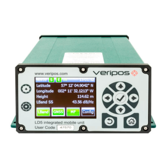
Page 14: Views And Controls
Navigation panel. Arrow keys are used to move through menu items and tick key (✓) is used to accept an item. Home Return User code (5 digits) Receiver card icons (3 max.) Rev No: Page 12 Date: 16.11.2018 LD5 (C Variant) Operation Manual... - Page 15 USB type B connector ** Grounding point DC power connector (12–24 VDC) *Standard (non-mod) LD5. Function of connector will differ on Mod LD5’s. ** Do not connect devices to LD5 without first performing a virus scan! Rev No: Page 13 Date: 16.11.2018...
-
Page 16: Ld5 Start Up
9. Access to configuration controls The Home screen of the LD5 screen displays the Unit user code number (1), ‘Sync’ (2) and ‘Enabled’ (3) indicators (Green = OK, Red = No sync / Disabled respectively). The L-Band signal strength indicator (4), has three states: No. -
Page 17: L-Band Receiver
L-Band > Status > Device Status s view allows the user to review the status of SNR, Beam, Frame Sync, Signal Lock and whether the LD5 is enabled or not To view the L-Band signal status, from the Home screen select L-Band > Status >... -
Page 18: L-Band > Config > Beam Selection
ANT connection at the rear of the LD5. When using a VERIPOS supplied antenna, the antenna voltage should normally be On, as the antenna requires power to operate. However, when the LD5 is connected to a vessel tracking dish such as a Fleet system, the voltage may be turned Off. -
Page 19: L-Band > Access Info
2.5.6 L-Band > Access Info If the LD5 has beam sync and is enabled the Home screen “E” symbol will appear as green. If the unit has sync but the unit is disabled, navigate to Home > L-Band > Access Info to view your LD5 Access Information: The unit “Enabled”... -
Page 20: Gnss Receiver
GNSS Receiver The LD5 GNSS card, status information and configuration settings are accessed from the Home screen. 2.6.1 GNSS > Status > Module Info This screen shows the firmware installed on the GNSS receiver. From the Home screen select GNSS > Status > Module Info. -
Page 21: Gnss > Status > Sv Info
2.6.2 GNSS > Status > SV Info This screen shows the number of satellites tracked by the LD5. From the Home screen select GNSS > Status > SV Info. The number of satellites tracked should not be confused with the number of satellites used. -
Page 22: Gnss > Status > Position Info
The Height displayed is WGS84 ellipsoidal height, not the antenna height above MSL. The GNSS heading displayed here will include any correction value which has been entered via GNSS > Config > Heading C-O. Rev No: Page 20 Date: 16.11.2018 LD5 (C Variant) Operation Manual... -
Page 23: Gnss > Status > Dop Values
GNSS > Status > Masks This screen shows the Mask value set on the GNSS receiver. The Mask value is setup automatically by the LD5 unit and cannot be set by the end user. From the Home screen select GNSS > Status > Masks. -
Page 24: Gnss > Config
2.6.8 GNSS > Config > PPP Config The PPP Config setting is used to determine which PPP solution the LD5 will produce. Changing the PPP Config settings will re-initialise a new PPP calculation, which will take time to settle and a PPP position output to be available. -
Page 25: Gnss > Config > Sbas
VERIPOS solution fail. For LD5-C3 variants, an MF solution will be output (if enabled) in the event of loss of the VERIPOS solution. An SBAS solution will therefore only be used if both VERIPOS and MF solutions are unavailable. -
Page 26: Gnss > Config > Nmea > Nmeaa (Or) Nmeab
* Select from 5 to 8 digit Lat / Long precision at GNSS > Config > NMEA Config. ** UKOOA can only be selected if all other NMEA messages are set to Off. *** Available on LD5 HDT licensed hardware. Rev No:... -
Page 27: Gnss > Config > Nmea > Config
2.6.12 GNSS > Config > Channel Config This menu is used for selecting between the tracking of Galileo or Beidou (Galileo is selected by default). Use the arrow keys switch between constellations: Rev No: Page 25 Date: 16.11.2018 LD5 (C Variant) Operation Manual... -
Page 28: Gnss > Config > Heading C-O
Navigate to Apply to confirm the change of constellation. 2.6.13 GNSS > Config > Heading C-O menu is only displayed on LD5’s which have the GNSS heading feature This enabled. For information on how to enable an LD5-C for GNSS heading, please refer section LD5 GNSS Heading. -
Page 29: Gnss > Help
If a heading offset has been entered in the receiving system (e.g. vessel DP), do not also enter an offset within the LD5. 2.6.13 GNSS > Help This screen shows VERIPOS website details, where product support and manuals are available. Rev No:... -
Page 30: Mf Beacon (Iala) Receiver
MF Beacon (IALA) Receiver The LD5 MF card, status information and configuration settings are accessed from the Home screen. 2.7.1 MF > Status > Module Info This menu displays details of the MF receiver card fitted, such as model and firmware version. -
Page 31: Mf > Config > Manual Tune
This setting requires the user to enter a frequency and data rate from Manual Tune Menu or select a station from the Station Tune Menu. VERIPOS recommend use of Automatic. Highlight the mode (press tick and then up / down arrows) then navigate to Apply and Select (✓). -
Page 32: Mf > Config > Station Tune
This menu allows the user to turn on or turn off the Antenna Voltage on the MF antenna connector on the rear of the LD5 unit. 2.7.7 MF > Help This screen shows VERIPOS website details, where product support and manuals are available. Rev No: Page 30 Date: 16.11.2018... -
Page 33: Ld5 Config
LD5 Config This menu allows access to the configuration of the LD5 unit. Configuration of serial ports and network settings are available in this menu. Access from Home > Config. 2.8.1 Config > I/O This page allows the user to select the pages required to configure the data outputs and inputs. - Page 34 Configure the Protocol, Baud Rate, Data Bits, Parity and Stop Bits: Use Left / Right arrow buttons to move between the 2 pages. Then navigate to Apply and select (✓) to finish the configuration. Rev No: Page 32 Date: 16.11.2018 LD5 (C Variant) Operation Manual...
-
Page 35: Config > I/O > Com X > Ext Rtcm
VERIPOS) RTCM corrections can be input via Ext RTCM. 2.8.4 Config > I/O > Network This menu allows the user to view or configure the Ethernet settings of the LD5 unit. From the Home screen select Config > Network To change the network settings select (✓) Select from DHCP or Static mode and if required amend the IP address, subnet mask and gateway using the control panel, then select Apply. -
Page 36: Config > Reboot
2.8.7 Config > Config This menu allows the user to view the Operating Mode of the LD5, change day / night screen settings and view the LD5 software version number and LD5 unit variant. The second page allows for adjusting the screen dimmer delay period (mins). -
Page 37: Ld5 Gnss Heading
2.9 LD5 GNSS Heading LD5-C variants are fitted with dual antenna input GNSS cards, which can be used to provide a GNSS heading solution. The GNSS heading function must be enabled before it can be used. Refer to Section Enabling the GNSS Heading Feature for guidance on enabling. -
Page 38: Enabling The Gnss Heading Feature
Unless requested at time of purchase, the GNSS heading feature is disabled by default. If you would like to use the GNSS heading feature, you will need to contact the VERIPOS Helpdesk to obtain a licence code. This licence code can be entered within the Admin Mode. -
Page 39: Veripos Software Compatibility
The LD5-C can be used with the VERIPOS visualisation software Quantum. Quantum is suitable for both DP and Survey applications. The LD5-C is NOT compatible with legacy software such as Orion and Verify QC. For further information regarding the new Quantum visualisation software, please visit VOSS at https://help.veripos.com... -
Page 40: Troubleshooting
4 Troubleshooting Overview of troubleshooting The LD5 uses a colour screen and navigation panel to access an embedded Windows The system contains no user-serviceable parts. The cover should not be removed except under the guidance of a VERIPOS engineer, first ensuring that the unit is isolated from all AC and DC power supplies. -
Page 41: Enable/Disable Faults
Check which beam is selected at new work region - beam L-Band > Status > Device Status. used has not been changed. If necessary, consult the Coverage chart at https://help.veripos.com Rev No: Page 39 Date: 16.11.2018 LD5 (C Variant) Operation Manual... - Page 42 If possible shut down possible sources to eliminate them. Antenna Visually check antenna and cable for DC disconnected or power and damage. Check coaxial inoperative. connections and inspect antenna for damage. Rev No: Page 40 Date: 16.11.2018 LD5 (C Variant) Operation Manual...
-
Page 43: Gnss Signal Faults
Aux GNSS power and damage. Check coaxial antenna. connections and inspect antenna for damage. Confirm there are no potential sources of interference or physical obstructions around the Aux GNSS antenna. Rev No: Page 41 Date: 16.11.2018 LD5 (C Variant) Operation Manual... - Page 44 Fault Reason Remedy No GNSS reception Check the LD5 Home screen to check if a from Main GNSS valid position is being displayed. No position antenna. indicates a problem with the Main GNSS feed. Visually check antenna and cable for DC power and damage.
-
Page 45: Veripos Helpdesk
Full vessel name correct identification is important; VERIPOS may have installation drawings. • Name of parent company • User Code (on front panel) and current ‘Access code’ of LD5, see the operation chapter for details. • Current status of the LD5 •... -
Page 46: Reference Information
(SAL). This takes the form of a contract which is agreed between the user's company and the VERIPOS Operations department. The equipment cannot be used until an enable code is obtained from the VERIPOS Helpdesk. The Helpdesk is not authorised to issue a code unless an active SAL exists and its number can be determined. -
Page 47: Global Coverage Chart
Global coverage chart Rev No: Page 45 Date: 16.11.2018 LD5 (C Variant) Operation Manual... -
Page 48: Com Ports
Default configuration for each COM port is: • 8 data bits • No parity • 1 stop bit This information may be required when interfacing to ships systems using RS-232/422 standards. The LD5 is the transmitting device. Function RS-232 RS-422 Not connected... -
Page 49: Ld5 Menu Structure
LD5 Menu structure Rev No: Page 47 Date: 16.11.2018 LD5 (C Variant) Operation Manual... - Page 50 L-Band Menu Structure of the LD5 GNSS Menu Structure of the LD5 Rev No: Page 48 Date: 16.11.2018 LD5 (C Variant) Operation Manual...
- Page 51 MF Menu Structure of the LD5 Rev No: Page 49 Date: 16.11.2018 LD5 (C Variant) Operation Manual...
- Page 52 Config Menu Structure of the LD5 Rev No: Page 50 Date: 16.11.2018 LD5 (C Variant) Operation Manual...
-
Page 53: Nmea Sentences
NOTE: The number of decimal places in the Latitude and Longitude values is configurable via the LD5 in the GNSS/ Config/ NMEA Config under NMEA Precision. Between 5 and 8 decimal places are selectable. - Page 54 UTC time in hours, minutes, seconds of the GPS position dd,mm,yyy Day,Month,Year (UTC) local zone hours (00 to +/-13 hrs) local zone minutes (00 to 59) *hh<CR><LF> checksum, carriage return and line feed Rev No: Page 52 Date: 16.11.2018 LD5 (C Variant) Operation Manual...
- Page 55 GLONASS constellation of 24 satellites, this gives a range of 65 through 88. The numbers 89 through 96 are available if slot numbers above 24 are allocated to on- orbit spares. Rev No: Page 53 Date: 16.11.2018 LD5 (C Variant) Operation Manual...
- Page 56 GLONASS constellation of 24 satellites, this gives a range of 65 through 88. The numbers 89 through 96 are available if slot numbers above 24 are allocated to on-orbit spares. Rev No: Page 54 Date: 16.11.2018 LD5 (C Variant) Operation Manual...
- Page 57 Note that, as of the 2.3 release of NMEA, there is a new field in the VTG sentence at the end just prior to the checksum. Receivers that don't have a magnetic deviation (variation) table built in will null out the Magnetic track made good. Rev No: Page 55 Date: 16.11.2018 LD5 (C Variant) Operation Manual...
- Page 58 3) When multiple GRS sentences are being sent then their order of transmission must match the order of corresponding GSA sentences. Listeners shall keep track of pairs of GSA and GRS sentences and discard data if pairs are incomplete. Rev No: Page 56 Date: 16.11.2018 LD5 (C Variant) Operation Manual...
- Page 59 $GPHDT – is the message name stating it is a GPS heading (true) message xxx.xx – this is the heading T – states the heading is true *hh – is the check sum for the message Rev No: Page 57 Date: 16.11.2018 LD5 (C Variant) Operation Manual...
- Page 60 Orientation Of Semi 172…177 F6.1 º See comment 10 Major Axis of Error Test (P=Pass, 178…179 See comment 11 F=Fail) No of Satellites used in 180…182 the Fix (n) Rev No: Page 58 Date: 16.11.2018 LD5 (C Variant) Operation Manual...
- Page 61 WGS84 reference ellipsoid, based on a Geoid model as for example EGM96. Fix Status Codes shows the calculation used, as different calculations can be labelled: 1, 2, 3 etc. Rev No: Page 59 Date: 16.11.2018 LD5 (C Variant) Operation Manual...
- Page 62 Orientation of the semi major axis (degrees from true North) A test applied to the Unit Variance. A “Fail” may result from F Test large outliers in the measurements. Rev No: Page 60 Date: 16.11.2018 LD5 (C Variant) Operation Manual...
-
Page 63: Contact Information
+44 (0)1224 965900 Helpdesk e-mail helpdesk@veripos.com VERIPOS Online support https://help.veripos.com If shipping equipment back to VERIPOS, please contact the Helpdesk who will provide the current shipping address, according to the user’s area of operations. VERIPOS Office Locations 6.2.1 VERIPOS UK...
Need help?
Do you have a question about the LD5 and is the answer not in the manual?
Questions and answers