Komfovent C6.1 Installation And Operation Manual
Hide thumbs
Also See for C6.1:
- Installation and operation manual (200 pages) ,
- Electrical installation and operation manual (28 pages)
Table of Contents
Advertisement
Advertisement
Table of Contents

Related Manuals for Komfovent C6.1


Summary of Contents for Komfovent C6.1
- Page 1 C6.1 C6.2 Electrical installation and Operation Manual...
-
Page 3: Table Of Contents
2.1. Unit control with the control panel ......................6 2.2. Unit operation via a web browser ....................... 7 2.3. Unit control with a smartphone ........................8 2.4. Control Panel C6.1 ............................. 8 2.4.1. Displayed symbols on the panel ...................... 9 2.4.2. Review of the parameters ........................ 9 2.4.3. -
Page 4: Electrical Installation Instructions
1. ELECTRICAL INSTALLATION INSTRUCTIONS The installation can only be performed by qualified personnel. It is necessary to follow the requirements below during the installation. It is recommended to lay the control cables separately from the power cables, at a minimum distance of 20 cm. The connector connection is performed strictly according to the wiring diagram numbering, or with adequate markings (see the principal wiring diagram of the unit). -
Page 5: Connection Of External Elements
1.3. Connection of external elements The air handling unit has external connection terminals in the control box, inside the air handling unit. They are used to connect all the external control elements. 1. Ethernet connection of computer network or Internet 2. -
Page 6: Temperature Sensor Installation
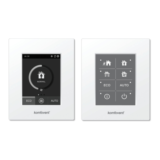
The air handling unit can be operated by one of the following panels (Fig. 2.1). C6.1 – panel with a touch screen for parameters of air handling unit setting and indication. The panel has inte- grated thermometer and hygrometer for indoor climate monitoring. -
Page 7: Unit Operation Via A Web Browser
2.2. Unit operation via a web browser Not only the control panel, but also a computer can be used to monitor the operation of unit and its components, as well as changing the settings and activating additional functions. You only have to connect the unit separate with the network cable, to a computer, local network or Internet. -
Page 8: Unit Control With A Smartphone
(described in more detail in the “Mobile applet installation instructions”). To download the applet, scan the necessary link, or just search for it in the GooglePlay or iTunes stores. Tip: The applet user interface and the control capabilities are fully consistent with the C6.1 control. 2.4. Control Panel C6.1... -
Page 9: Displayed Symbols On The Panel
2.4.1. Displayed symbols on the panel ECO mode on . Free heating Fan operation operation. Alarm signal Energy recovery operation (see the troubleshooting section) Air heater operation Supply air Air cooler operation Exhaust air There is a heating demand, but it is Outside air temperature being blocked by the ECO mode There is a cooling demand, but it is... -
Page 10: Operation Mode Selection
2.4.3. Operation mode selection There is provided four usual operation and four special operation modes. User can choose one of them from the main panel window by clicking on the center button. Operation modes AWAY NORMAL INTENSIVE BOOST KICHEN FIREPLACE OVERRIDE HOLIDAYS Usual operation modes... -
Page 11: Eco Mode
The parameters for all eight modes are preset at the factory, but each of them can be modified individually. This requires selecting the desired mode and touching the icon for five seconds. In the window that opens, you can change the air flow, temperature and deactivate the electric heater in the unit: NORMAL Supply flow 250 m... -
Page 12: Menu
2.4.6. Menu The settings menu consists of four points, where Menu Menu you can view the relevant user information, choose the operating schedule, change the set- Overview Overview tings or turn off the unit. If to the air handling unit is connected the air quality or humidity sensor, then the “Scheduling”... -
Page 13: Scheduling
Energy counters. This menu shows how much en- Alarms. This menu displays messages about exist- ergy is recovered by the heat exchanger, as well as ing faults. After the removal of the fault (see Chapter the energy consumed by the heater and the entire 2.6), these messages can be deleted by selecting unit. -
Page 14: Air Quality
Factory set schedules STAY AT HOME Program No. Days of the week Event start time Event end time Mode 00:00 08:00 AWAY Mo - Su 08:00 22:00 NORMAL 22:00 24:00 AWAY WORKING WEEK Program No. Days of the week Event start time Event end time Mode 00:00... -
Page 15: Settings
In the “Air Quality” settings menu item, the user can set the maintained air Air quality quality or humidity value, as well as the maintained temperature, and can de- activate the electric heater in the unit, if necessary. Air quality 800 ppm Air humidity Air temperature... - Page 16 This function requires additional VAV sensors, which must be ordered sepa- rately. The connection of the sensor is shown in Fig. 1.3b. If you select the VAV flow regime, the automatic air quality support will be disabled. The AUTO button will activate the weekly operation schedule. •...
-
Page 17: Control Panel C6.2
Connectivity. Upon connecting the unit via a web browser, you must configure Connectivity the computer’s network settings: IP address and subnet mask. IP address 192.168.0.60 Subnet mask 255.255.255.0 2.5. Control Panel C6.2 2.5.1 2.5.2 2.5.3 2.5.4 2.5.6 2.5.5 Fig. 2.5. C6.2 panel view 2.5.1. -
Page 18: Eco
2.5.2. „ECO“ An energy-saving mode to minimize the power consumption of the air handling unit. See more details in Sec- tion 2.4.4.. 2.5.3. AUTO mode AUTO – automatic operation mode when the unit is operating and changing ventilation intensity based on the chosen (pre-set) weekly operating schedule (for more details, see Section 2.4.6.2). - Page 19 Table 2.6.1. Alarms displayed in the C6.1 control panel, their possible causes and elimination methods Code Notification Possible cause Elimination Low supply air flow Too high resistance of the ventila- Check the air valves, air filters or tion system ventilation system for clogging.
- Page 20 ИООО «Комфовент» Республика Беларусь, 220125 г. Минск, ул. Уручская 21 – 423 Тел. +375 17 266 5297, 266 6327 minsk@komfovent.by www.komfovent.by Komfovent AB Ögärdesvägen 12B 433 30 Partille, Sverige Phone +46 31 487752 info_se@komfovent.com www.komfovent.se Komfovent GmbH Konrad-Zuse-Str. 2a, 42551 Velbert, Deutschland Mob.
Need help?
Do you have a question about the C6.1 and is the answer not in the manual?
Questions and answers