Table of Contents
Advertisement
Quick Links
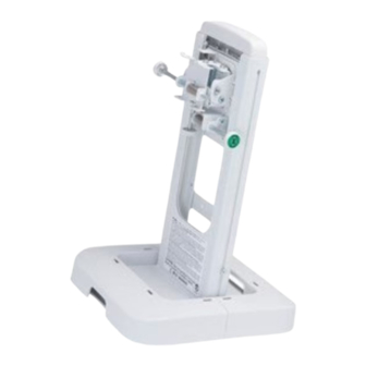
Wall mount unit for LCD projectors
HAS-WM05
Model name
Thank you for purchasing a wall mount unit specially designed for Hitachi LCD projectors.
Be sure to read this manual and the User's Manual supplied with the LCD projector before use so you will know
how to install it properly. After you have finished reading these documents, put them away in a safe place for future
reference.
● The content of this manual and the specifications of the product it describes are subject to
change without prior notice.
Disclaimer
● Note that Hitachi will accept no liability whatsoever for injuries and damages arising from
incorrect use or handling that exceeds normal operating limits.
Table of Contents
Disclaimer ................................................ 1
Table of Contents ..................................... 1
Safety Symbols ........................................ 1
Overview ................................................... 2
Installation Precautions .......................... 2
Tools needed for installation .................. 2
To the customer ....................................... 3
To service personnel ............................... 3
Routine Inspections ................................ 3
Contents of this package ........................ 4
Base bracket attachment diagram ......... 5
Template sheet usage .............................. 6
Installation procedure ............................. 7
1 Wall mounting of the base assembly ....... 7
2 Extending the arm bracket (IN) ................ 8
3 Attaching Adjusting block (D) .................. 8
screw (L) of the arm ............................. 9
Safety Symbols
The following symbols are used in this manual to help you use this product safely and correctly, and to prevent injury
to yourself and others or damage to property. Read through the safety instructions below so you can operate the
product correctly.
This symbol indicates information that, if ignored, could result in serious personal injury
WARNING
or even death due to incorrect handling.
This symbol indicates information that, if ignored, could result in personal injury or
CAUTION
physical damage due to incorrect handling.
Indicates a prohibited action.
This symbol is accompanied by text indicating an action that must not be taken.
Indicates a mandatory action.
This symbol is accompanied by text indicating an action that must be taken.
HAS-WM05
5 Mounting of the arm assembly (A) ........... 9
8 Removal and storage of screws .............11
9 Attaching bracket (F) ...............................11
0 Attaching LCD projector ..........................12
! Connecting cables ...................................12
Adjustments ............................................13
adjustments .........................................13
# Image adjustments ..................................14
Installing exterior parts ..........................17
% Attaching the cable cover ........................18
Adjustment precautions .........................19
Adjustment specifications .................... 20
Applicable models ................................. 21
1
User's Manual
Advertisement
Table of Contents

Related Manuals for Hitachi HAS-WM05


Summary of Contents for Hitachi HAS-WM05
-
Page 1: Table Of Contents
● The content of this manual and the specifications of the product it describes are subject to change without prior notice. Disclaimer ● Note that Hitachi will accept no liability whatsoever for injuries and damages arising from incorrect use or handling that exceeds normal operating limits. Table of Contents Disclaimer .......... -
Page 2: Overview
HAS-WM05 Overview This product is designed to mount a Hitachi LCD projector on a wall. Installation Precautions Installation of this product requires special technical skills. Ask your dealer or service center (for details, see the User’s Manual supplied with the LCD projector) to handle the installation work. -
Page 3: To The Customer
To the customer ■ Do not attempt to install the projector yourself. Have your dealer or service center handle all installation work. Note that Hitachi will accept no liability whatsoever for accidents or injuries resulting from an incorrect installation or improper use. -
Page 4: Contents Of This Package
HAS-WM05 Contents of this package Check that the items listed in the table below are included in this package. If any are missing, please contact your dealer immediately. (The fasteners (screws, etc.) required for wall mounting are not supplied with the wall mount unit. -
Page 5: Base Bracket Attachment Diagram
HAS-WM05 Base bracket attachment diagram Note: nit. The wall hole center is 34.6 mm (1.36 inches) to the right of the screen center. Screen center Wall hole center 34.6 (1.36) Cable cover Screen center (*1) Screen thickness Unit: mm (inches) -
Page 6: Template Sheet Usage
HAS-WM05 Template sheet usage Determining location of wall holes Place the template sheet (P) where you want to project the image. 1 Vertical orientation: Align the top of the sheet with the upper edge of the image you want to project. -
Page 7: Installation Procedure
HAS-WM05 Installation procedure 1 Fasten the base bracket (center) (B) to the base brackets (side) (C) with the eight M4 x 8mm hex-head screws (J). Base bracket (sides) (C) Base bracket (center) (B) Base bracket (sides) (C) M4 × 8 hexagon head screws (J) (Eight places) ■... -
Page 8: Extending The Arm Bracket (In)
HAS-WM05 2 Loosen the fastening screw (in the location indicated by the arrow in the diagram below) and extend the arm bracket (IN). Attach the adjustment block (D) to the arm bracket (IN). Fastening screw Adjusting block (D) Arm bracket (IN) -
Page 9: Installation Of The Vertical Adjustment Screw (L) Of The Arm
HAS-WM05 4 Attach the M10 x 162mm arm vertical adjustment screws (L) to the base bracket assembly (A) up to the red mark. Arm assembly (A) Red mark Red mark M10 x 152mm Arm vertical adjustment screw (L) 5 Mount the arm assembly (A) on the base bracket assembly. - Page 10 HAS-WM05 6 Pass the M10 x 194mm arm fixing strut screws (K) from under the base bracket (center) (B) and tighten them with a hex wrench (O) and fasten the arm assembly (A). (Two places) M10 x 194mm Arm fixing strut screw (K)
-
Page 11: Installation Of The Arm Fixing Strut Screw (K) .10 7 Installation Of The Strut Cover Bracket (M) .10 8 Removal And Storage Of Screws
HAS-WM05 8 Remove the temporary mounting screws, and attach them to the base bracket (B) for storage. Remove the temporary screws (Two places). Attach to base bracket (B). 9 Attach the bracket (E) to the LCD projector using four M4 × 8 (J) hexagon head screws. -
Page 12: Attaching Lcd Projector
HAS-WM05 0 Mount bracket (E) from the direction of the arrow to the adjustment block (D). Tighten the three M5 x 8mm shoulder screws (N) and one M4 x 8mm hex-head screw (J). Tightening torque: 0.98 N•m (10 kgf•cm) Adjusting block (D) -
Page 13: Adjustments
VOLUME MAGNIFY 4 Use the cursor buttons (▲/▼) to select + SCREEN. DOWN ー 5 Use the cursor buttons (▲/▼) to select HAS-WM05 in the illustrated template. KEYSTONE MY BUTTON MUTE TEMPLATE Press the ENTER button to display the selected... -
Page 14: Image Adjustments
HAS-WM05 # Adjust the image. #-1. Adjustment of image size. 1. Slide the arm forward and backward to adjust image size. Scale 1. F 2. F Adjustment screw, center Adjustment screw (hex-head screw) 3. F Align the center of the adjustment screw (hex-head screw) to the scale to adjust for the required screen size. - Page 15 HAS-WM05 #-2. Make a rough focus adjustment. For details, see the User’s Manual for the LCD projector. #-3. Make fine adjustments. Loosen fastening screws (1) to (4). Follow the steps below to turn the adjusting screws and adjusting knobs to adjust the image.
- Page 16 HAS-WM05 7. Fine adjustment of vertical position Turn the height adjusting screw to adjust the height. Supplied Allen wrench (O) • Repeat steps 1 to 7 to fine adjust the image to the screen. See page 20 for details on adjustment range.
-
Page 17: Installing Exterior Parts
HAS-WM05 Installing exterior parts $ Procedure for installing exterior parts $-1. Attach the front cap (F) at the front end of the Arm bracket (IN). Hook the tabs on either side in the holes in the arm bracket (IN). Front cap (F) Hole Attach the cable cover. -
Page 18: Attaching The Cable Cover
HAS-WM05 % Attaching the cable cover %-1. Fasten the cable cover (G) with the two M4 x 8mm hex-head screws (J). • • • • • Cable cover (G) • M4 × 8 hexagon head screws (J) (Two places) %-2. Attach cable cover (I) first. -
Page 19: Adjustment Precautions
HAS-WM05 Adjustment precautions • Roll down screens and other screens that are not perfectly flat tend to substantially distort the projection surface and cannot be used. Use board screens or other flat screens. Bead-type screens with a high screen gain are not suitable for this projector. Use of a matte screen with a wide viewing angle and a gain of about 1.0 is recommended. -
Page 20: Adjustment Specifications
HAS-WM05 Adjustment specifications Fine adjustment amount Description of Item Image movement (amount of LCD projector movement) adjustment method Fine adjustment of ±5° page 15 horizontal position Fine adjustment of ±5° page 15 horizontal keystone Fine adjustment of ±5° page 15... -
Page 21: Applicable Models
HAS-WM05 Applicable models Supported Hitachi LCD projector models Model Screen size Weight LCD projector CP-AX2503 Approx. 4.2kg model A CP-AX3003 CP-AX3503 CP-AW2503 CP-AW3003 16:10 CP-TW2503 CP-TW3003 Wall mount unit HAS-WM05 Approx. 6.4kg...
Need help?
Do you have a question about the HAS-WM05 and is the answer not in the manual?
Questions and answers