
Related Manuals for Tempo Fitness Sidekick 7B

Summary of Contents for Tempo Fitness Sidekick 7B
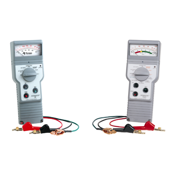
- Page 1 Tempo ® Sidekick 7B and T&N Training Course Revision 1.03 7B Model T&N Model This manual is for training purposes only.
- Page 2 PREAMBLE “Never could a highly trained and experienced technician place more emphasis paramount thorough understanding of the following principles and analytical procedures are to “Finding a better way” to trouble shoot outside plant and equipment…” Rev. 11/10/00...
-
Page 3: Table Of Contents
Crosses ..............................6 Splits..............................6 Power Influence ........................... 6 Induction .............................. 6 Circuit Loss ............................6 Loop Current............................6 SIDEKICK 7B .............................. 7 General Description..........................7 Features ............................... 7 Benefits..............................8 Front Panel Controls ..............................8 AC Volts Test ................................9 DC Volts Test ................................ - Page 4 QUIZ 2................................. 19 Leakage Test ............................21 Resistance Test ................................. 22 Resistance/Conductor Length (Approximate) ..................22 Capacitive Kick................................. 23 Kickmeter ............................23 To Kick a Pair ............................ 23 Capacitance/Conductor Length (Approximate) ................. 23 QUIZ 3................................. 25 EXAM 1............................... 27 SIDEKICK T&N ............................30 Features .............................
-
Page 5: A Brief History Of Tempo Research Corporation
A Brief History of Tempo Research Corporation In August 1984, a small San Diego based company, Tempo Research Corporation, began designing, developing, manufacturing, and marketing copper cable fault locators for the telecommunications industry. As time progressed, it became evident that fiber optics would replace copper wire. - Page 6 Sidekick was used. After approximately forty-five hundred of these were produced, the next generation of Sidekicks began to arrive – the Sidekick 7B. The Sidekick 7B In 1993, the Sidekick received a complete face lift and some ergonomic improvements based on recommendations from the field.
- Page 7 The Sidekick 7B “Big Head” The Sidekick 7B “Big Head” made it’s appearance in 1996, and because of their popularity, toggle switches became the standard. Currently used throughout the telephone industry, the Sidekick 7B embraces unparalleled competition as the technicians “Test set of choice”. It is used by every major telecommunication company in the United States as well as numerous countries around the globe.
-
Page 8: Mastering The Fundamentals
Mastering The Fundamentals BASIC ELECTRONICS This section provides an overview of basic electronics and the theory associated with outside plant telephone circuitry. Those not familiar with electronics should review this material for a basic understanding of how the various electrical characteristics in a circuit interact. It is important to know that each twisted pair of copper wires in a telephone cable forms a circuit. -
Page 9: Current
Current Current is the rate of flow of electricity through a circuit. In simple terms, it is the number of electrons that flow past a specified point in one second of time. Current is measured in amperes using the letter A in the measurement and the letter I in formulas. -
Page 10: Capacitive Reactance
Capacitive Reactance Basically, reactance is to an AC circuit what resistance is to a DC circuit. Reactance, however, is affected by the value of the component and the frequency of the circuit in which it is being used. Capacitive reactance, commonly expressed as Xc, is inversely proportional to the value of the capacitor and the frequency. -
Page 11: Power Formulas
Power Formulas Like Ohms law, power formulas use several variants of a formula to calculate power. Voltage, current, and resistance can be used to calculated power when two of these three values are known. Power, in electrical terms, is expressed as Watts using the letter W as its symbol in measurements and the letter P in formulas. -
Page 12: Opens
There are several types of electrical faults. The most common are opens, shorts and grounds. Other common telephony faults include resistance faults, noise, line imbalance, crosses, splits, power influence, induction, circuit loss, and low loop current. Multiple faults can occur simultaneously. Each of these fault types are discussed in the following paragraphs. -
Page 13: Crosses
Crosses A cross occurs whenever a Tip or Ring conductor of one pair touches a Tip or Ring conductor of another pair. A battery cross occurs when a Tip or Ring conductor in a pair touches another Ring conductor. Splits Splits occur when the Tip or Ring conductor of one pair is transposed with the Tip or Ring conductor of another pair. -
Page 14: Sidekick 7B
SideKick 7B General Description The Sidekick 7B is the test set used by every major telephone company in the United States to troubleshoot twisted pair applications. This lightweight, hand- held meter quickly and accurately uncovers intermittent troubles that other test sets cannot detect. -
Page 15: Benefits
Benefits • Improves customer satisfaction • Reduces repeat service calls • Eliminates service interruptions • Works on any twisted pair application • Increases service productivity • Provides quick return on investment Front Panel Controls Mode Switch: Selects the following functions: Off - Powers the Sidekick off. -
Page 16: Ac Volts Test
, you should check for AC and BEFORE YOU START ANY FAULT TESTING DC voltage. It’s rare to find AC on a POTS line, but it does happen. check for you check for ALWAYS AC BEFORE AC Volts Test The AC Volts function tests for the presence of AC voltage on the pair. To check for AC volts, 1. -
Page 17: Quiz 1
Quiz 1 1. The red scale on the Sidekick 7B meter is used to read AC or DC voltages. 2. The DC Volts test can be used to indicate: a) CO battery presence b) battery cross on vacant pairs c) both A and B above d) none of the above 3. - Page 18 9. To detect battery on the Tip wire: a) use the AC Volts test and toggle the switch to the position. DOWN b) use the DC Volts test and hold the Tip switch c) use the AC Volts test and hold the Tip switch d) use the AC Volts test and hold the Ring switch 10.
-
Page 19: Stress Test
Stress Test When the Stress test is initiated, the Sidekick stresses the pair with a 90 dBrnC longitudinal signal. This signal drives current through any series resistance fault on the pair. The series resistance converts the longitudinal current into Metallic Voltage at the fault which produces the high Stressed Noise. -
Page 20: Procedure
To verify good ground: 1. Turn the to the position. MODE SWITCH 2. Connect test leads; Black, Red, and Green to; Tip, Ring, and Ground. 3. Turn the MODE SWITCH STRESS TEST 4. Remove either the test lead. RING The ground is good if 70 dBrnC or higher is displayed. Lower readings may indicate a defective Ground or Short Loop. - Page 21 When performing the Stress test on complete end-to-end circuits, use the following Stress Test Evaluation Scales to determine pair quality. FEET FEET The following Noise Metallic readings, as a general rule, may be used as a guide to determine pair quality. Stress Test: Measured in dBrnC Scale:...
-
Page 22: Bridged Stressed Noise Readings
These ranges assume that little or no additional influence is present on the pair from the C.O. or Remote Terminal Units. Refer to the graphs and notes in the Sidekick’s Operating Manual Appendixes for expected results. Use the following testing tips if readings greater than 30 dBrnC are observed on Working-idle or On-hook working circuits: 1. -
Page 23: Stress Test Effectiveness
: Short and ground the pair at the far end. Using the Resistance test, measure each side to ground. The highest reading is the Series Fault. Stress Test Effectiveness The Stress test identifies capacitive imbalances (i.e., unequal conductor lengths) and DC problems (i.e., crosses and grounds) anywhere along the length of a Dry or Idle Working pair. -
Page 24: Testing Dssc, Daml, Or Udc Pair Gain Line
Testing DSSC, DAML, OR UDC Pair Gain Line , and pair gain lines carry approximately 70 to 130 VDC DSSC DAML between the Central Office Terminal (COT) and the Remote Terminal Unit (RTU) located at the subscriber end. These lines also exhibit Stressed Noise readings of 80 dBrnC and higher in the Stress test mode. - Page 25 1. Trouble in C.O. 2. Trouble in 3. Trouble in 4. Trouble Isolation in 5. Trouble (Hi- Resistance Open) in Drop 6. Trouble in F2: Beyond Sub. Rev. 11/10/00...
-
Page 26: Quiz 2
Quiz 2 1. The Stress test identifies and isolates the following faults: a) high resistance or series opens b) split or crossed pairs c) unequal conductor lengths d) all of the above 2. When using the Stress test, the signal used to stress the pair is: a) a 90 dBrnC longitudinal signal b) a 90 dB noise metallic signal c) a complex tone to warn the customer of a test... - Page 27 8. An acceptable dBrnC reading in the Stress test would be in the range: a) 30-70 dBrnC b) 35-50 dBrnC c) 0-90 dBrnC d) 0-30 dBrnC 9. As the Sidekick gets closer to the fault, the readings on the meter when in the Stress test will: a) increase b) decrease...
-
Page 28: Leakage Test
Leakage and Resistance Leakage Test The Leakage test detects intermittent Resistance Faults that do not appear under normal tests. When pairs with Resistance Faults are vacant, galvanic action forms an insulating oxide layer over the faults leaving them undetectable to standard ohmmeters. -
Page 29: Resistance Test
Resistance Test The Resistance test measures the resistance level of a pair’s line(s) by placing low voltage on the test leads and reading the current flow from either the Tip-to- Ring, Tip-to-Ground, or Ring-to-Ground wire depending on the switch position. From Ohm’s Law, the resistance is calculated from the voltage and current. -
Page 30: Capacitive Kick
Capacitive Kick Kickmeter A conductor has capacitance to Ground or to other conductors within a cable proportional to its length. In the RX1K and RX10K modes, this capacitance is charged by the Sidekick’s battery. Changing the position (throw) of the Reverse switch not only reverses polarity, but creates a sudden capacitive discharge causing the meter’s needle to “Kick”. - Page 31 To determine the approximate length of a conductor, compare the pair’s kick reading to the Kickmeter Conversion Chart found in Appendix C of the Sidekick’s Operating Manual. If a pair is open on one side, only the shorter side will produce an accurate reading.
-
Page 32: Quiz 3
Quiz 3 1. The Leakage test can be used to detect intermittent resistance faults in a pair? 2. The Leakage test uses what voltage to “Punch through” the oxide layer? a) 10,000 Volts DC 135 Volts DC 90 Volts DC 135 Volts AC 3. - Page 33 8. The “Kick” in the meter reading is proportional to the conductor’s: a) height b) length c) depth d) gauge 9. When using the Sidekick as a “Kick” meter, which meter scale is used? a) black b) red 10. In the RX10K mode, each point on the scale represents approximately what distance when in the “Kick”...
-
Page 34: Exam 1
Exam 1 1. The Sidekick 7B can be used to detect grounds. 2. When using the Sidekick as a kick meter, how many feet per point of “Kick” are shown in the RX1K scale? 5,000 d) 10,000 3. How many feet per point of “Kick” are shown when in the RX10K (Leakage) - Page 35 7. Which voltage range is considered good for a CO battery reading when testing Tip-to-Ring voltage? a) 48-52 Vac b) 70-90 Vdc c) 48-52 Vdc d) 0-100 Vdc 8. To test for CO battery presence, which of the following tests is used? a) DC Volts Test b) Stress Test c) AC Volts Test...
- Page 36 14. The Leakage (RX10K) mode can be used with CO battery on the line. 15. In the Stress test, an acceptable reading would be in the range of: 0-90 dBrnC b) 40-70 dBrnC c) 35-50 dBrnC 0-30 dBrnC 16. Which test is used to check for capacitive imbalance in a pair? a) Resistance test b) Leakage test c) Kick test...
-
Page 37: Sidekick T&N
SideKick T&N The Sidekick T&N combines the functions of the Sidekick 7B plus five new Transmission and Noise testing features. The result is a more versatile test set that identifies frequently missed faults and qualifies POTS line transmission quality. The new tests are: Loop Current; Circuit Loss; Metallic Noise; Power Influence;... - Page 38 Stress Test - Measures the audible noise produced while stressing a pair with a balanced longitudinal signal approximating a 90 dBrnC Power Influence; read-out is in decibels above reference noise, C-message weighted (dBrnC) on the meter’s black scale. Leakage (RX10K) - Ohms circuit that applies 135 VDC to a pair to reveal Resistance Faults masked by galvanic corrosion;...
-
Page 39: Coil Detect Test
Coil Detect Test The Sidekick T&N can detect up to four (4) load coils on a pair. However, three (3) or fewer load coils may be detected if problems exist on a pair. Example: If the trouble is on the end segment of a pair, the fourth load coil may not be detected. -
Page 40: Loop Current Test
8. If the needle swings to the right, then falls to a position slightly above 50; a load coil has been detected. a. The first coil detected is indicated by a large needle pulse. b. The second, third, and fourth coils are indicated by progressively smaller needle pulses. -
Page 41: Power Influence Test
Power Influence Test The Power Influence test specifically identifies Electro Magnetic Interference (EMI) from external sources (mainly power lines). When this test is initiated, a 600 Ohm resistance is placed across Tip and Ring which simultaneously measures Noise-to-Ground. Procedure 1. Turn the MODE SWITCH OFF/DIAL. -
Page 42: Circuit Loss Test
Procedure 1. Turn the MODE SWITCH OFF/DIAL. 2. Connect test leads; Black, Red, and Green to; Tip, Ring, and Ground. 3. Connect a telephone headset (buttset) to the base terminals on the Sidekick T&N. 4. Using the buttset, dial a quiet line termination. Once a connection is established, turn the The test set will hold MODE SWITCH... - Page 43 4. Using the buttset, dial the CO’s milliwatt (1004 Hz), or a frequency generator, test number. Once a connection is established, turn the MODE . The test set will hold the connection, however, the SWITCH CKT. LOSS buttset will disconnect from the circuit. 5.
-
Page 44: Quiz 4
Quiz 4 1. Unacceptable Circuit Loss would measure: a) 0 to -8.5dB (green zone on meter scale) b) -8.6 to -10dB (yellow zone on scale) c) below -10dB (red zone on meter) d) none of the above 2. The farther away the Sidekick T&N is from the test signal’s output, the less the Circuit Loss that is measured. - Page 45 8. The marginal Loop Current range would be: a) below 20 mA b) 20 – 23 mA c) 23 mA and higher d) None of the above 9. In the Load Coil test, a needle dip from the far right to about 50 indicates that a load coil was detected.
-
Page 46: Exam 2
Exam 2 1. The Circuit Loss test measures the signal attenuation on a line: a) from the CO to the point of test b) from the customer premise to the CO c) from the point of test to the customer premise d) from the point of test to the fault 2. - Page 47 8. An acceptable Loop Current test level would read: a) 23 to 30 mA b) 60 to 80 mA c) above 90 mA d) below 20 mA 9. Loop current is inversely proportional to resistance, therefore as resistance increases, the loop current measured on a pair: a) decreases b) increases c) remains constant...
-
Page 48: Quiz & Exam Answers
Quiz & Exam Answers Quiz 1 Quiz 2 Quiz 3 Quiz 4 Exam 1 Exam 2 1. False 1. D 1. True 1. C 1. True 1. A 2. B 2. True 2. C 2. A 2. B 2. False 3. -
Page 49: Trouble Shooting Inside Wiring
Trouble Shooting Inside Wiring Except for wire length considerations, Inside Wire Trouble Shooting is the same as Outside Plant. Because Inside Wire lengths are much shorter, various test values will differ significantly. Successful Fault Analysis is dependent upon the following tests and meter readings. Testing for Good Ground 1. -
Page 50: Resistance Testing - Toning The Fault
Resistance Testing – Toning the Fault 1. Tone the faulted Inside Wire with a Tone Generator to locate its corresponding phone jack. The fault will either be in the wire or in the jack – at the pins. 2. If the fault is in the jack, repair or replace. 3. -
Page 51: Cleaning And Maintenance
CLEANING AND MAINTENANCE To clean the Sidekick, simply wipe off any dirt or dust with a soft cloth. If necessary, lightly moisten the cloth to remove any smudges. If left inside the carry case, the Sidekick will require little care. Routine maintenance is limited to occasional battery replacement, periodic test lead cleaning, and test clip replacement. -
Page 52: Test Lead Replacement
Test Lead Replacement 1. Remove the battery compartment cover. 2. Using a #1 Phillips screw driver, remove the binding post set screws along with their upper flat and lock washer sets. 3. Remove the leads from the test lead channels by pulling them out through the bottom of the case. -
Page 53: Frequently Asked Questions
FREQUENTLY ASKED QUESTIONS What are the five most common uses for the Sidekick? • Checking for a correct battery or unwanted battery on twisted pairs. • Checking the longitudinal balance of twisted pairs. • Checking for insulation leakage on twisted pairs. •... - Page 54 Q. Can the Sidekick be used to check Hi-Cap (ISDN, T-1, DSL, etc.) service lines? A. Yes. However, unlike a POTS line, high-capacity lines MUST BE OUT OF before testing with a Sidekick. In most cases, Stress Test readings SERVICE below 20 dBrnC should be attainable.
- Page 55 Q. What is the difference between a Sidekick 7B and a Sidekick T&N? A. Physically, they are the same. Electronically, the Sidekick T&N has all the same tests as the 7B plus five transmission and noise tests: Circuit Loss, Circuit Noise, Power Influence, Loop Current, and Load Coil detection.
-
Page 56: Glossary
Glossary ampere 2400 baud rate The standard measurement unit of Modem speed of 2400 bits per electrical current flow. second. amperage 9600 baud rate The amount of electrical current flow. Modem speed of 9600 bits per second. amplification The process by which the output of a 14.4 kpbs circuit becomes an enlarged Modem speed of 14400 bits per... - Page 57 baud Caller ID on Call Waiting A unit of signaling speed equal to the A service feature that delivers calling number of signal events per second. number and/or calling name Baud is equivalent to bits per second information for an incoming Call in cases in which each signal event Waiting call.
- Page 58 weighted by a frequency function continuity test Verifies the integrity of an electrical called “C-Message weighting”. circuit. dc or DC converter Direct current, (dc) preferred. A device that changes alternating Electrical current that flows in one current to direct current and vice direction.
- Page 59 electrostatic induction fault tolerance The process of inducing static electric The capability of a system to charges on a body by bringing it near continue to operate in the event of a other bodies that carry high hardware or software failure. electrostatic charges.
- Page 60 vault to install, splice, or repair cables high speed data Data transmissions speeds at or above between conduit runs. 56 kbps. Mbps impedance Megabits per second. The total passive opposition to megabit alternating current flow. One million bits. inductance megabyte An electrical characteristic, measured in henrys that opposes any changes in One million bytes.
- Page 61 oscillation pulse TDR A periodic change in voltage, current, A Time Domain Reflectometer used or other quantity above or below a to identify and locate breaks in a mean value. transmission line. OTDR pulse width An Optical Time Domain The measured interval between the Reflectometer is designed and used 50 percent amplitude points of the for fiber optic line testing.
- Page 62 RS-232 splitter Now, EIA/TIA 232E. An electrical A circuit or device that distributes an and mechanical standard for digital input signal to several outputs. serial information transfers between step TDR computers, computer peripherals, or A Time Domain Reflectometer that communications equipment. provides ultra high resolution for broadband networks.
- Page 63 telecommunication wire center The transmission and reception of A local terminating point for audio, video, data, and other telephone wires, switches, and intelligence by wire, radio, light, and devices. other electronic or electromagnetic wire, line systems. Copper, copper steel, copper- aluminum or steel wire strung Time domain reflectometer.
Need help?
Do you have a question about the Sidekick 7B and is the answer not in the manual?
Questions and answers
Is there a chart that gives you breakdown on open distance using different cable gauge