Philips MCM118D Service Manual
Hide thumbs
Also See for MCM118D:
- Specifications (2 pages) ,
- Owner's manual (12 pages) ,
- Specifications (2 pages)
Advertisement
Quick Links
Download this manual
See also:
Owner's Manual
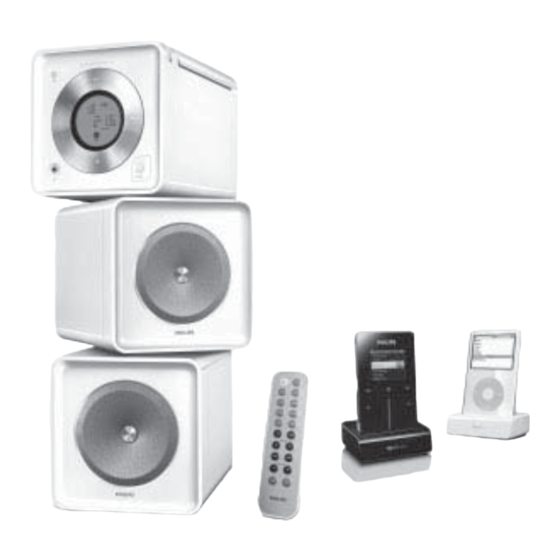
Micro Hi-Fi System
©
Copyright 2006 Philips Consumer Electronics B.V. Eindhoven, The Netherlands
All rights reserved. No part of this publication may be reproduced, stored in a retrieval system or
transmitted, in any form or by any means, electronic, mechanical, photocopying, or otherwise without
the prior permission of Philips.
Published by LX 0631- Service Audio
Version 1.0
TABLE OF CONTENTS
Handling chip components .......................................... 1-1
Technical Specifi cations .............................................. 2-1
Service Tool ................................................................. 2-1
Measurement setup ..................................................... 2-2
Connections and Controls ....................................3-1..3-2
Set Block diagram ....................................................... 4-1
Set Wiring diagram ...................................................... 4-2
Disassembly diagram .................................................. 5-1
Main board
Circuit diagram ..................................................6-1..6-2
Layout diagram ..................................................6-3..6-4
Display&Tuner board - Circuit diagram ................7-1..7-2
Display&Tuner board - Layout diagram ................7-3..7-4
AMP&Power board - Circuit diagram........................... 8-1
AMP&Power board - Layout diagram .......................... 8-2
Set Mechanical Exploded view ................................... 9-1
Mechanical Service parts list ...................................... 9-2
Electrical Service parts list..............................10-1 .. 10-4
Printed in The Netherlands
Page
Subject to modifi cation
MCM118D/
all
© 3141 785 31380
Advertisement

Related Manuals for Philips MCM118D


Summary of Contents for Philips MCM118D
-
Page 1: Table Of Contents
Electrical Service parts list......10-1 .. 10-4 © Copyright 2006 Philips Consumer Electronics B.V. Eindhoven, The Netherlands All rights reserved. No part of this publication may be reproduced, stored in a retrieval system or transmitted, in any form or by any means, electronic, mechanical, photocopying, or otherwise without the prior permission of Philips. - Page 2 1 - 1...
-
Page 3: Technical Specifi Cations
2 - 1 TECHNICAL SPECIFICATIONS... - Page 4 2 - 2...
-
Page 5: Connections And Controls
3 - 1 CONNECTION AND CONTROLS... - Page 6 3 - 2 CONNECTION AND CONTROLS...
-
Page 7: Set Block Diagram
4 - 1 SET BLOCK DIAGRAM... -
Page 8: Set Wiring Diagram
4 - 2 SET WIRING DIAGRAM... -
Page 9: Disassembly Diagram
5 - 1 5 - 1 DISASSEMBLY DIAGRAM Dismantling of the Bottom Cabinet 1) Remove 4 screws A as indicated to loosen the Rear Cabinet. 2) Remove 2 screws B as indicated to loosen the Bottom Cabinet. BOTTOM CAB. Dismantling of the Front Cabinet and Main Board 1) Remove 2 screws C as indicated to loosen the Front Cabinet. -
Page 10: Circuit Diagram
6 - 1 6 - 1 CIRCUIT DIAGRAM - MAIN BOARD CD PART... - Page 11 6 - 2 6 - 2 CIRCUIT DIAGRAM - MAIN BOARD AMP & POWER PART...
-
Page 12: Layout Diagram
6 - 3 6 - 3 LAYOUT DIAGRAM - MAIN BOARD COMPONENT SIDE... - Page 13 6 - 4 6 - 4 LAYOUT DIAGRAM - MAIN BOARD COPPER SIDE...
- Page 14 7 - 1 7 - 1 CIRCUIT DIAGRAM - DISPLAY&TUNER BOARD PART 1...
- Page 15 7 - 2 7 - 2 CIRCUIT DIAGRAM - DISPLAY&TUNER BOARD PART 2...
- Page 16 7 - 3 7 - 3 LAYOUT DIAGRAM - DISPLAY&TUNER BOARD COMPONENT SIDE...
- Page 17 7 - 4 7 - 4 LAYOUT DIAGRAM - DISPLAY&TUENR BOARD COPPER SIDE...
- Page 18 8 - 1 8 - 1 CIRCUIT DIAGRAM - AMP&POWER BOARD...
- Page 19 8 - 2 8 - 2 LAYOUT DIAGRAM - AMP&POWER BOARD...
- Page 20 9 - 1 9 - 1 SET EXPLODED VIEW DIAGRAM...
- Page 21 IPOD DOCKIN ASS'Y 9965 000 39794 HDD DOCKIN ASS'Y 9965 000 39795 REMOTE ASS'Y "PHILIPS" 9965 000 39796 SPK BOX ASS'Y (L/R) "PHILIPS" 9940 000 05378 AM LOOP ANT ASS'Y WH 9965 000 39797 USB/RCA CABLE 1M 9965 000 39798...
- Page 22 10 - 1 ELECTRICAL PARTSLIST - MAIN BOARD - IC & TRANSISTORS - 9965 000 39345 TRANSISTORS 2W 8050D 9965 000 39345 TRANSISTORS 2W 8050D 9965 000 39345 TRANSISTORS 2W 8050D 9965 000 39345 TRANSISTORS 2W 8050D 9965 000 38610 TRANSISTORS 2W 8550C 9940 000 01193 TRANSISTORS KSB772YS...
- Page 23 10 - 2 ELECTRICAL PARTSLIST - DISPLAY & TUNER BOARD - IC & TRANSISTORS - 9965 000 38610 TRANSISTORS 2W 8550C Q209 Q207 9965 000 39348 PNP TRANSISTORS 9012G 1W 9940 000 04143 NPN TRANSISTORS 9014C Q208 Q210 9940 000 04143 NPN TRANSISTORS 9014C Q211 9940 000 04143...
- Page 24 D110 9940 000 03938 RECTIFIER DIODE RL-202 D111 9940 000 03938 RECTIFIER DIODE RL-202 IC101 9965 000 39816 IC (PHILIPS) TFA9843BJ T102 9965 000 39817 TRANSFORMER EI28 Z11 120V/60HZ L101 9940 000 01226 AC LINE FILTER IND. 400UH 3A F101...
- Page 25 10 - 4 ELECTRICAL PARTSLIST - MISCELLANEOUS - 9940 000 03661 SPK JACK PT-22V11 9940 000 01942 16P FFC 1MM L80MM 9940 000 01255 15P FFC 1.25MM L=180MM 9965 000 39821 AC CORD CUL APP 6FT (M.T) 9965 000 39822 MAIN BOARD ASS'Y 9965 000 39823 POWER BD ASS'Y (37)
Need help?
Do you have a question about the MCM118D and is the answer not in the manual?
Questions and answers