Table of Contents
Advertisement
PIN NUMBER: 0558CP1695
Rev 4
FR850-V & FR850-NV
[With ANTOSS Remote]
TECHNICAL MANUAL & USER HANDBOOK
CE APPROVAL: BS EN509:2000+A1:2003+A2:2004
Serial Number ....................................
For use with Natural Gas (G20) or LPG (G31) – refer to dataplate
Important:
It is recommended, even if you have fitted these appliances
before, that you take the time to read through these instructions and follow
them step by step.
Please quote this serial number when calling to discuss installation and spare
part requests. The Warranty is valid for 1 Year from date of delivery.
To register the appliance complete the warranty card supplied and return to:
Spirit Fires Limited. 4 Beaumont Square, Aycliffe Industrial Park,
Newton Aycliffe, County Durham, DL5 6XN.
This manual must be handed to the owner of the property once the
appliance has been installed and commissioned
Page 1 of 54
Advertisement
Table of Contents

Related Manuals for Spirit Fires FR850-NV


Summary of Contents for Spirit Fires FR850-NV
- Page 1 The Warranty is valid for 1 Year from date of delivery. To register the appliance complete the warranty card supplied and return to: Spirit Fires Limited. 4 Beaumont Square, Aycliffe Industrial Park, Newton Aycliffe, County Durham, DL5 6XN.
-
Page 2: Table Of Contents
Contents Page 4 Technical Data Page 5 Description Page 5 Read This First Page 6 Unpacking the Appliance Page 6 Parts List Page 7 Construction Drawings Page 8 Gas Burner Construction Page 9 Remote Control System Page 10 Installation Requirements Page 12 Building &... - Page 3 Description of FR-850 Design This appliance is supplied as a complete suite of gas fire burner unit with remote control and enclosure, there is an optional gather. To comply with the approval this fire must be installed as designed. There are two versions which can be purchased by the customer depending on site specific conditions like chimney size and room ventilation.
-
Page 4: Technical Specification
Technical Specification Important Note: This fire is available in various designs, check delivery paperwork and the data plate on the fire to confirm which version has been purchased. MODEL FR-850-V FR-850-V FR-850-NV* Gas Type Natural Gas Gas Category Gas Type Inlet Pressure (mbar) Injector 145 x 1pc... -
Page 5: Read This First
Class 1 chimney at 2m in length. This version needs room ventilation with a 100cm2 air vent to the outside air. • FR850-NV – This version has a minimum flue size of 127mm diameter flue or Class 2 chimney at 3m in length. This version does not need room ventilation. -
Page 6: Parts List
Unpacking the Appliance Carefully examine the carton for damage before proceeding. If it is obviously damaged, please contact supplier to discuss whether to proceed. Please check your delivery note. Any missing parts must be notified within 48 hours of delivery and prior to installation. If the carton is undamaged remove the gas fire from the packaging and examine its general condition. - Page 7 Construction Dimensions FR-850-V FR-850-NV Page 7 of 54...
-
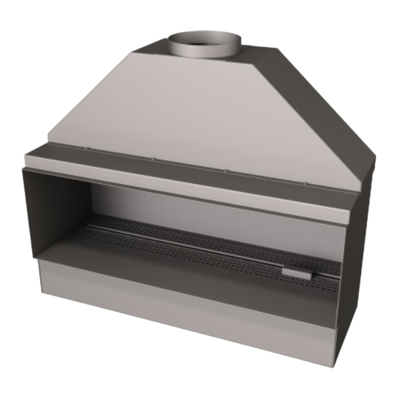
Page 8: Gas Burner Construction
Gas Burner Construction Use the image below to review the burner construction taking note of the positions of the main components and the required connections. The burner bar is pre-fitted to the enclosure. There is no reason why this should ever be removed. Before starting to install the appliance review the Data Plate fitted to the appliance for the gas type and pressure requirements of the appliance. -
Page 9: Remote Control System
Remote Control System Take some time to learn about the remote system fitted to this fire. The remote system features an RF (radio frequency) handset. The handset and the remote black box must be matched together to work correctly. Read the full section later in this manual to ensure you understand how the remote system works. -
Page 10: Installation Requirements
Installation Requirements This gas fire is intended for decorative purposes. The installation must be in accordance with National Regulations and must be carried out by a qualified Gas Safe Registered installer. Building work should only commence after a thorough survey of the intended location of the impending installation has been completed and it has been established that the unit can be installed and operated without risk to the owner or tenants of the property or their neighbours. - Page 11 Once installed all additional gas inlet holes in the enclosure must be sealed with metal tape to avoid flame reversal which will damage the remote. The enclosure and flue must be sealed in line with building regulations. It is important that the gas supply is disconnected before any old existing surround and hearth is removed.
-
Page 12: Building & Installation Work
BEFORE STARTING TO INSTALL CHECK: Gas Pipe Work: is it strong enough to supply this high power appliance? Did you check the flow rates as shown on page 4? Air Ventilation: First check if you are installing FR-850-V by checking the data plate within the fire. - Page 13 the excess brickwork to the required height, the base of the fire opening (which the Fire burner and enclosure will sit upon) has to be built. To create a seal around the appliance and allow correct operation of the flue, the original fire opening must be closed using bricks or blocks, infill the void around the enclosure using block work or rubble.
- Page 14 Above shows the minimum depth of the wall and the maximum lintel size when fitting the fire with the gather. Add 20mm to this for the front face of the finished wall (plaster board). The enclosure can be deeper however any voids should be filled otherwise there is a risk of “banging”...
- Page 15 Fireplace Clearance The fire must sit forward 20mm from the brickwork. This is for the plasterboard that will be added later to finish the installation and create a letterbox style. Position the enclosure in the opening so there is a minimum clearance of 10mm on each side and 10mm at the top.
- Page 16 With Gather The gather has a spigot to allow connection to a suitable flue liner. The diameter of the gather spigot depends on the model chosen – FR850-V (180mm) and FR850-NV (130mm) – See data plate. Page 16 of 54...
- Page 17 Once the fire is fixed in place the fire can be finished with plasterboard to create the final look required. The gas can now be connected and the fire commissioned. Page 17 of 54...
- Page 18 Connecting the Gas. Remove the vanity cover by taking out the screws as shown in the image. The gas line should now be connected to the 8mm inlet isolation valve with built in test point. Once connected perform a drop test to ensure no leaks in the pipe work up to the gas appliance.
- Page 19 Once the heat shield is removed the remote control is visible. Remove the shield from the remote box and switch on the power. Refit the remote heat shield. Refit the metal heat shield. Read the section on lighting the fire and how to operate the remote control - Read Page 40.
-
Page 20: Commissioning The Appliance
COMMISSIONING THE APPLIANCE WARNING: The burner inlet flow rates are factory set and cannot be changed. The aeration is fixed; do not change the burner aeration. This fire must not be operated without the heat shield in place over the remote system. Failure to do this will result in serious damage to the remote system which will not be covered by the warranty. - Page 21 IF THE TEST IS FAILED: If it is not possible to maintain the pressure • at the required level the problem may be caused by blockages in the pipework, incorrect pipe sizing or a faulty meter. If the problem is the meter then TRANSCO, BORD GAIS or the propane supplier must be called to adjust the governor.
- Page 22 FR850 – Log Layout - 14 Piece Log Set Fit logs numbered 4 & 3 Fit logs numbered 9 & 13 Add the Wool to the burner Add the Wool on top of cut out. Do not put wool near the pilot assembly.
- Page 23 Add logs numbered 14 & 17 Add logs numbered 5 & 8 Add logs numbered 15 & 11 Page 23 of 54...
- Page 24 Add logs numbered 16 & 6 Add logs numbered 10 & 12 Final layout Page 24 of 54...
- Page 25 FR850 – Pebble Layout – 20 Pebbles The fire is supplied with 20 pebbles of various colours. These are arranged with 9 Pebbles along the back, 11 pebbles along the front. The pebbles must not touch the burner and are positioned on the vanity cover. See images below. Add the Wool between the pebbles and along the burner bar.
-
Page 26: Final Safety Check List
Check the Flue System • Turn the appliance to the maximum setting. Leave the appliance for 10 minutes and then test that all the products of combustion are entering the flue by traversing the perimeter of the fireplace opening or canopy using a smoke generator e.g. - Page 27 Commissioning Checklist This product is guaranteed for 1 year from the date of delivery, as set out in the terms and conditions of sale. This guarantee will be invalid, to the extent permitted by law, if the above Commissioning Checklist is not fully completed by the installer. Installation Company…………………………………….………………………………………………..
-
Page 28: Fire Guards & Hearths
Warning: Fire Guards & Hearths This appliance is not fitted with an integral guard. In normal use consideration may be given to the use of a fireguard conforming to BS6539 or BS6778, so that the approach to the appliance is limited such that access to the flame is minimised It is recommended that a fireguard conforming to BS6539 or BS6778 is used for the protection of young children, the elderly and infirm. -
Page 29: Technical: Fault Diagnosis & Troubleshooting
Technical: Fault Diagnosis & Troubleshooting Every gas fire manufactured by Spirit Fires is tested at the factory and given a full 40 point performance check to ensure it operates correctly. It is highly unlikely that when installed in line with these instructions that it would not operate as designed. -
Page 30: Hand Set Error Codes
Faults – Hand Set Error Codes The handset will display an error code if a fault occurs. Refer to the separate sheet included with the manual for a full description of why the fire has failed. Typical Faults & Solutions Symptom Possible Cause and Solution Check spark lead is connected properly. -
Page 31: Spark Or Ignition Failure
Pilot Assembly / ODS There is a highly sensitive oxygen depletion sensor designed into the pilot light. If any part is damaged the entire unit must be replaced. Do not attempt to bend or alter the flame head, thermocouple or aeration hole. Use only genuine spare parts as similar looking parts from other appliances may well give different or inferior performance and could lead to a hazard. -
Page 32: Burner Flame
Burner Flame The flame on this type of appliance is normally directed towards the rear of the enclosure. This is normal due to the opening size and flue system. The flame will never stand “upright”. It is to be expected that over time the surface on the rear of the enclosure will tarnish. -
Page 33: Service And Aftercare Requirements
• That the owner has a copy of the installation and operation manual For Spare Parts please call 01325-327221 and ask for customer service. Spare parts are not returnable & Spirit Fires cannot accept responsibility for incorrect parts being ordered. When ordering replacement components or requesting technical assistance, you should at all times quote the following: •... -
Page 34: Servicing Instructions
Servicing Instructions The following servicing procedure should be carried out every 12 months and only by a registered Gas Safe Engineer. As foreign bodies, which can gather on the surface of the burner unit, it is inevitable that servicing can be a dusty operation therefore suitable precautions should be taken. -
Page 35: Spare Parts / Components List
• BURNER: Using a soft brush or vacuum cleaner, carefully remove any debris from the burner unit. • FINAL STEPS: Re-assemble the fire in the reverse order, and re- connect the gas supply and check for leaks. • Check the pilot assembly for a good strong flame. - Page 36 Page 36 of 54...
- Page 37 The Warranty is valid for 1 Year from date of delivery. To register the appliance complete the warranty card supplied and return to: Spirit Fires Limited. 4 Beaumont Square, Aycliffe Industrial Park, Newton Aycliffe, County Durham, DL5 6XN.
- Page 38 Contents Page 39 General Information Page 40 Start/Shutdown Instructions Page 49 Using the Manual Switch [if fitted] Page 50 Replacing the Batteries Page 51 Cleaning Instructions Page 52 Fire Guards and Hearths Page 53 Warranty Information Page 54 Contact Details Page 38 of 54...
-
Page 39: General Information
General Information A qualified GAS SAFE registered installer is required to fully install the appliance, failure to do this may render the appliance dangerous and will invalidate the warranty. This fire is intended for decorative purposes. Any purpose-provided ventilation should be checked regularly to ensure that it is free from obstruction. The fire should be serviced regularly by a qualified person. - Page 40 Lighting/Adjusting the Fire The appliance is supplied with an internal battery power supply and is operated via a handset. There are 3 x ‘AA’ batteries inside the appliance and 2 x AA batteries in the handset. Only use good quality alkaline batteries to ensure a long life from the handset and remote box.
-
Page 41: Operating Instruction
Mode – Time (12hour or 24 hr MAN (Manual), Zzz display) (Snooze), thermostat or timed Day of the week In Range of fire (missing if not in range or if Fire Control turned off) Gas fire burner status Room Temperature Battery condition –... - Page 42 Ensure the power isolator switch on the front corner of Fire Control Black Box within the Fire is in the on position (I). Note: The handset has a child safe function. To unlock the handset you must grasp the handset in the palm of your hand. The green unlock light will illuminate to show when the handset is unlocked and ready to accept commands.
- Page 43 Adjusting the Flame • Grasp the handset in the palm of the hand and sides to unlock the child safe mode. The green unlock light will illuminate. Keep the handset held to keep the control unlocked, to enable operation of the buttons. •...
- Page 44 Setting the Time Should you have to set the time or change the time you need to enter the SETUP menu. Hold the handset to unlock the keypad and keep held throughout the following steps, (if you release too soon the menu will exit and you will have to start again).
- Page 45 Setting the Hour Press and release the + or – button to change the hour to the correct hour and press set to store and to move to setting the minute. Repeat this for setting the minutes. Setting the temperature display to Celsius or Fahrenheit. Press and release the + or - button to toggle between C and F.
- Page 46 How to Find the Hand Set If you have misplaced the handset you can page it by pressing the + button only on the fire control for around 5 seconds. The handset will flash and make a noise to help you to locate it. Once you pick up the TESC it knows you hold it and so the sound stops.
- Page 47 Use these instructions to “Pair” the handset to the fire gas control inside the READ WARNING ABOVE BEFORE PROCEEDING. fire. Step 1 - Factory Reset of display handset This needs to be done first to enable the handset to be paired again. •...
- Page 48 N.B. If the display returns to the one shown above with the word “TESC” shown, then too much time has passed before pressing “SET” and so the handset has not paired yet. Simply repeat pairing again. N.B. Only ever press “+” and “-“ buttons together when pairing handsets. If done afterwards this will break the pairing made and a factory reset of the handset will need to be performed See Factory Reset of display handset later on in the instructions.
- Page 49 Thermostatic Mode The handset has within it a thermostat sensor and this can be set so the fire will heat the room to match the temperature set in the handset. Hold handset so that it unlocks then press and release the mode button several times as necessary until the display has a thermometer symbol flashing at the top of the display.
- Page 50 Replacing the Batteries Handset Batteries. To replace the handset batteries open the cover on the back of the handset. Remove the old batteries and using the diagram on the inside of the cover fit new high quality alkaline batteries. Main Appliance Batteries These are inside the gas fire body.
-
Page 51: Cleaning Instructions
Step 3: Remove the heat shield from the gas control. This is a special sleeve that is over the gas control. It must be replaced. Step 4: Remove the battery cover from the gas control. Remove the old batteries and using the diagram on the inside of the cover fit new high quality alkaline batteries. - Page 52 Removing the Burner Bar Deposits It is normal for the burner bar to show a reddish or white deposit. This is caused by bi-products of the gas being burnt and is unavoidable. This can be remedied by cleaning off the deposits with a using cloth then using a stove paint like Hotspot High Temperature Stove Paint which is sold in 100ml cans online for approx £7.
-
Page 53: Warranty Information
WARRANTY INFORMATION This appliance is supplied with a 12 month warranty from the date of delivery. The Warranty covers defective parts only and does not cover typical wear and tear that occurs with a gas fire appliance. This gas appliance carries full CE approval and has a long and reliable history. The fire is given over 40 function tests during the manufacturing process and is fully working before being shipped. - Page 54 ONLY USE GENUINE REPLACEMENT PARTS. Spirit Fires Ltd, 4 Beaumont Square Aycliffe Industrial Park, Newton Aycliffe County Durham, DL5 6XN T – 01325 327 221 F – 01325 327 292 www.spiritfires.co.uk sales@spiritfires.co.uk This revision is dated on the 14-10-2015. The information supplied in this manual is correct at the time of publication.
Need help?
Do you have a question about the FR850-NV and is the answer not in the manual?
Questions and answers