Table of Contents
Advertisement
Quick Links
Download this manual
See also:
User Manual
Advertisement
Table of Contents

Related Manuals for iCR iCR 3600


Summary of Contents for iCR iCR 3600
- Page 1 iCR3600 SERVICE MANUAL...
- Page 2 All other trademarks are the property of their respective owners, and are hereby acknowledged. Terms Any one of the following iCR products will be referred to as the “CR unit” throughout this document: iCR 1000 , iCR 1000 Dual...
-
Page 3: Contact Information
31a Ridlerstrasse, 80339 Munich, Germany Phone: +49.89.2555.757.150 Email: info@icrcompany.com Web: http://www.icrcompany.com iCR 3600 Information Please Enter the details of the iCR 3600 system here: Serial Number: Date Purchased: Interface Type: USB 2.0 c 2007-2009 ii of 61 Document # 3600-02A Rev C Confidential and Proprietary... -
Page 4: Safety Information
Laser Safety CAUTION This equipment employs a laser. Laser radiation may be present if the iCR 3600 is operated without the covers. Avoid the laser beam. Direct exposure to laser light must be avoided. - Page 5 The equipment must be serviced by properly trained technicians certified by iCRco, Inc. Do not connect the iCR 3600 with a damaged or sub-standard power cable. Do not use an extension cord with this device. The iCR 3600 should be properly grounded and power connections inspected to ensure safe operation.
- Page 6 Guidance and manufactures’ declaration – electromagnetic emissions The iCR 3600 is intended for use in the electromagnetic environment specified below. The customer or the user of the iCR 3600 should assure that it is used in such an environment. Emissions test Compliance Electromagnetic environment –...
- Page 7 ) for 0.5 ) for 0.5 hospital environment. If the user tions and cycle. cycle. of the iCR 3600 requires voltage continued operation during variations 40% U (60% 40% U (60% power mains interruptions, it is...
- Page 8 RF IEC to 80 MHz communications equipment 61000-4-6 should be used no closer to any 3 V/m 80 MHz 3 V/m part of the iCR 3600, including Radiated to 2.5 GHz cables, than the recommended RF IEC separation distance calculated 61000-4-3 from the equation applicable to the frequency of the transmitter.
-
Page 9: Icrco Warranty
To assess the electromagnetic environment due to fixed RF transmitters, an electromagnetic site survey should be considered. If the measured field strength in the location where the iCR 3600 is used exceeds the applicable RF compliance levels above, the iCR 3600 should be observed to verify normal operation. - Page 10 3600 – Service Manual defects in materials and workmanship under normal use for a period of one (1) year from the date of original shipment from iCRco. iCRco’s sole obligation under this warranty is limited to making reasonable efforts to ensure such conformity and to supply the consumer with a corrected version of the software as soon as it is practical after the consumer has notified iCRco of any non conformity.
- Page 11 3600 – Service Manual of the purchase documents, and sufficient information and authorization, including a liabil- ity release as to any loss of data (that should always be backed up), software or network injury, or downtime, allowing iCRco technicians remote access to the product. Product may not be returned to iCRco without first obtaining a Return Material Authorization (“RMA”)
-
Page 12: Revision History
3600 – Service Manual ARE LIMITED IN DURATION TO THE INITIAL WARRANTY PERIOD AND NO WAR- RANTIES, EXPRESS OR IMPLIED, WILL APPLY AFTER THIS PERIOD. ALL INFORMA- TION, SPECIFICATIONS, PRICES, AND SERVICES ARE SUBJECT TO CHANGE AT ANY TIME WITHOUT NOTICE. -
Page 13: Table Of Contents
Periodic Cleaning ........5.6.1 Cleaning the Outside of the iCR 3600 ....c 2007-2009... - Page 14 3600 – Service Manual 5.6.2 Cassette Cleaning ......6 Theory of Operation Product Overview .
- Page 15 3600 – Service Manual Removing Back Cover ....... Accessing the Scan Slot .......
-
Page 16: Introduction
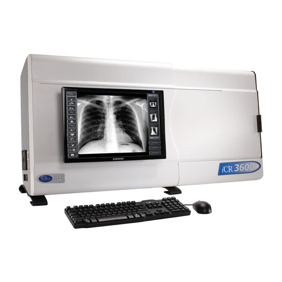
3600 – Service Manual 1. Introduction 1.1 Overview The CR unit is an ultra high resolution Computed Radiography device. It is designed to scan cassettes containing phosphor screens (CR plates) using patented technology. CR plates are transported past a scanning head without bending or using rollers. This flat scan path results in ultra high resolution images with high fidelity across the entire image. -
Page 17: Pre-Installation
95 F (10 to 35 C) operating, respectively. Installation of the iCR 3600 near high magnetic fields may cause the iCR 3600 to malfunction. The iCR 3600 should not be placed in a room with an MRI, CT, or any other equipment that produces high magnetic fields. -
Page 18: Power Switch Location
While the unit is scanning the yellow light will blink. 2.6 Physical Requirements The iCR 3600requires a stable operating environment. It is important the system is placed on a table, stand or wall mount that provides adequate support. 2.7 System Specifications... - Page 19 3600 – Service Manual Scan Rate Vibration/Acceleration Scan Rate 60 lines/second 3-4G Max (in shipping) Grey Scale Resolution Altitude 16 bits (65,535 shades of gray) Interface 0 to 9,500 ft. - operating USB 2.0 Weight Dimensions iCR 3600 10W x 22H x 44L inches...
-
Page 20: Hardware Installation
4. Store the box and any foam inserts somewhere safe & dry, so that if the iCR 3600 needs to be shipped again, there are packing materials available. -
Page 21: International Power Cable
– Service Manual 3.2.1 International Power Cable The iCR 3600utilizes an international IEC grade connector for the power cable. Systems are shipped with a standard NEMA 5-15 hospital grade cable. The cable needs to be changed depending on the male end, which varies from country to country. - Page 22 3600 – Service Manual Figure 3.2: 4. Carefully slide the computer into the computer mounting bracket (Figure 3.3). Note For easy access to the CD-ROM drive, make sure the drive opens towards the outside of the unit. Figure 3.3: 5.
-
Page 23: Wall Mounting Plates
3600 – Service Manual Figure 3.4: 3.5 Wall Mounting Plates Notice Wall mounting plates must be installed by a licensed contractor. c 2007-2009 8 of 61 Document # 3600-02A Rev C Confidential and Proprietary March 22, 2010 Property of iCRco, Inc. - Page 24 3600 – Service Manual 1. Attach the large wall mounting plate against wall at desired height. Allow the contractor to determine the proper screws to fasten the large wall mounting plate to the wall. 2. Attach the small wall mounting plate to the CR unit with three (3) 6-32 x ”...
-
Page 25: Software Installation
3600 – Service Manual 4. Software Installation 4.1 USB Driver Installation Installation of USB drivers are automatic with the installation of the iCRco software (i.e., QPC XSCAN32). 4.2 Installing QPC XSCAN32 QPC XSCAN32 software comes bundled with the CR unit. This software package will allow the user to interface with the CR unit. - Page 26 3600 – Service Manual 5. Make sure both QPC XSCAN32 Software and Software Key Driver boxes are checked, then click Next. 6. Select Scanning Station or Reading Station depend on the use, then click Next to con- tinue. 7. Select the appropriate modality, then click Next to continue.
- Page 27 3600 – Service Manual 9. The Destination Folder should be set to C: Xscan32 then click Next to continue. 10. The Program Folder name should be set to QPC XSCAN32, then click Next. 11. QPC XSCAN32 will begin to install. Be patient while XSCAN32 installs.
-
Page 28: System Operation
2. Make sure the power cord is properly installed in the UPS and the UPS is plugged into a standard wall outlet. 3. Make sure the USB 2.0 cord is properly installed in the iCR 3600 and computer. 4. Power on the computer. -
Page 29: Cassette Contamination
3600 – Service Manual 5.2.4 Cassette Contamination Should the situation arise where a cassette may come in contact with bodily fluids or other contaminated materials, place the cassette in a clean plastic bag before exposing the X-ray. This will ensure that the cassette stays clean and usable. -
Page 30: Acquiring An Image
3600 – Service Manual 4. Gently push the top of the cassette into place. 5. If loaded correctly, the user will see the white guide lines around the edge of the cassette. 6. Close the bay door. 5.4 Acquiring an Image WARNING This equipment employs a laser. - Page 31 6. Click on Scan to bring up the Quality Processing Center Scan dialog. (if it is a patient with no images the scan dialog will automatically appear). 7. The iCR Quality Processing Center dialog will appear. c 2007-2009 16 of 61 Document # 3600-02A Rev C Confidential and Proprietary...
- Page 32 3600 – Service Manual 8. Select the anatomy by mousing over the skeleton on the left hand side of the Quality Processing Center dialog. 9. Select the cassette size by clicking the correct button (i.e. 14x17 in, 10x12 in). This will start the scan.
- Page 33 3600 – Service Manual 13. Remove any collimation by using the Auto Crop(located in the main toolbar), Mask, or User Mask (located in the Image Processing dialog) functions. 14. Process using ICE or ICE2 (located in the Image Processing dialog).
- Page 34 3600 – Service Manual 17. Return to the Patient Information window. Select the patient(s) to send to a PACS or viewing station. If you wish to send more than one patient, hold the Ctrl key down and left mouse click to select multiple patients.
-
Page 35: Schedule Of Maintenance
5.6.1 Cleaning the Outside of the iCR 3600 Note It is important that the covers remain on the iCR 3600 at all times. The covers should only be removed for service by an iCRco authorized technician, then immediately replaced. CAUTION Do not clean the galvo mirror. Dust and fibers in the laser beam path may affect the radiographic image. - Page 36 3600 – Service Manual Cleaning the Outside of the Cassette 1. Moisten a clean, lint-free cloth with a mild soap or detergent using soft water. 2. Wipe down the cassette covers thoroughly. 3. Allow the cassette to air dry.
-
Page 37: Theory Of Operation
6. Theory of Operation 6.1 Product Overview The iCR 3600 is a desktop/wall mount/portable CR that scans one cassette at a time. It is designed to accomplish this in about one minute to enable high throughput for a high volume X-ray room. It can be mounted on the wall directly beside or behind an X-ray control panel. -
Page 38: System Configuration
6.2 System Configuration 6.2.1 Optical Beam Path The iCR 3600 contains a 664 nm 80 mW laser, laser power supply, Lens optic and two mirrors, a scanning galvanometer, and a light collection system. The round laser spot is focused through a collimation lens to produce a round output beam. -
Page 39: Pmt Board
3600 – Service Manual 6.2.5 PMT Board The photomultiplier tube amplifies the photons from the CR plate and converts them into electrical signals. 6.2.6 Power Distribution Board WARNING Do not handle supply when unit is on. Do not disconnect cables when unit is powered up. -
Page 40: Pmt Amplifier
3600 – Service Manual 6.2.11 PMT Amplifier The amplifier is the interface between the PMT receiving the stimulated light from the collection chamber. The amplifier serves as a current to voltage converter and a log amplifier. c 2007-2009 25 of 61 Document # 3600-02A Rev C Confidential and Proprietary... -
Page 41: Diagnostics
1. Make sure the iCR 3600 is powered by at least a 1300VA (780W) UPS (uninteruptable power supply). 2. Make sure that the iCR 3600 is connected to the acquisition computer using a USB 2.0 cable (USB 1.0 or 1.1 cabling is not sufficient). -
Page 42: Using The Focus Tool For Hardware Diagnostics
The Focus tool is an efficient test that can provide the Service Engineer with valuable feed back regarding the functionality of the iCR 3600’s hardware. There are a series of questions following the work instructions that are designed to help include/eliminate potential failures in the iCR 3600’s subsystems. - Page 43 2,500, you may need to re-adjust the zero point of the scanner. 7. Open the dust cover of the iCR 3600, the Data line should rise and lower slightly according to the position of the bay door. If the room is illuminated by high frequency fluorescent lights, the line may become sinusoidal (Wavy) and move away from the...
-
Page 44: Image Symptoms
3600 – Service Manual If the focus tool does not come up, what questions can we ask? 1. Is there power to the unit (Green Power light on and steady?, Orange scan light off, or on and blinking?) 2. Does the unit move before an error condition is seen? If so, motor is working and carriage is functioning. -
Page 45: Dust Lines
3600 – Service Manual 7.3.2 Dust Lines Symptom: Light, blurred lines across the long axis of the cassette. Cause: Dust or lint on the mirrors. Solution: To clean the mirrors, please see Section 8.11 for instructions. 7.3.3 Horizontal Lines in Image Symptom: Horizontal lines in Images. -
Page 46: Banding Top/Bottom 17" Length
3600 – Service Manual Solution: 1. Ensure that there is no blockage in the cassette scan path. 2. If there is no blockage of the scan path, the user may need to reposition the Caterpillar Brush. Please see Section 8.13 for instructions. If the Caterpillar Brush is worn out, please contact Technical Support to obtain a replacement brush. -
Page 47: Up-Side Down Cassette
3600 – Service Manual 7.3.5 Up-side Down Cassette Symptom: Honeycomb/hexagonal pattern throughout the image. Cause: Exposing a cassette up-side down. Solution: First ensure that the cassette is erased, then re-expose the cassette with the carbon-fiber side facing up, then re-scan. -
Page 48: Eraser Offset
3600 – Service Manual Solution: To alleviate grid lines/ moir´ e effect, first ensure that the grid being used is 178 LPI. If the grid in use is 178 LPI, then rotate the cassette 90 under the grid. 7.3.7 Eraser Offset Symptom: A gap of white space between the edge of the image and the physical edge of the cassette after scanning. -
Page 49: Image Jitter
3600 – Service Manual 7.3.8 Image Jitter Symptom: Jittery image. Cause: Inconsistency in the CR unit’s galvanometer. Solution: Image jitter issues are not serviceable in the field. Please contact Technical Support for assistance with image jitter. 7.3.9 Over Exposure Symptom: Lines in images / images look more “translucent”–... -
Page 50: Random Imaging Shifting
3600 – Service Manual Solution: Make an exposure using your current exposure settings. Scan and evaluate the image. Then, reduce the exposure parameters, expose another plate, then scan and evaluate the image. Compare the results of both exposures, then adjust the “standard” exposure accordingly. -
Page 51: No Motor Movement
3600 – Service Manual 4. Make sure the CR unit is recognized in the Windows Device Manager. Additionally, make sure the device drivers are properly installed. To do this: (a) Go to Start Control Panel System Hardware Device Manager (b) In the Device Manager, make sure there are no unrecognized USB devices. -
Page 52: Clicking Noise Returning To Home
3600 – Service Manual 7.4.3 Clicking Noise Returning to Home Symptom: Clicking noise heard from CR unit when returning to the home position. Cause: At the end of the scan: Eraser offset. At home position: Fuses / sensor. Solution: At the end of the scan: Change eraser offset. -
Page 53: Cassette Stuck In Cr Unit
3600 – Service Manual Solution: A broken catch is not serviceable in the field. Please contact Technical Support for more information. 7.4.7 Cassette Stuck in CR unit Symptom: Cassette stuck in CR unit. Cause: Misloaded cassette / pressure from Caterpillar Brush. -
Page 54: Failure Analysis
3600 – Service Manual as USB 1.0. In some instances, unplugging and replugging the USB cable can correct this. 2. After clicking on the scan button, listen for the motor and see if the CR slide moves at all. If it does not move at all, then the motor controller board may be at fault. - Page 55 3600 – Service Manual Motor movement and magnet/reed switch are most likely functional as RETURN TO HOME followed by START SCAN commands operate without apparent error. These commands are executed prior to expecting laser triggers. Setup: 1. Power off the CR unit.
- Page 56 3600 – Service Manual 2. If the galvo mirror is not oscillating, STOP! Possible failures: Bad PMT board or cabling Bad Galvo/Controller or cabling Bad Quad Power Supply or cabling If a fix has not been accomplished by this point, the machine should be returned to the factory for repair.
-
Page 57: Service & Maintenance Procedures
3600 – Service Manual 8. Service & Maintenance Procedures 8.1 Removing Front Cover 1. Make sure the CR unit is powered off. Remove the power cord from the unit. 2. Orient the CR unit on its back. 3. Remove four (4) 10-32 x ”... -
Page 58: Removing
3600 – Service Manual removing it from the door. 8.2 Removing Back Cover 1. Make sure the CR unit is powered off. Remove the power cord from the unit. 2. Remove nine (9) 6-32 x ” flathead undercut screws from the back cover. - Page 59 3600 – Service Manual 4. Remove four (4) 6-32 x ” flathead screws from the front cover. 5. Slide the top cover back, then lift the cover off. 6. Slide the door to the open position. 7. There is a plastic release latch on the underside of the door. Squeeze the latch towards the feet of the unit to release the door from the door slide, then slide the rail back, removing it from the door.
- Page 60 3600 – Service Manual 8. Remove two (2) 6-32 x ” & two (2) 6-32 x 1” truss head from the brush bar cover. 9. The scan slot is located under the brush bar cover. c 2007-2009 45 of 61 Document # 3600-02A Rev C Confidential and Proprietary...
-
Page 61: Replacing The Pmt Board
3600 – Service Manual 8.4 Replacing the PMT Board 1. Make sure the CR unit is powered off. Remove the power cord from the unit. 2. Remove nine (9) 6-32 x ” flathead undercut screws from the back cover. - Page 62 3600 – Service Manual 5. Remove the USB, phone jack and four (4) power connectors from the PMT board. 6. Remove six (6) 4-40 x ” screws from the PMT board. 7. Ease the PMT board from the PMT Tube contacts.
-
Page 63: Removing The Optical/Electrical Module From The Case
3600 – Service Manual 8.5 Removing the Optical/Electrical Module from the Case 1. Make sure the CR unit is powered off. Remove the power cord from the unit. 2. Remove nine (9) 6-32 x ” flathead undercut screws from the back cover. - Page 64 3600 – Service Manual 8. Slide the door to the open position. 9. There is a plastic release latch on the underside of the door. Squeeze the latch towards the feet of the unit to release the door from the door slide, then slide the rail back, removing it from the door.
-
Page 65: Replacing The Motor Controller Board
3600 – Service Manual 11. Add masking tape over the Scan Slot to minimize dust entry into the system. 12. Remove eight (8) 10-32 x ”screws from the chasis. 13. With two (2) or more people, lift the module out of the outer shell. - Page 66 3600 – Service Manual 2. Using a small flathead screw driver, unscrew the wires from the Motor Controller board. 3. Remove the phone cord from the Motor Controller board. 4. Using a pair of needle nose pliers, pinch each of the four (4) fasteners, freeing the Motor Controller board.
-
Page 67: Replacing The Main Power Supply
3600 – Service Manual 5. Remove the Motor Controller board from the CR unit. 6. Replace the Motor Controller board, then reassemble the CR unit in the reverse order from taking it apart. 8.7 Replacing the Main Power Supply 1. - Page 68 3600 – Service Manual 3. Unscrew four (4) 6-32 x ” screws from the Main Power Supply. 4. Remove the Main Power Supply from the CR unit. 5. Replace the Main Power Supply, then reassemble the CR unit in the reverse order from taking it apart.
-
Page 69: Replacing The Galvo Controller Board
3600 – Service Manual 8.8 Replacing the Galvo Controller Board 1. Remove the module from the case, as covered in Section 8.5 on page 48. 2. Remove the connectors from the board. 3. Remove two (2) Allen bolts and nuts. -
Page 70: Cleaning The Fan Filter
3600 – Service Manual 3. Remove four (4) 6-32 x ” screws, washer, and lock washer from the Power Distribu- tion board. 4. Remove the Power Distribution board from the CR unit. 5. Replace the Power Distribution board, then reassemble the CR unit in the reverse order from taking it apart. -
Page 71: Cleaning The Mirrors
3600 – Service Manual 3. To clean the filter, wash throughly in warm water, then air dry the filter over night. 8.11 Cleaning the Mirrors 1. Make sure the CR unit is powered off. Remove the power cord from the unit. -
Page 72: Checking The Fuses
3600 – Service Manual 5. Apply the glass cleaner on the soft, lint-free tissue. Do not put cleaner directly on the mirrors. Clean the mirrors in a circular motion and do not apply much force. Use a flashlight to make sure that there are no dust particles or smearing residue on mirrors. -
Page 73: Power Distribution Board Fuses
3600 – Service Manual 4. The fuses are located on the back of the fuse housing. 5. The fuses are 3A/250V. 8.12.2 Power Distribution Board Fuses 1. Make sure the CR unit is powered off. Remove the power cord from the unit. -
Page 74: Changing The Brushes
3600 – Service Manual 8.13 Changing the Brushes 1. Make sure the CR unit is powered off. Remove the power cord from the unit. 2. Remove the front cover, as covered in Section 8.1. 3. Remove two (2) 6-32 x ”... -
Page 75: Brush Bar Brushes
3600 – Service Manual 1. To remove the Caterpillar Brush, ensure that there are no brush clips holding it down. 2. If there are brush clips, remove the four (4) 4-40 x ” or ” (depending on the CR model) panhead screws from the light bar. - Page 76 3600 – Service Manual 1. To remove the Brush Bar Brushes, remove six (6) 6-32 x ” flathead undercut screws from the Brush Bar. 2. Slide the old brush out of its holder. 3. Trim any stray brush hairs from the new brush using a razor blade.
Need help?
Do you have a question about the iCR 3600 and is the answer not in the manual?
Questions and answers