Table of Contents
Advertisement
Advertisement
Table of Contents

Related Manuals for IFM Electronic TN2511


Summary of Contents for IFM Electronic TN2511
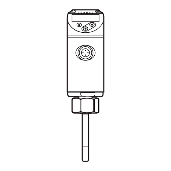
- Page 1 Operating instructions Electronic temperature sensor TN2511...
-
Page 2: Table Of Contents
Contents 1 Safety instructions �����������������������������������������������������������������������������������������������3 2 Functions and features ����������������������������������������������������������������������������������������3 3 Function ���������������������������������������������������������������������������������������������������������������3 3�1 Switching function ������������������������������������������������������������������������������������������4 3�2 Analogue function ������������������������������������������������������������������������������������������5 3�2�1 Current output ���������������������������������������������������������������������������������������5 3�2�2 Voltage output ���������������������������������������������������������������������������������������6 3�3 Display colour change �����������������������������������������������������������������������������������7 3�3�1 Parameter r1ou, G1ou ��������������������������������������������������������������������������7 3�3�2 Parameter r-cF, G-cF ����������������������������������������������������������������������������8 3�4 IO-Link �����������������������������������������������������������������������������������������������������������8 3�4�1 General information ������������������������������������������������������������������������������8 3�4�2 Device-specific information �������������������������������������������������������������������8... -
Page 3: Safety Instructions
9�2 Error indications / self-diagnostics ���������������������������������������������������������������18 10 Technical data ��������������������������������������������������������������������������������������������������18 11 Factory setting �������������������������������������������������������������������������������������������������19 1 Safety instructions • Please read this document prior to set-up of the unit� Ensure that the product is suitable for your application without any restrictions� •... -
Page 4: 3�1 Switching Function
3.1 Switching function OUT1 changes its switching status if it is above or below the set switching limits� Hysteresis or window function can be selected� Hysteresis function Window function T = Temperature T = Temperature SP1 = set point FH1 = upper limit value rP1 = reset point FL1 = lower limit value HY = hysteresis... -
Page 5: 3�2 Analogue Function
3.2 Analogue function • The unit converts the measured signal into a temperature-proportional ana- logue signal� Depending on the parameter setting the output signal is at: 4���20 mA [ou2] = I 20���4 mA [ou2] = I 0���10 V [ou2] = U 10���0 V [ou2] = U •... -
Page 6: 3�2�2 Voltage Output
In case of internal fault, the output signal behaves according to the parameter set in [FOU2]: [FOU2] = On [FOU2] = OFF [ou2] = I 21 mA 3�5 mA [ou2] = I 3�5 mA 21 mA 3.2.2 Voltage output Maximum measuring range at [ou2] = U Measuring range scaled at [ou2] = U U [V] U [V]... -
Page 7: 3�3 Display Colour Change
3.3 Display colour change The colour of the characters in the display can be set via the parameter [colr]� With the parameters rED (red) and GrEn (green), the display is permanently set to one colour� Via further parameters, the colour of the characters changes according to the measured value: OUT1 OUT1 and OUT2... -
Page 8: 3�3�2 Parameter R-Cf, G
3.3.2 Parameter r-cF, G-cF Colour change if the measured value is within definable limits� 3.4 IO-Link 3.4.1 General information This unit has an IO-Link communication interface which requires an IO-Link-capa- ble module (IO-Link master) for operation� The IO-Link interface enables direct access to the process and diagnostic data and provides the possibility to set the parameters of the unit during operation�... - Page 9 Mounting dimensions with Mounting dimensions with Mounting dimensions with M12 adapter G¼ adapter G½ adapter Before installing and removing the unit: Ensure that no medium can leak at the process connection� ► Grease the threads of the process connection (1), adapter (2) and nut (3)� The sensor tip (A) must not be in contact with grease�...
-
Page 10: Electrical Connection
5 Electrical connection The unit must be connected by a qualified electrician� The national and international regulations for the installation of electrical equipment must be adhered to� Voltage supply to EN 50178, SELV, PELV� ► Disconnect power� ► Connect the unit as follows: BK: black BN: brown OUT2... -
Page 11: Operating And Display Elements
6 Operating and display elements 1, 2, 3: Indicator LEDs • LED 1 = switching status OUT1 (lights if output 1 is switched) • LED 2 = temperature in the indicated unit of measurement • LED 3 = no function 4: Alphanumeric display, 4 digits •... -
Page 12: Menu
7 Menu 7.1 Process value display (RUN) and menu structure - - - - °C °F Hno Hnc Fno Fnc Ineg U Uneg 0,0...50 s 0,0...50 s FOU1 OFF On ASP2 FOU2 OFF On AEP2 °C °F PnP nPn 0,0 °C 0,0 °C -10...10 °C GrEn r1ou G1ou... -
Page 13: 7�2 Explanation Of The Menu
7.2 Explanation of the menu Set point (upper limit value) with hysteresis function Reset point (lower limit value) with hysteresis function Set point (upper limit value) with window function Set point (lower limit value) with window function ASP2 Analogue start point AEP2 Analogue end point Extended functions�... -
Page 14: Parameter Setting
coLr Colour configuration of the display: = Process value always red� GrEn = Process value always green� r1ou = Process value red in case of switched output OUT1� G1ou = Process value green in case of switched output OUT1� r-cF = Display red if measured value between limit values cFL���cFH, irrespective of the output function�... -
Page 15: 8�1 Parameter Setting In General
8.1 Parameter setting in general 1� Change from the RUN mode to the main menu [●] 2� Select the requested parameter [▲] or [▼] 3� Change to the setting mode [●] 4� Modification of the parameter value [▲] or [▼] > 1 s 5�... -
Page 16: 8�1�3 Locking / Unlocking
8.1.3 Locking / Unlocking The unit can be locked electronically to prevent unintentional settings� On delivery: not locked� Locking ► Make sure that the unit is in the normal operating mode� ► Press [▲] and [▼] simultaneously for 10 s until [Loc] is displayed. During operation: [Loc] is briefly displayed if you try to change parameter values�... -
Page 17: 8�1�7 Read The Min/Max Values
8.1.7 Read the min/max values ► Select [Hi] or [Lo] and read the value� [Hi] [Lo] [Hi] = max� value, [Lo] = min� value� Delete memory: ► Select [Hi�T] or [Lo�T]� ► Briefly press [●]. ► Keep [▲] or [▼] pressed. >... - Page 18 9.2 Error indications / self-diagnostics Diplay Warning message [SC1] Excessive current at OUT1� LED1 for OUT1 flashing� [OL] Detection zone exceeded� [UL] Below the detection zone� [C�Loc] Setting pushbuttons locked, parameter change rejected� Active IO-Link communication� [S�Loc] Setting pushbuttons locked, parameter change rejected� Unlock using parameter setting software�...
- Page 19 11 Factory setting Factory setting User setting 60 °C 50 °C ASP2 -40 °C AEP2 150 °C FOU1 FOU2 °C coLr Further information at www�ifm�com...
Need help?
Do you have a question about the TN2511 and is the answer not in the manual?
Questions and answers