Table of Contents
Advertisement
Quick Links
Advertisement
Table of Contents

Subscribe to Our Youtube Channel
Related Manuals for APart-Audio MA246


Summary of Contents for APart-Audio MA246
- Page 1 MANUAL MA246/R/MR INFO@APART-AUDIO.COM...
-
Page 2: Main Features
All other zones will hear the paging message: the MA246 will disconnect these zones from the internal amp and will send the paging signal to the ex- ternal amp. The external amp will feed the signal to the selected zones via the MA246. When paging is finished, the zones will automatically be switched back to the internal amp. -
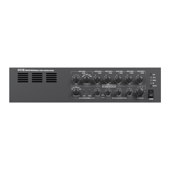
Page 3: Front Panel
24. Power switch : switch mains power on and off. This switch turns off the amplifier when connected to the mains AC supply. Please note that this switch does not switch the amp off when operating from a 24 VDC emergency power supply. INFO@APART-AUDIO.COM... - Page 4 A maximum of 180 watts speaker load is allowed per zone, with a total maximum of 240 watts for all zones when using the internal MA246 power amplifier only. Do not overload the amplifier. If the amplifier is overloaded, it will result in overheating the amplifier. Check your total speaker load with an impedance or wattmeter before operating the amplifier.
-
Page 5: Rear Panel
VR13. The jumper and level adjustment are located inside the unit on the rear PCB. In order to reach them you will need to open the unit. For authorized persons only. INFO@APART-AUDIO.COM... - Page 6 8. Emergency input level : this is the only level control on the emergency input. The emergency signal bypasses all possible level controls in the MA246 unit. 9. Chime level: turn this knob to activate the two tone chime. The chime is activated by the priority switches from mic/line 1 –...
- Page 7 5 and 6, these are the 70 volts zones by default. When powered by the internal MA246 amp, the load on the internal amplifier is only half of the power compared to the power in 100 volt. When you switch these zones to the external paging amp, these silent zones will become 100 volt zones, meaning that the external amp will see double the power compared to the internal amplifier.
-
Page 8: Microphone Connections
Alternatively, you can connect the unbalanced signal ground to the – connector and the ‘hot’ wire to the + connector. By leaving the ground connection unused, you can avoid a lot of ground loop problems (such as hum, excessive noise…) Unbalanced MIC/LINE signal connection WWW.APART-AUDIO.COM... -
Page 9: Priority Levels
(see priority level table). Connect red wire to +, white wire to -, shield+yellow wire to GND, black wire to PG1, blue wire to PG2. You can preset the paging groups 1 and 2 using the dipswitches at the rear of the MA246. The paging group settings are equal for mic 2 to 4. MICPAT-6 connection MICPAT-6 must be connected to the PAGING INPUT 1 : connect the RJ45 plug to the selective paging station RJ45 connector. - Page 10 What about external volume controls ? If you use additional external volume controls, such as our E-VOL series, be sure to connect the 24 volt priority output from the MA246 to the volume control’s 24 V priority input. This will bypass the external volume controls, allowing paging messages to be heard at full power.
- Page 11 From the factory, there is no wire bridge as shown in the picture. That’s because we want to encourage you to use the MA246 as a switching centre in high quality BGM and paging systems where all zones are individually pageable without interrupting the BGM in the non paged zones.
- Page 12 WWW.APART-AUDIO.COM...
- Page 13 Difference in MA246R front panel controls: Music selector 3 and 15 have 3 aux source inputs + internal tuner (MA246 has 4 aux source inputs). On the left side of the front panel you will find a digital tuner. Operation of the tuner will be explained later.
- Page 14 MA246MR Music selector 3 and 15 have 2 aux source inputs + internal tuner and CD/MP3 section (MA246 has 4 aux source inputs). On the left side of the front panel you will find a digital tuner and the CD/MP3 player. Operation of the tuner and CD/MP3 player will be explained later.
-
Page 15: Tuner Operation
FM steps are 100 kHz by default, press the +5 button to step up 50 kHz in the FM band. Note: after powering on the MA246R/MA246MR main unit, the tuner is automatically powered on. INFO@APART-AUDIO.COM... - Page 16 If you enter program mode, PROGRAM is displayed in the display, the numeric characters show folder number, track number and program step number. Enter program mode, select a folder and track and press shuffle to enter the selected folder/track. The last last characters show the program WWW.APART-AUDIO.COM...
- Page 17 Note: the CD player will play normal audio CD’s and CDR’s containing PCM audio files or wav files, MP3’s or WMA files. The USB and CARD reader will only read MP3’s or WMA files. ID3 tag and folder names are not displayed. For maximum compatibility, avoid media containing other than the supported file types. INFO@APART-AUDIO.COM...
-
Page 18: Technical Specifications
Technical Specifications SPECS MA246 ‐ MA246R ‐ MA246MR GENERAL SPECS !utput power ra+ng RMS 240 wa4 Frequency response 100 volt out 40 ‐ 25 kHz +1/‐3dB Total harmonic distor+on <0,3% @ ‐6dB, 1kHz Frequency response line output zone 1 20 ‐ 30 kHz +1/‐3dB Bass tone control zone 2‐6 +8/‐ 8dB @ 100Hz Treble tone control zone 2‐6 +8/‐8dB @ 10kHz Tone control mic/line 1‐4 from 100Hz/+3dB, 10kHz/‐6dB to 100Hz/‐9dB, 10kHz/+4dB S/N ra+o (20Hz‐20kHz) amplifier in: >95dB line in: >80dB mic in: >65dB Indicator leds zone paging : 6 x yellow led muted by priority : 1 x red led Limiter ac+vity : 1 x red led Signal 100% : 1 x yellow led Signal ‐25dB : 1 x green led Power on : 1 x green led Protec+on ac+ve : 1 x red (also lights up during power on) Zone controls Individual volume and source selec+on for zone 1 line output 5 x 100 volt volume controls for zone 2‐6 Source controls Music selector zone 2‐6 Music selector zone 1 music level control zone 2‐6 mic/line 2‐4 volume control all zones Master level control zone 2‐6 ... - Page 19 Under no circumstance, APart-Audio or one of its service centres can be held responsible for the loss of data caused by a repair or exchange operation.
-
Page 20: Safety Instructions
• Do not drive the inputs with a signal level higher than that required to drive equipment to full output. • Do not run the output of any amplifier back into another input. •In case of mal-function this device should be serviced by qualified service personnel only. MA246 is developed by Audioprof nv Lanteernhofstraat 90...
Need help?
Do you have a question about the MA246 and is the answer not in the manual?
Questions and answers