Cognex DataMan 100 Quick Reference Manual
Id readers
Hide thumbs
Also See for DataMan 100:
- Quick reference manual (18 pages) ,
- Removal instructions (2 pages) ,
- Quick reference (16 pages)
Table of Contents
Advertisement
Advertisement
Table of Contents

Related Manuals for Cognex DataMan 100


Summary of Contents for Cognex DataMan 100
- Page 1 COGNEX ® DataMan ® Quick Reference Guide...
-
Page 2: Getting Started
Connect your DataMan Basic I/O Module • Wiring the Expansion I/O Module Using your DataMan Page 22 DataMan 100 Trigger types • Trigger Modes • Training • Training Feedback DataMan 100 Specifications • DataMan 100 Cable Pinout Reference Information • Digital Input Wiring Diagrams • Digital Output Wiring Page 27 Diagrams •... - Page 3 (DM100-PIVOTM-00) (DM100-DMPL-000) *Note: USB/RS-232 extension connection is possible with the following limitations: 1. The USB connection is shorter than 5m. 2. Serial connection is shorter than 15m. 4 DataMan 100 Quick Reference Guide DataMan 100 Quick Reference Guide 5...
-
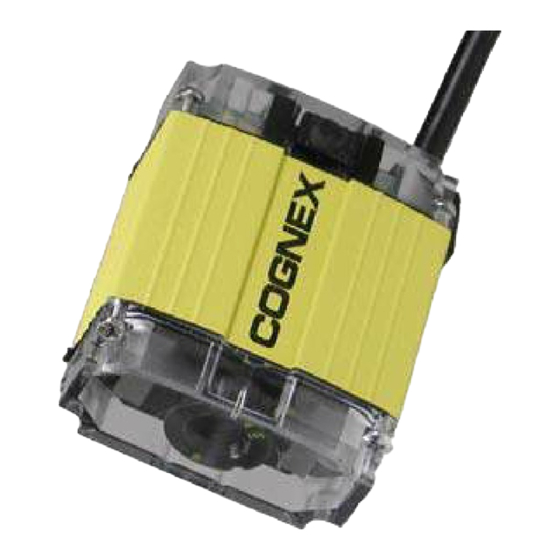
Page 4: Product Overview
Status LED • Red: no read • Green: read Pushbutton Use a DataMan 100 Ground Isolator to prevent mounting your DataMan 100 to conductive material that can provide an electrical path to ground, which 19.5 • Push to read may cause data loss or unreliable operation. -
Page 5: Troubleshooting
• Scan the correct connection code on page 15 or 17. 5. Click Refresh to update the list of connected devices. • If you are using your PC’s USB to power the DataMan 100, make sure that your PC’s USB port can supply enough power (2.5W peak). Connect 6. -
Page 6: Setting The Focus Position
This chart shows the horizontal field of view for the shown. Maximum torque The size of the holes in DataMan 100 and DataMan 100-LA at a range of working for the cover screws is 9 the standard lens cover distances. -
Page 7: Reading Distances
10 mil positions (40mm, 65mm, and 105mm). The working distances for both the standard DataMan 12 mil 100 and the DataMan 100- LA (large-aperture) are shown. 12 DataMan 100 Quick Reference Guide DataMan 100 Quick Reference Guide 13... -
Page 8: Usb Connections
USB Connections When connected to a PC over USB, the DataMan 100 appears as either a COM port or as a standard USB keyboard. You control the connection type by scan- ning the appropriate connection code. Make the connection by... - Page 9 RS-232 Connections You can connect the DataMan 100 to a PC or other device over a standard RS-232 serial connection. NOTE: You must supply external power to use this Scan the connection code connection type. NOTE: Serial connections from Make the connection by...
-
Page 10: Output Wiring Example
Trigger Input: Opto-isolated, polarity-independent, current source – or sink. Input 0 is dedicated trigger line. RS-232 and USB: If USB connection is detected, USB communications is automatically selected; otherwise RS-232 connection is used. 18 DataMan 100 Quick Reference Guide DataMan 100 Quick Reference Guide 19... -
Page 11: Input Wiring Example
Power: 24 VDC + 10%, 4.2W peak. TRIGGER − TRIGGER + Trigger Input: Opto-isolated, polarity-independent, current source INPUT 7 or sink. Directly wired to DataMan 100 input line 0. INPUT 6 INPUT 5 INPUT 4 COMM OK Outputs: Six extended output lines configurable using the DataMan... -
Page 12: Trigger Modes
Setup tool. until multiple images containing as many codes as specified in multicode mode are located, or until the trigger is released. 22 DataMan 100 Quick Reference Guide DataMan 100 Quick Reference Guide 23... -
Page 13: Training Feedback
Optimize Lighting exposure time: button to optimize lighting. • One: > 0.4 msec • Two: < 0.4 msec • Three: <= 0.2 msec 24 DataMan 100 Quick Reference Guide DataMan 100 Quick Reference Guide 25... - Page 14 LPS or NEC class 2 power supply • DataMan 100 and Ex- 24 VDC ± 10% tended I/O Module 4.2 W maximum LPS or NEC class 2 power supply 26 DataMan 100 Quick Reference Guide DataMan 100 Quick Reference Guide 27...
- Page 15 Green connector, not I/O Device (TTL) DM100 (load) module. In 0 Yellow Reserved 3 KΩ Yellow/Black Reserved Note: Colors are of individual wires within I/O cable. 28 DataMan 100 Quick Reference Guide DataMan 100 Quick Reference Guide 29...
-
Page 16: Digital Output Wiring Diagrams
DM100 (sinking) Out 0/1 Device DM100 10 Ω In 0 – 3 KΩ 470 Ω @ 5V Pull-up resistor required (R1): 2.2 KΩ @ 12V 4.7 KΩ @ 24V 30 DataMan 100 Quick Reference Guide DataMan 100 Quick Reference Guide 31... -
Page 17: Multi-Port Connections
Multi-Port Connections Digital Output Wiring Diagrams (Continued) You can connect multiple DataMan 100 readers to a single PC (or other device equipped with a serial port) using a multi-port connection. Sinking Outputs, Sinking Inputs A multi-port connection creates a daisy-chain of readers. Each reader... - Page 18 Configure for Multi-Port Operation and Rx Data pins on adjacent connectors must be connected to provide the You must connect the Setup tool to each DataMan 100 in turn using a USB multi-port connection. connection and set the DataMan for multi-port operation. To configure...
-
Page 19: Multi-Port Usage Notes
COGN EX COGN EX • There is no fixed limit to the number of DataMan 100 readers that you can connect to a single PC. Each reader introduces a delay of about 100 msec when it retransmits received serial data. If you have 5 readers, this means that there will be a 400 msec delay between the time the first reader in the chain transmits data and the PC receives it. -
Page 20: Warnings And Notices
5 / 6 1 Stop, Even Value Code , 1 Stop, None 38,400 Baud 8-1-even 1 Stop, Odd , 1 Stop, None 5 / 6 57,600 Baud 8-1-odd 38 DataMan 100 Quick Reference Guide DataMan 100 Quick Reference Guide 39... -
Page 21: Compliance Statements
Compliance Statements with the instructions, may cause harmful interfer- The DataMan 100 series meets or exceeds the re- Cognex Corporation shall not be liable for use of our ence to radio communications. Operation of this quirements of all applicable standards organizations product with equipment (i.e., power supplies, personal... - Page 22 Reset Scanner to Factory Defaults Copyright © 2015 Cognex Corporation All Rights Reserved. This document may not be copied in whole or in part, nor transferred to any other media or language, without the written permission of Cognex Corporation. The hardware and portions of the software described in this document may be covered by one or more of the U.S.
Need help?
Do you have a question about the DataMan 100 and is the answer not in the manual?
Questions and answers