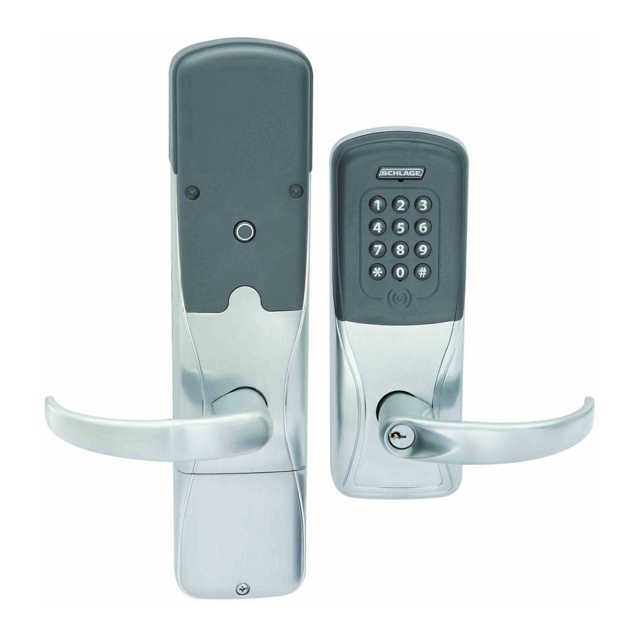
Schlage AD-400 User Manual
Hide thumbs
Also See for AD-400:
- Quick manual (42 pages) ,
- Instruction manual (16 pages) ,
- User manual (16 pages)
Table of Contents
Advertisement
Advertisement
Table of Contents

Summary of Contents for Schlage AD-400
- Page 1 *P516-127* P516-127 AD-400 AD-401 Networked wireless lock user guide Instructions for adaptable series networked wireless locks Para el idioma español, navegue hacia www.allegion.com/us Pour la portion française, veuillez consulter le site www.allegion.com/us...
-
Page 2: Table Of Contents
UL Listed product, in accordance with the requirements of the Standards UL294 and ULCS319. This product has been evaluated for ULC-S319 Class I. 2 • Schlage • AD-400 user guide... -
Page 3: Overview
Overview The Schlage AD-400 is an open architecture Wireless Access Point Module (WAPM) designed to interface with third-party panels through a PIM400. The Schlage AD-401 is a FIPS-201-1 certified Wireless Access Point Module (WAPM). • The AD-400/AD-401 communicates with the PIM400 via RF (radio frequency). -
Page 4: Getting Started
When in a low battery condition the lock may operate but not have sufficient power to communicate with the SUS. When intitiating SUS communication, the Schlage button will light solid red for one second to indicate power is not sufficient. If this should occur, change the batteries immediately. See Batteries on page 12. -
Page 5: Optional Inside Push Button (Ipb)
The IPB may be used to communicate a lock/ unlock request or be completely ignored by the network software. • AD-400 IPB activity will only be reported to control systems connected to a PIM400-485 with a RS-485 connection. •... -
Page 6: Construction Access Mode
In the factory default state, locks with keypads have a default PIN of 13579 and “#”, which can be used for installation, testing and construction access. To test, enter default PIN. The Schlage button will blink and the lock will unlock. -
Page 7: Locks With Card Readers - Add Construction Access Mode User Credentials
Reset the lock to factory settings. See Reset to factory default settings on page 10 for more information. When construction mode is cancelled, the master construction credential and all other credentials added using the master construction credential will no longer function. 7 • Schlage • AD-400 user guide... -
Page 8: Link To A Pim400
PIM400 (example: 3 blinks and beeps = channel 3). 9. If the link fails, the Schlage button will blink red three (3) times and five (5) short beeps will sound. The PIM400 will remain in link mode. Carefully repeat steps 1-8 above. If repeated LINK attempts fail, change the frequency channel of the PIM400 and/or move the PIM400, then repeat steps 3-7. -
Page 9: Test Lock Operation
3. For locks with a card reader, present a credential to the reader. The lock will beep and the Schlage button will blink red one time. When the lock is in factory default mode, no credentials are accepted and the lock will respond with one red blink indicating the lock is not linked with the PIM400. -
Page 10: Reset To Factory Default Settings
4. Press and release the inside push button (IPB) three (3) times within 10 seconds. One beep will sound and one red blink will occur with each press. 5. The Schlage button and IPB will both light green for one second and a one-second beep will sound to confirm that the lock has been reset. -
Page 11: Communication Properties
When communication fails between the AD-400/AD-401 and the PIM400, the lock will go into communication failure mode. If the ACP or the PIM400 lose power, the AD-400/AD-401 can lock, unlock, remain as-is, or allow valid access without communicating to the ACP or the PIM400. This mode can be configured using the SUS. -
Page 12: Batteries
When in a low battery condition the lock may operate but not have sufficient power to communicate with the SUS. When intitiating SUS communication, the Schlage button will light solid red for one second to indicate power is not sufficient. If this should occur, change the batteries immediately. -
Page 13: Battery Failure Modes
1 Fail Unlocked and Fail Locked modes are not available if lock is externally powered. External power supply The AD-400/AD-401 may be connected to external power using a UL294 listed power supply for UL installations, and a power supply that complies with CAN/UL-S318 or CAN/ULC-S319 for cUL installations. -
Page 14: Troubleshooting
AD-400/AD-401 door configured properly. On a 993 exit trim, make sure the Request To Exit switch is installed. Refer to the lock installation instructions, and/or this user guide for details on the above mentioned procedures. 14 • Schlage • AD-400 user guide... -
Page 15: Fcc/Ic Statements
Note: The intended use of this module is not for the general public. It is generally for industry/commercial use only. This transceiver is to be professionally installed in the end product by Allegion, and not by a third party. The Schlage XPB-COMAD400V2 900 MHz Communication Board Module will not be sold to third parties via retail, general public or mail order. - Page 16 FCC/IC caution Any changes or modifications not expressly approved by the party responsible for compliance could void the user’s authority to operate this equipment. To comply with FCC/IC RF exposure limits for general population/uncontrolled exposure, the antenna(s) used for this transmitter must be installed to provide a separation distance of at least 20 cm from all persons and must not be co-located or operating in conjunction with any other antenna or transmitter.


Need help?
Do you have a question about the AD-400 and is the answer not in the manual?
Questions and answers