Yamaha DV-C6860 Service Manual
Hide thumbs
Also See for DV-C6860:
- Owner's manual (42 pages) ,
- Owner's manual (45 pages) ,
- Owner's manual (40 pages)
Table of Contents
Advertisement
Quick Links
This manual has been provided for the use of authorized YAMAHA Retailers and their service personnel.
It has been assumed that basic service procedures inherent to the industry, and more specifically YAMAHA Products, are already
known and understood by the users, and have therefore not been restated.
WARNING:
IMPORTANT:
The data provided is believed to be accurate and applicable to the unit(s) indicated on the cover. The research, engineering, and service
departments of YAMAHA are continually striving to improve YAMAHA products. Modifications are, therefore, inevitable and
specifications are subject to change without notice or obligation to retrofit. Should any discrepancy appear to exist, please contact the
distributor's Service Division.
WARNING:
IMPORTANT:
I
CONTENTS
TO SERVICE PERSONNEL . . . . . . . . . . . . . . . . . . 2-3
LOCALE MANAGEMENT INFORMATION . . . . . . . . 4
FRONT PANEL . . . . . . . . . . . . . . . . . . . . . . . . . . . . . . 5
REAR PANEL . . . . . . . . . . . . . . . . . . . . . . . . . . . . . . . 5
REMOTE CONTROL . . . . . . . . . . . . . . . . . . . . . . . . . . 5
SPECIFICATIONS . . . . . . . . . . . . . . . . . . . . . . . . . . . . 6
DIMENSIONS . . . . . . . . . . . . . . . . . . . . . . . . . . . . . . . . 7
INTERNAL VIEW . . . . . . . . . . . . . . . . . . . . . . . . . . . . . 7
REPAIR NOTES . . . . . . . . . . . . . . . . . . . . . . . . . . . . . . 8
1 0 1 0 0 4
DV-C6860
For U model
IMPORTANT NOTICE
Failure to follow appropriate service and safety procedures when servicing this product may result in personal
injury, destruction of expensive components, and failure of the product to perform as specified. For these reasons,
we advise all YAMAHA product owners that any service required should be performed by an authorized YAMAHA
Retailer or the appointed service representative.
The presentation or sale of this manual to any individual or firm does not constitute authorization, certification or
recognition of any applicable technical capabilities, or establish a principle-agent relationship of any form.
Static discharges can destroy expensive components. Discharge any static electricity your body may have
accumulated by grounding yourself to the ground buss in the unit (heavy gauge black wires connect to this buss).
Turn the unit OFF during disassembly and part replacement. Recheck all work before you apply power to the unit.
© 2006
All rights reserved.
This manual is copyrighted by YAMAHA and may not be copied or
redistributed either in print or electronically without permission.
DVD PLAYER
SERVICE MANUAL
SERVICE MANUAL
DISASSEMBLY PROCEDURES . . . . . . . . . . . . . . 9-10
BLOCK DIAGRAM . . . . . . . . . . . . . . . . . . . . . . . . . . . 11
PRINTED CIRCUIT BOARDS . . . . . . . . . . . . . . . 12-21
SCHEMATIC DIAGRAMS . . . . . . . . . . . . . . . . . . 22-30
REPLACEMENT PARTS LIST . . . . . . . . . . . . . . 31-32
'06. 02
Advertisement
Table of Contents

Related Manuals for Yamaha DV-C6860


Summary of Contents for Yamaha DV-C6860
-
Page 1: Table Of Contents
This manual has been provided for the use of authorized YAMAHA Retailers and their service personnel. It has been assumed that basic service procedures inherent to the industry, and more specifically YAMAHA Products, are already known and understood by the users, and have therefore not been restated. -
Page 2: To Service Personnel
DV-C6860 TO SERVICE PERSONNEL AC LEAKAGE 1. Critical Components Information WALL EQUIPMENT TESTER OR Components having special characteristics are marked Z UNDER TEST OUTLET EQUIVALENT and must be replaced with parts having specifications equal to those originally installed. 2. Leakage Current Measurement (For 120V Models Only) - Page 3 DV-C6860 WARNING The use of optical instruments with this product will increase eye hazard. Repair handling should take place as much as possible with a disc loaded inside the player. CAUTION VISIBLE AND INVISIBLE LASER RADIATION WHEN OPEN. AVOID EXPOSURE TO BEAM ADVARSEL SYNLIG OG USYNLIG LASERSTRÅLING VED ÅBNING...
-
Page 4: Prevention Of Electrostatic Discharge
DV-C6860 I PREVENTION OF ELECTROSTATIC DISCHARGE The laser diode in the DVD mechanism may be damaged due to static electricity from clothes or the human body. Use caution to prevent electrostatic damage when servicing or handling the DVD-mechanism. 1. Grounding for electrostatic damage prevention 1. -
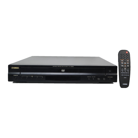
Page 5: Front Panel
DV-C6860 I FRONT PANEL I REAR PANEL I REMOTE CONTROL... -
Page 6: Specifications
DV-C6860 I SPECIFICATIONS G PLAYBACK SYSTEM fs 44.1 kHz 2 Hz- 20 kHz DVD-Video CD/VCD fs 44.1 kHz 2 Hz- 20 kHz Video CD & SVCD Distortion and Noise (1 kHz) 0.0035% G CONNECTIONS PICTURE CD CD-R, CD-RW Y output... -
Page 7: Dimensions
DV-C6860 I DIMENSIONS Unit: mm (inch) 435 (17-1/8”) I INTERNAL VIEW POWER SUPPLY UNIT DVD 5-DISC CHANGER MODULE AV P.C.B. MONO P.C.B. BRACKET FRONT FRONT (2) STANDBY/ON P.C.B. FRONT (1) DISPLAY P.C.B. FRONT (3) OPEN/CLOSE P.C.B. -
Page 8: Repair Notes
DV-C6860 I REPAIR NOTES 1. DVD 5-Disc Changer Module The DVD 5-disc changer module consists of the CM unit and tray ass’y. The DVD 5-disc changer module is supplied as a whole. Neither the CM unit nor tray ass’y can be supplied independently. -
Page 9: Disassembly Procedures
DV-C6860 I DISASSEMBLY PROCEDURES See exploded view for item numbers Mounting Top Cover [240] © Remove 7 screws. [260] (4 on side and 3 rear side) Dismounting © Lift top cover from rear side to remove. Front Panel [101] AV P.C.B [1500] Power Supply Unit [1000] ©... - Page 10 DV-C6860 • Preventive measure for laser diode from electrostatic breakdown 1. Removal of Tray Ass’y Top Cover The tray ass’y cannot be supplied independently. The tray When replacing the MONO Board or DVD 5-disc changer module, solder between lands of the optical pick up P.C.B. to ass’y is contained in DVD 5-disc changer module and supplied...
-
Page 11: Block Diagram
DV-C6860 BLOCK DIAGRAM DVD 5-DISC CHANGER MODULE LD1117 LM317 TL431 TL431 POWER SUPPLY UNIT LM337 VA VD MCLK RstN MUTEA Clock Ref MUTEB Mute AOUTL+ LRCK AOUTL- AUDIO OUT DAC & SCLK AOUTR+ Analog Filter SDATA AOUTR- CS4351 AGND DIGITAL OUT... -
Page 12: Printed Circuit Boards
DV-C6860 PRINTED CIRCUIT BOARDS The first digit of a component indicates the component type. 1xxx : Connector 3xxx : Resistor 5xxx : Coil 7xxx : IC, Transistor, FET FOR INFORMATION ONLY (NO REPLACEMENT PARTS WILL BE AVAILABLE) 2xxx : Capacitor... - Page 13 DV-C6860 The first digit of a component indicates the component type. 1xxx : Connector 3xxx : Resistor 5xxx : Coil 7xxx : IC, Transistor, FET 2xxx : Capacitor 4xxx : SMD jumper 6xxx : Diode 9xxx : Wire jumper MONO (Side B)
- Page 14 DV-C6860 FRONT (1) (Side A)
- Page 15 DV-C6860 FRONT (1) (Side B)
- Page 16 DV-C6860 FRONT (2) STANDBY/ON (Side A)
- Page 17 DV-C6860 FRONT (2) STANDBY/ON (Side B)
- Page 18 DV-C6860 FRONT (3) EJECT/PLAY (Side A)
- Page 19 DV-C6860 FRONT (3) EJECT/PLAY (Side B)
- Page 20 DV-C6860 FRONT (4) AV (Side A)
- Page 21 DV-C6860 FRONT (4) AV (Side B)
-
Page 22: Schematic Diagrams
DV-C6860 SCHEMATIC DIAGRAMS FOR INFORMATION ONLY (NO REPLACEMENT PARTS WILL BE AVAILABLE) MONO (1/4) 3102 DV33 RFV33 7103 5102 5V-standby LD1117 5104 B10B-EH-A 3108 T110 Standby-ON T109 T108 ALRCK/LED_ON T107 T106 TO 1111 of FRONT (1) Board T105 LDO_AV33 VSTB... - Page 23 DV-C6860 1201 B5 3236 H8 T275 I12 1202 E1 3237 I8 T276 I12 1203 I12 3238 I8 T277 I10 1204 I11 3239 H1 T278 I12 100n V2P8 V1P4 5210 2201 B6 3240 H1 T279 I10 MONO (2/4) RFVDD3 2202 B6...
- Page 24 DV-C6860 MONO (3/4) SD33 DV33 SD33 SD33 5301 7301 IS42S16100C1-6TL VDDQ Φ SDRAM 512Kx16x2 SD33 16M-1 DQ10 DQ11 MA10 DQ12 DQ13 DBA0 DQ14 DQ15 DQM0 DWE# LDQM DQM1 DCAS# UDQM DRAS# DCS# SDCKE 3310-1 SDCLK DCS# GNDQ 3310-2 DRAS# RAS#...
- Page 25 DV-C6860 MONO (4/4) 4400 4401 4402 4403 3401 ACLK SACLK HLEM26S-1R T400 3402 IOA21 T401 ALRCK SLRCK T420 MUTE_DAC T402 ASDA 3403 T403 ASCL ABCK SBCLK T404 T405 T406 T407 T408 TO 1505 of FRONT (4) Board T409 T410 Page 30...
-
Page 26: Display Panel
DV-C6860 1111 D3 I123 H3 1112 E3 I124 H3 1113 G3 I125 H3 1114 C12 I126 H3 2101 C4 I127 H3 I128 H3 2102 D4 FRONT (1/5) 2103 D4 I129 H3 DISPLAY PANEL 2104 C11 I130 H3 2105 D12 I131 C6... - Page 27 DV-C6860 1210 D2 1211 C5 1212 C5 1213 C6 FRONT (2/5) Left Key Control 1214 C6 1215 C7 1216 C8 2200 B7 2201 C7 2202 C6 2203 C8 2204 C7 2205 D7 2206 D6 3200 C7 3201 C7 3202 D5...
- Page 28 2304 3302 +5Vstby I300 7300 4300 Yamaha 38kHz (NEC CODE) 2307 TSOP4138YA1 * OPTIONAL * Components having special characteristics are marked Z and must be replaced with parts having specifications equal to those originally installed. * Schematic diagram is subject to change without notice.
- Page 29 DV-C6860 FRONT (4/5) 1400 C1 2492 F8 3475 F7 I419 B8 1401 C2 2493 F8 3476 F5 I421 D7 1402 F8 2494 C5 3477 C3 I422 E7 1403 E8 2495 C6 3478 A4 I423 D8 Audio Out & DC Regulation...
- Page 30 DV-C6860 FRONT (5/5) 1500 A1 3520 C3 6502 C8 1502-A B9 3521 C3 6503 E9 1503 B1 3522 C3 6504 E9 1505 C1 3523 C6 6505 F9 +6Vvid 1506 E9 3524 C6 6506 E2 Video Out 100n 2500 25mA 1507 E3...
-
Page 31: Replacement Parts List
DV-C6860 REPLACEMENT PARTS LIST G EXPLODED VIEW When disassembling, use the special screw driver with tip shape in figure. 2.7 mm 1.7 mm 1002-1 DVD 5-Disc Changer Module 1002 The DVD 5-Disc Changer Module consists of the CM Unit and Tray Ass’y. The DVD 5-Disc Changer Module is supplied as a whole. - Page 32 DV-C6860 G REPLACEMENT PARTS LIST Ref. Part No. Description Remarks Markets DV-C6860 * 101 AAX76560 FRONT PANEL ASS'Y 3141 079 34811 * 101 AAX76550 FRONT PANEL ASS'Y 3141 079 34801 * 107 AAX76510 TRAY COVER 3139 244 09781 * 107...
Need help?
Do you have a question about the DV-C6860 and is the answer not in the manual?
Questions and answers