Table of Contents
Advertisement
^1
USER MANUAL
^2
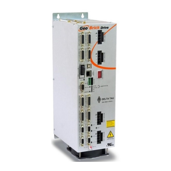
Geo Brick Drive
Single Source Machine Control
21314 Lassen St. Chatsworth, CA 91311 // Tel. (818) 998-2095 Fax. (818) 998-7807 //
^3
^4
^5
..............................................................................
Programmable Servo Amplifier
5xx-603800-xUxx
March 8, 2016
DELTA TAU
Data Systems, Inc.
NEW IDEAS IN MOTION ...
Power // Flexibility // Ease of Use
www.deltatau.com
Advertisement
Table of Contents

Related Manuals for Delta Tau geo brick


Summary of Contents for Delta Tau geo brick
- Page 1 USER MANUAL Geo Brick Drive Programmable Servo Amplifier 5xx-603800-xUxx March 8, 2016 DELTA TAU Data Systems, Inc. NEW IDEAS IN MOTION … ……………………………………………..…...………………. Single Source Machine Control Power // Flexibility // Ease of Use 21314 Lassen St. Chatsworth, CA 91311 // Tel. (818) 998-2095 Fax. (818) 998-7807 //...
- Page 2 All Delta Tau Data Systems, Inc. motion controller, accessory, and amplifier products contain static sensitive components that can be damaged by incorrect handling. When installing or handling Delta Tau Data Systems, Inc. products, avoid contact with highly insulated materials. Only qualified personnel should be allowed to handle this equipment.
- Page 3 Geo Brick Drive User Manual Safety Instructions Qualified personnel must transport, assemble, install, and maintain this equipment. Properly qualified personnel are persons who are familiar with the transport, assembly, installation, and operation of equipment. The qualified personnel must know and observe the following standards and regulations: IEC364resp.CENELEC HD 384 or DIN VDE 0100...
- Page 4 Geo Brick Drive User Manual MANUAL REVISION HISTORY DESCRIPTION DATE CHANGE APPROVED MANUAL REFORMATTING. CORRECTIONS AVAILABLE UPON 8/10/11 REQUEST. CORRECTED Ixx71 FOR QUADRATURE LINEAR 10/10/11 UPDATED +5V ENC PWR SECTION 10/13/11 UPDATED ABSOLUTE SERIAL ENCODER SECTION. GENERAL 4/15/12 UPDATES. - UPDATED PART NUMBER TREE...
-
Page 6: Table Of Contents
Geo Brick Drive Options ......................16 Environmental Specifications ......................17 Protection Specifications ......................17 Agency Approvals ........................17 Electrical Specifications .......................18 4-Axis Geo Brick Drive ........................18 6-Axis Geo Brick Drive ........................18 8-Axis Geo Brick Drive ........................19 RECEIVING AND UNPACKING ..................20 Use of Equipment ........................20 MOUNTING ........................... - Page 7 Geo Brick Drive User Manual Wiring the Digital Inputs and Outputs ....................45 General Purpose I/Os (J6) Suggested M-Variables ................46 General Purpose I/Os Additional (J7) Suggested M-Variables ............46 J8: PWM Amplifier Interface ......................47 J9: Handwheel and Analog I/O ......................48 Setting up the Analog Inputs (J9) ......................
- Page 8 Geo Brick Drive User Manual Yaskawa Sigma II 17-Bit Absolute Encoder ..................131 Yaskawa Sigma III 20-Bit Absolute Encoder ................... 134 Yaskawa Sigma II 13-Bit Incremental Encoder ................137 Yaskawa Sigma II 17-Bit Incremental Encoder ................139 Yaskawa Incremental Encoder Alarm Codes ................... 141 Homing with Yaskawa Incremental Encoders .................
- Page 9 Geo Brick Drive User Manual Commutation Angle, Current Mask: Ixx72, Ixx84................198 PWM Scale Factor: Ixx66....................... 198 Current Feedback Address: Ixx82 ....................198 Commutation Position Address, Commutation Enable: Ixx83, Ixx01 ..........199 Magnetization Current, Slip Gain: Ixx77 ..................199 Motor Slip Gain: Ixx78 ........................199 I2T Protection: Ixx57, Ixx58, Ixx69 ....................
- Page 10 Calculating Motor Current Output Example ................... 268 LED Status ..........................269 Error 18 (Erro18) ........................270 Watchdog Timer Trip......................... 271 Geo Brick Drive Specific Online Commands ................272 Type ............................... 272 Ampversion ............................ 273 Ampmod ............................273 Ampsid ............................274 Ampclrf ............................
- Page 11 Geo Brick Drive User Manual Reloading Boot and Communication Firmware ................280 Reset Switch SW (Factory Reset) ....................281 LIST OF CHANGES AND UPDATES ................282 AMPVER Command, December 2007 ..................282 External Encoder Power Supply Connector, April 2010 ..............283 EEPROM Write-Protect Enable.
-
Page 12: Introduction
IGBT-based drive technology, resulting in a compact, smart 4-, 6- or 8-axis servo drive package. The flexibility of the Turbo PMAC2 enables the Geo Brick to drive Brush, Brushless or AC induction motors with unsurpassed pure digital DSP performance. The absence of analog signals – required for typical motion controller/drive interfacing –... -
Page 13: Downloadable Turbo Pmac Script
P1=0 ; Set P1=0 at download Open PLC 1 Clear ; Open PLC Buffer 1, clear contents CMDP"Geo Brick User Manual Test PLC" ; Send unsolicited response to host port P1=P1+1 ; Counter using variable P1 Disable PLC 1 ; Disable plc 1 Close ;... -
Page 14: Specifications
Geo Brick Drive User Manual SPECIFICATIONS Part Number CPU Options – GBLA-BB-CDD-EFGHHHI0 Axes GBLA-BB-CDD-EFGHHHI0 Turbo PMAC 2 Processor : Four Axes Silver Enclosure : Six Axes Silver Enclosure C0: 80Mhz, 8Kx24 Internal, 256Kx24SRAM, 1MB Flash (Default) : Eight Axes Silver Enclosure... - Page 15 Geo Brick Drive User Manual Communication Options GBLA-BB-CDD-EFGHHHI0 USB2 and Eth100 are included Note: To use PMAC-NC software, DPRAM is required 0xxxxx: No Options, Default Dxxxxx: DPRAM option, size 8K x 16-bit wide Mxxxxx: ModBus Ethernet Communication Protocol (Software) option...
-
Page 16: Geo Brick Drive Options
Geo Brick Drive User Manual Geo Brick Drive Options CPU Options 80MHz Turbo PMAC2 CPU (Standard, default) 8Kx24 internal memory, 256Kx24 SRAM, 1MB flash memory 80MHz Turbo PMAC2 CPU 8Kx24 internal memory, 1Mx24 SRAM, 4MB flash memory ... -
Page 17: Environmental Specifications
Geo Brick Drive User Manual Environmental Specifications Description Specifications 0 to 45°C Operating Temperature Above 40°C,de-rate current output by 2.5% per °C Storage Temperature -25°C to +70°C Humidity 10% to 90% non-condensing ~3300 Feet (1000 m) Operating Altitude De-rate current output by 1.1% per additional 330 feet (100m) Air Flow Clearances ~3 inches (76.2mm) above and below unit for air flow... -
Page 18: Electrical Specifications
Geo Brick Drive User Manual Electrical Specifications 4-Axis Geo Brick Drive GBL4-xx-5xx-xxx xxxxx GBL4-xx-8xx-xxx xxxxx Output Continuous Current (rms/axis) Output Peak Current for 2 seconds (rms/axis) Rated Input Current @240VAC 3-phase(all axes) Max ADC (I T Settings) 16.26A 26.02A Output Power Per Axis [Watts]... -
Page 19: 8-Axis Geo Brick Drive
Geo Brick Drive User Manual 8-Axis Geo Brick Drive GBL8-xx-552 GBL8-xx-882 GBL8-xx-582 GBL8-xx-852 Axes Output Continuous Current (rms/axis) Output Peak Current for 2 sec (rms/axis) Max ADC (I T Settings) 16.26A 16.26A 26.02A 26.02A 16.02A 26.02A 26.02A 16.02A Rated Input Current @240 3-phase(all axes) -
Page 20: Receiving And Unpacking
If the Geo Brick Drive is to be stored for several weeks before use, be sure that it is stored in a location that conforms to published storage humidity and temperature specifications. Use of Equipment The following restrictions will ensure the proper use of the Geo Brick Drive: ... -
Page 21: Mounting
Geo Brick Drive User Manual MOUNTING The location of the Geo Brick Drive is important. Installation should be in an area that is protected from direct sunlight, corrosives, harmful gases or liquids, dust, metallic particles, and other contaminants. Exposure to these can reduce the operating life and degrade performance of the drive. -
Page 22: Connector Locations
AC/DC Alt. Enc. Pwr Bus Power Analog I/O Input Handwheel Bottom View Newer models of the Geo Brick Drive were introduced in October of 2012. They can be recognized by the 4-pin terminal block logic and STO connector. Note Mounting... -
Page 23: 4-Axis Geo Brick Drive
Geo Brick Drive User Manual 4-Axis Geo Brick Drive GBL4-xx-5xx-xxx-xxxx And GBL4-xx-8xx-xxx-xxxx Width Depth Height Weight 114mm/4.50in 178mm/7.00in 391mm/15.40in 4.4Kg/9.6lbs 3.00" (76.20 mm) 14.31" 15.40" (363.52 mm) (391.16 mm) 4 x M4 13.38" (339.73 mm) 7.00" (177.83 mm) 4.50" (114.29 mm) -
Page 24: 6-Axis Geo Brick Drive
Geo Brick Drive User Manual 6-Axis Geo Brick Drive GBL6-xx-5xx-xxx-xxxx And GBL6-xx-8xx-xxx-xxxx Width Depth Height Weight 203mm/8.00in 178mm/7.00in 391mm/15.40in 6.50" (165.10 mm) 14.31" (363.52 mm) 15.40" (391.16 mm) 4 x M4 13.38" (339.73 mm) 8.00" 7.00" (203.20 mm) (177.83 mm) -
Page 25: 8-Axis Geo Brick Drive
Geo Brick Drive User Manual 8-Axis Geo Brick Drive GBL8-xx-552-xxx-xxxx, GBL8-xx-582-xxx-xxxx, GBL8-xx-852-xxx-xxxx, GBL8-xx-882-xxx-xxxx Width Depth Height Weight 203mm/8.00in 178mm/7.00in 392mm/15.40in 9.0 Kg/19.9lbs 6.50" (165.10 mm) 14.31" (363.52 mm) 15.40" (391.16 mm) 4 x M4 13.38" (339.73 mm) 8.00" 7.00" (203.20 mm) (177.83 mm) -
Page 26: Pinouts And Software Setup
WARNING regulations pertaining to the installation. J1: Main Bus Power Input J1 is used to bring the main AC/DC bus power into the Geo Brick Drive. J1: Molex 4-pin Male Mating: Molex 4-pin Female Pin #... -
Page 27: Power On/Off Sequence
Main bus power should NEVER be applied or cycled if the 24V logic power is NOT applied. Caution Newer and older Geo Brick Drives differ in the delay restrictions between main power cycles. The newer models were introduced in October of 2012. They can be recognized by the 4-pin terminal block 24V logic with STO connector. - Page 28 Older Models of the Geo Brick Drive With the older models of the Geo Brick Drives, cycling main bus power must obey the following warning restrictions. A delay should be inserted in either software, hardware or both to ensure that these restrictions are conformed.
-
Page 29: Recommended Main Bus Power Wiring/Protection
Caution Grounding, Bonding System grounding is crucial for proper performance of the Geo Brick Drive. Panel wiring requires that a central earth-ground (also known as ground bus bar) location be installed at one part of the panel. The ground bus bar is usually a copper plate directly bonded to the back panel. This electrical ground connection allows for each device within the enclosure to have a separate wire brought back to the central earth-ground. - Page 30 Geo Brick Drive User Manual Three-Phase Main AC Power Wiring Diagram 3-PHASE TRANSFORMER 110-240 VAC PROTECTION EARTH EMC/EMI MAGNETIC FILTER CONTACTOR Shielded Phase-Phase Twisted Voltage Suppressors Single-Phase Main AC Power Wiring Diagram Single Phase Source 110-240 VAC DELTA TAU DATA SYSTEMS,...
- Page 31 GBL6-xx-5xx GBL8-xx-582 GBL6-xx-8xx GBL8-xx-852 Specific applications fuse sizing can be done using the following equations. Take, as an example, a 4-axis Geo Brick (5/10A) on 240VAC bus, and driving 4 motors (5A continuous current rating): √ DC Bus Voltage: [VDC]...
- Page 32 Bus Power Cables The Geo Brick Drive electronics create a DC bus by rectifying the incoming AC lines. The current flow into the drive is not sinusoidal but rather a series of narrow, high-peak pulses. Keeping the incoming impedance small is essential for not hindering these current pulses.
-
Page 33: J2: 24Vdc Logic Power And Safe Torque Off (Sto)
J2, in the newer models of the Geo Brick Drive, is also used to wire the Safe Torque Off (STO) input. The STO allows the complete (hardware) disconnection of the power amplifiers from the motors. This mechanism prevents unintentional “movement of”... -
Page 34: Older Models
Mating: Molex 2-pin Male +24VDC Molex Mating Connector p/n: 0436450200 Molex Pins p/n: 0430300008 Molex Crimper Tool p/n: 11-01-0185 Delta Tau Mating Connector p/n: 014-043645-200 (for internal use) Delta Tau pins p/n: 014-043030-008 (for internal use) Pin # Symbol Function... -
Page 35: Disabling The Sto (Backward Compatibility)
Geo Brick Drive User Manual Disabling the STO (Backward compatibility) Disabling the STO maintains full backward compatibility with existing systems, pre-STO installations. This is done by simply tying STO IN (pin #1) to +24V (pin #3): STO IN STO OUT... -
Page 36: J3: External Shunt Resistor
The GAR10 and GAR15 resistors are designed to drain excess bus energy very quickly. The 4- and 8-axis Geo Brick Drives are designed for operation with external shunt resistors of 15 Ohms, 6-axis units requiring 10 Ohms. Delta Tau provides these resistors with pre-terminated cables that plug directly into connector J3. - Page 37 Newer models of the Geo Brick Drive incorporate an internal shunt resistor rated at 300W, 100-Ohms. Note Newer models of the Geo Brick Drive were introduced in October of 2012. They can be recognized by the 4-pin terminal block logic and STO connector.
-
Page 38: J4: Limits, Flags, Equ [Axis 1- 4]
- EQU To avoid machine/equipment damage and before applying power or connecting any of the flags; make sure that your electrical design/wiring is in accordance with the Geo Brick Drive’s part number option for 5- or 24-volt connection Caution J4: D-sub DB-25F... -
Page 39: J5: Limits, Flags, Equ [Axis 5- 8]
- EQU To avoid machine/equipment damage and before applying power or connecting any of the flags; make sure that your electrical design/wiring is in accordance with the Geo Brick Drive’s part number option (5- or 24-volts) Caution J5: D-sub DB-25F... -
Page 40: Wiring The Limits And Flags
Geo Brick Drive User Manual Wiring the Limits and Flags The Geo Brick Drive’s limits and flags can be wired to be either sinking or sourcing. The opto-isolator IC used is a PS2705-4NEC-ND quad phototransistor output type. This IC allows the current to flow from return to flag or from flag to return. -
Page 41: Limits And Flags [Axis 1- 4] Suggested M-Variables
Geo Brick Drive User Manual Limits and Flags [Axis 1- 4] Suggested M-Variables M115->X:$078000,19 ; User 1 flag input status M116->X:$078000,9 ; EQU1, ENC1 compare output value M120->X:$078000,16 ; Home flag 1 input status M121->X:$078000,17 ; Positive Limit 1 flag input status M122->X:$078000,18... -
Page 42: J6: General Purpose Inputs/Outputs
Geo Brick Drive User Manual J6: General Purpose Inputs/Outputs J6 is used to wire general purpose digital inputs/outputs to the Geo Brick Drive. J6: D-sub DC-37F Mating: D-sub DC-37M Pin # Symbol Function Description GPI1 Input Input 1 GPI3 Input... -
Page 43: J7: General Purpose Inputs/Outputs (Additional)
Geo Brick Drive User Manual J7: General Purpose Inputs/Outputs (Additional) J7 is used to wire the additional (optional) general purpose digital Inputs/Outputs to the Geo Brick. J7: D-sub DC-37F Mating: D-sub DC-37M Pin # Symbol Function Description GPI17 Input Input 17... -
Page 44: About The Digital Inputs And Outputs
They are rated to a maximum current of 500 mA, and are overload protected. The outputs, in the newer models of the Geo Brick Drive (control board 603793-10A and later), use the PS2701-1NEC photocoupler. They are protected with a ZXMS6006DG; an enhancement mode MOSFET - diode incorporated. -
Page 45: Wiring The Digital Inputs And Outputs
Geo Brick Drive User Manual Wiring the Digital Inputs and Outputs The inputs and outputs can be wired to be either sourcing out of or sinking into the Geo Brick Drive: Sourcing Inputs / Outputs Sinking Inputs / Outputs 12 - 24 VDC... -
Page 46: General Purpose I/Os (J6) Suggested M-Variables
Geo Brick Drive User Manual General Purpose I/Os (J6) Suggested M-Variables // Inputs: M1->Y:$78800,0,1 ; Input 01 J6 Pin#1 M2->Y:$78800,1,1 ; Input 02 J6 Pin#20 M3->Y:$78800,2,1 ; Input 03 J6 Pin#2 M4->Y:$78800,3,1 ; Input 04 J6 Pin#21 M5->Y:$78800,4,1 ; Input 05 J6 Pin#3 M6->Y:$78800,5,1... -
Page 47: J8: Pwm Amplifier Interface
Geo Brick Drive User Manual J8: PWM Amplifier Interface J8 is used to connect to third party PWM amplifiers. This is a limited option, contact technical support for setup details. Pinouts and Software Setup... -
Page 48: J9: Handwheel And Analog I/O
Geo Brick Drive User Manual J9: Handwheel and Analog I/O J9 is used to wire the additional analog inputs, handwheel encoder, analog output, and PFM output. J9: D-sub DB-25F Mating: D-sub DB-25M Pin # Symbol Function Notes AIN1 Input Analog Input #1... -
Page 49: Setting Up The Analog Inputs (J9)
Geo Brick Drive User Manual Setting up the Analog Inputs (J9) ±10VDC Input Signals The J9 port can be used to bring in eight AGND ADC1 multiplexed 12-bit single-ended analog inputs using the traditional Option 12. AGND ADC2 AGND ADC3... - Page 50 Geo Brick Drive User Manual J9 Analog Inputs Suggested M-Variables Bipolar Mode (Signed) Unipolar Mode (Unsigned) M6991->Y:$003400,12,12,S ; ADC1 M6991->Y:$003400,12,12,U ; ADC1 M6992->Y:$003402,12,12,S ; ADC2 M6992->Y:$003402,12,12,U ; ADC2 M6993->Y:$003404,12,12,S ; ADC3 M6993->Y:$003404,12,12,U ; ADC3 M6994->Y:$003406,12,12,S ; ADC4 M6994->Y:$003406,12,12,U ; ADC4 M6995->Y:$003408,12,12,S ;...
-
Page 51: Setting Up The Analog Output (J9)
Geo Brick Drive User Manual Setting up the Analog Output (J9) Differential Output Single-Ended Output DAC Output Analog ±10VDC DAC+ DAC Output Analog Device ±10VDC Device DAC- The analog output out of J9 is a (12-bit) filtered PWM signal, therefore a PWM frequency in the range of 30-36 KHz and a PWM deadtime of zero are suggested for a good quality analog output signal (minimum ripple). - Page 52 PWM frequency, or should not be used at all. Note For Help with clock calculations, download the Delta Tau Calculator: DT Calculator Forum Link J9 Analog Output Suggested M-Variable // I/O 10 & 11 Mode (PWM) M7051->Y:$78404,10,1...
-
Page 53: Setting Up Pulse And Direction Output Pfm (J9)
FREQUENCY AMPLIFIER DEVICE/ DIR+ AMPLIFIER DIR- Using the Delta Tau Calculator or referring to the Turbo Software Reference Manual, the desired maximum PFM Frequency and pulse width can be chosen. DT Calculator Step2 Step1 Results Step 1: Choose Max PFM clock by changing the PFM clock divider. Click on calculate to see results. - Page 54 Geo Brick Drive User Manual The output frequency control Ixx69 specifies the maximum command output value that corresponds to the maximum PFM Frequency. I6826=3 ; MACRO IC Channel2 Output Mode Select. C PFM M8000->Y:$7841C,8,16,S ; Supplementary Channel 2* Output C Command Value ;...
-
Page 55: Setting Up The Handwheel Port (J9)
Geo Brick Drive User Manual Setting up the Handwheel Port (J9) A quadrature encoder type device is normally brought into the handwheel port; it can be wired and used in either single-ended or differential mode. The encoder power is not provided for this device, it must be brought in externally. -
Page 56: X1-X8: Encoder Feedback, Digital A Quad B
Note The standard encoder inputs on the Geo Brick Drive are designed for differential quadrature type signals. Quadrature encoders provide two digital signals to determine the position of the motor. Each nominally with 50% duty cycle, and nominally 1/4 cycle apart. - Page 57 Geo Brick Drive User Manual Channel A Channel B Typically, these signals are 5V TTL/CMOS level whether they are single-ended or differential. Differential signals can enhance noise immunity by providing common mode noise rejection. Modern design standards virtually mandate their use in industrial systems.
-
Page 58: Setting Up Quadrature Encoders
; Channels 1-8 activated Encoder Count Error (Mxx18) The Geo Brick Drive has an encoder count error detection feature. If both the A and B channels of the quadrature encoder change state at the decode circuitry (post-filter) in the same hardware sampling clock (SCLK) cycle, an unrecoverable error to the counter value will result (lost counts). -
Page 59: Encoder Loss Detection, Quadrature
Kill of the motor/encoder in question is strongly advised. Caution No automatic firmware (Geo Brick) action is taken upon detection of encoder(s) loss; it is the user’s responsibility to perform the necessary action to make the application safe under these conditions, see example PLC below. - Page 60 Encoder Loss Example PLC: A 4-axis Geo Brick is setup to kill all motors upon the detection of one or more encoder loss. In addition, it does not allow enabling any of the motors when an encoder loss condition has been encountered:...
-
Page 61: Step And Direction Pfm Output (To External Stepper Amplifier)
Geo Brick Drive User Manual Step and Direction PFM Output (To External Stepper Amplifier) The Geo Brick Drive has the capability of generating step and direction (Pulse Frequency Modulation) output signals to external stepper amplifiers. These signals are accessible at the encoder connectors. The step and direction outputs are RS422 compatible and could be connected in either differential or single- ended configuration for 5V (input signal) amplifiers. - Page 62 Geo Brick Drive User Manual Using the Delta Tau Calculator or referring to the Turbo Software Reference Manual, the desired maximum PFM Frequency and pulse width can be chosen. DT Calculator Step2 Step1 Results Step 1: Choose Max PFM clock by changing the PFM clock divider. Press calculate to see results.
- Page 63 Geo Brick Drive User Manual The position-Loop PID Gains can be calculated using the following equations: // Position-Loop PID Gains: I530,4,100=11190 ; Motors 5-8 Proportional Gain I531,4,100=0 ; Motors 5-8 Derivative Gain I532,4,100=15038 ; Motors 5-8 Velocity FeedForward Gain I533,4,100=0 ;...
-
Page 64: X1-X8: Encoder Feedback, Sinusoidal
T Hall Unused This option allows the Geo Brick Drive to interface directly to up to eight sinusoidal feedback devices. The high resolution interpolator circuitry accepts inputs from sinusoidal or quasi-sinusoidal encoders (1- Volt peak to peak) and provides encoder position data. It creates 4,096 steps per sine-wave cycle. -
Page 65: Setting Up Sinusoidal Encoders
Geo Brick Drive User Manual Setting up Sinusoidal Encoders The Sinusoidal position feedback is set up through the Encoder Conversion Table (ECT) as a high resolution interpolation entry. Encoder Conversion Table Setup Example, Channel 1 1. Conversion Type: High res. interpolator, PMAC2 Style 2. -
Page 66: Counts Per User Units
Geo Brick Drive User Manual The equivalent Turbo PMAC script code for 8-channel entries // Channel 1 I8000=$FF8000 ; High resolution interpolator I8001=$078B00 ; A/D converter address I8002=$000000 ; Bias Term and Entry result // Channel 2 I8003=$FF8008 ; High resolution interpolator I8004=$078B02 ;... -
Page 67: Encoder Count Error (Mxx18)
Geo Brick Drive User Manual Encoder Count Error (Mxx18) The Geo Brick Drive has an encoder count error detection feature. If both the A and B channels of the quadrature encoder change state at the decode circuitry (post-filter) in the same hardware sampling clock (SCLK) cycle, an unrecoverable error to the counter value will result (lost counts). -
Page 68: Encoder Loss Detection, Sinusoidal
Kill of the motor/encoder in question is strongly advised. Caution No automatic firmware (Geo Brick) action is taken upon detection of encoder(s) loss; it is the user’s responsibility to perform the necessary action to make the application safe under these conditions. Killing the motor/encoder in question is the safest action possible, and strongly recommended to avoid a runaway, and machine damage. -
Page 69: X1-X8: Encoder Feedback, Resolver
Geo Brick Drive User Manual X1-X8: Encoder Feedback, Resolver X1-X8: D-sub DA-15F Mating: D-sub DA-15M Pin # Symbol Function Notes Sin+ Input Sine+ Cos+ Input Cosine+ CHC+ Input Index+ EncPwr Output Encoder Power 5 Volts Unused Unused 2.5 Volts Output Reference Power 2.5 volts... -
Page 70: Resolver Excitation Magnitude
Geo Brick Drive User Manual Resolver Excitation Magnitude Revolvers’ excitation magnitude is a global setting used for all available Resolver channels. It has 15 possible settings: #define ResExcMag M8000 ; Resolver Excitation Magnitude MACRO definition ResExcMag->Y:$78B11,0,4 ; Resolver Excitation Magnitude register... - Page 71 Geo Brick Drive User Manual Resolver Data Registers The Resolver raw data is found in the Resolver Data registers Channel Register Channel Register Y:$78B00 Y:$78B08 Y:$78B02 Y:$78B0A Y:$78B04 Y:$78B0C Y:$78B06 Y:$78B0E Encoder Conversion Table Processing A dedicated 3-line Encoder Conversion Table entry is used for Resolver feedback.
- Page 72 Geo Brick Drive User Manual Calculating The Tracking Filter Gains The tracking filter gains are system dependent, and need to be fine-tuned. This can be done by gathering and plotting filtered versus unfiltered data while moving the motor shaft manually. Best case scenario is super-imposing the filtered data on top of the unfiltered with minimum ripple and overshoot.
- Page 73 Geo Brick Drive User Manual I8041=$478B10 ; Excitation address I8042=$000000 ; SIN/COS Bias word I8043=$D8352B ; Tracking filter from conversion location $352B I8044=$400 ; Maximum change in counts/cycle I8045=$80000 ; Proportional gain I8046=$0 ; Reserved setup word I8047=$1 ; Integral gain...
- Page 74 Geo Brick Drive User Manual Resolver Power-On PLC Example Setting up a resolver with 10V excitation magnitude and 10 KHz excitation frequency: // Clock Settings: 10KHz Phase & Servo I7100=5895 ; Servo IC1 I7101=0 I7102=0 I6800=5895 ; MACRO IC0 I6801=0...
-
Page 75: X1-X8: Encoder Feedback, Hiperface
Geo Brick Drive User Manual X1-X8: Encoder Feedback, HiperFace The majority of HiperFace devices requires 7-12VDC power. This has to be supplied externally and NOT wired into the brick unit. Pins#4 and #12 are unused in this case, leave floating. -
Page 76: Setting Up Hiperface On-Going Position
Geo Brick Drive User Manual Setting up HiperFace On-Going Position The HiperFace on-going position is set up through the Encoder Conversion Table as a high resolution interpolation entry Encoder Conversion Table Setup Example, Channel 1 1. Conversion Type: High res. interpolator, PMAC2 Style 2. - Page 77 Geo Brick Drive User Manual And the equivalent Turbo PMAC code for setting up all 8 channels: // Channel 1 I8000=$FF8000 ; High resolution interpolator entry, $78000 I8001=$078B00 ; A/D converter address, $78B00 I8002=$000000 ; Bias Term and Entry result at $3503...
-
Page 78: Setting Up Hiperface Absolute Power-On Position
Geo Brick Drive User Manual Setting up HiperFace Absolute Power-On Position Setting up the absolute position read with HiperFace requires the programming of two essential control registers: Global Control Registers Channel Control Registers The resulting data is found in: ... - Page 79 Geo Brick Drive User Manual Global Control Registers X:$78BnF (default value: $812004) where n=2 for axes 1-4 n=3 for axes 5-8 Global Control Register Axes 1-4 X:$78B2F Axes 5-8 X:$78B3F The Global Control register is used to program the serial encoder interface clock frequency SER_Clock and configure the serial encoder interface trigger clock.
- Page 80 Reserved Reserved and always reads zero. This bit field is normally used to define the encoder address Encoder transmitted with each command. Delta Tau does not support [07:00] 0xFF address multiple encoders per channel; a value of $FF sends a general broadcast.
- Page 81 Geo Brick Drive User Manual HiperFace Data Registers The HiperFace absolute power-on data is conveyed into 4 memory locations; Serial Encoder Data A, B, C, and D. The Serial Encoder Data A register holds the 24 bits of the encoder position data. If the data exceeds the 24 available bits in this register, the upper overflow bits are LSB justified and readable in the Serial Encoder Data B, which also holds status and error bits.
-
Page 82: Setting Up Hiperface Encoders Example
Geo Brick Drive User Manual Setting up HiperFace Encoders Example An 8-axis Geo Brick Drive is connected to eight HiperFace encoders, serial data is programmed to 9600 (M=129, N=2) baud rate for all eight channels: =0 Rising Edge =1 Falling Edge... - Page 83 Geo Brick Drive User Manual The Global and Channel Control registers have to be initialized on power-up. Following, is an example PLC showing the initialization of all eight channels: //=========================== NOTES ABOUT THIS PLC EXAMPLE ================================// // This PLC example utilizes: - M5990 through M5999...
- Page 84 Geo Brick Drive User Manual Channels 1 through 4 are driving HiperFace encoders with 12-bit (4096) single-turn resolution and 12- bit (4096) multi-turn resolution for a total number of data bits of 24 (12+12). The entire data stream is held in the HiperFace serial data A register:...
- Page 85 Geo Brick Drive User Manual #define Ch4STRes P7006 #define Ch4MTRes P7007 #define Ch5STRes P7008 #define Ch5MTRes P7009 #define Ch6STRes P7010 #define Ch6MTRes P7011 #define Ch7STRes P7012 #define Ch7MTRes P7013 #define Ch8STRes P7014 #define Ch8MTRes P7015 Ch1STRes=12 Ch1MTRes=12 ; Ch1 Multi Turn and Single Turn Resolutions --User Input...
- Page 86 Geo Brick Drive User Manual STData=0 MTData=0 If (STRes!>24) ; Single Turn Res<=24 //===========SINGLE TURN DATA===========// Two2STDec=exp(STRes*ln(2)) Two2STHex=Two2STDec-1 STData=SerialRegA&Two2STHex //===========MULTI TURN DATA============// Two2MTDec=exp(MTRes*ln(2)) Two2MTHex=Two2MTDec-1 If (MTRes=0) LowerMTBits=0 UpperMTBits=0 Two2MTDec=0 Two2MTHex=0 MTData=0 Else LowerMTBits=24-STRes STTemp1=exp(LowerMTBits*ln(2)) STTemp2=0 UpperMTBits=MTRes-LowerMTBits MTTemp1=exp(LowerMTBits*ln(2)) MTTemp2=exp(UpperMTBits*ln(2)) Temp1=(SerialRegA/Two2STDec)&(MTTemp1-1) Temp2=SerialRegB&(MTTemp2-1)
-
Page 87: Encoder Count Error (Mxx18)
Geo Brick Drive User Manual Encoder Count Error (Mxx18) The Geo Brick Drive has an encoder count error detection feature. If both the A and B channels of the quadrature encoder change state at the decode circuitry (post-filter) in the same hardware sampling clock (SCLK) cycle, an unrecoverable error to the counter value will result (lost counts). -
Page 88: Encoder Loss Detection, Hiperface
Kill of the motor/encoder in question is strongly advised. Caution No automatic firmware (Geo Brick) action is taken upon detection of encoder(s) loss; it is the user’s responsibility to perform the necessary action to make the application safe under these conditions. Killing the motor/encoder in question is the safest action possible, and strongly recommended to avoid a runaway, and machine damage. -
Page 89: X1-X8: Encoder Feedback, Ssi
Geo Brick Drive User Manual X1-X8: Encoder Feedback, SSI X1-X8: D-sub DA-15F Mating: D-sub DA-15M Pin # Symbol Function Notes Unused Unused Unused EncPwr Output Encoder Power 5 Volts only Data- Input Data- packet Clock- Output Serial Encoder Clock- Unused... - Page 90 Geo Brick Drive User Manual Global Control Registers X:$78BnF (Default value: $630002) where: n=2 for axes 1-4 n=3 for axes 5-8 Global Control Register Axes 1-4 X:$78B2F Axes 5-8 X:$78B3F The Global Control register is used to program the serial encoder interface clock frequency SER_Clock and configure the serial encoder interface trigger clock.
- Page 91 Geo Brick Drive User Manual Channel Control Registers X:$78Bn0, X:$78Bn4, X:$78Bn8, X:$78BnC where: n=2 for axes 1-4 n=3 for axes 5-8 Channel 1 X:$78B20 Channel 5 X:$78B30 Channel 2 X:$78B24 Channel 6 X:$78B34 Channel 3 X:$78B28 Channel 7 X:$78B38 Channel 4 X:$78B2C Channel 8 X:$78B3C Each channel has its own Serial Encoder Command Control Register defining functionality parameters.
- Page 92 Geo Brick Drive User Manual SSI Data Registers The SSI data is conveyed into 4 memory locations; Serial Encoder Data A, B, C, and D. The Serial Encoder Data A register holds the 24 bits of the encoder position data. If the data exceeds the 24 available bits in this register, the upper overflow bits are LSB justified and readable in the Serial Encoder Data B, which also holds the parity error flag.
-
Page 93: Ssi Control Registers Setup Example
Geo Brick Drive User Manual SSI Control Registers Setup Example Channel 1 is driving a 25-bit (13-bit Singleturn, 12-bit Multiturn) SSI encoder. The encoder outputs binary data with no parity, and requires a 1 MHz serial clock. Global Control Register... - Page 94 Geo Brick Drive User Manual Field Value Notes Channel Control Word Parity Type Hex 0x00 Trigger Mode Continuous trigger (typical) Trigger Enable Enable $001419 Gray / Binary Binary Data Ready / Senc Mode =1 Enable serial driver Protocol Bits Hex 0x19...
-
Page 95: X1-X8: Encoder Feedback, Endat 2.1/2.2
Geo Brick Drive User Manual X1-X8: Encoder Feedback, EnDat 2.1/2.2 X1-X8: D-sub DA-15F Mating: D-Sub DA-15M Pin # Symbol Function Notes Unused Unused Unused EncPwr Output Encoder Power 5 Volts Data- Input Data- packet Clock- Output Serial Encoder Clock- Unused... - Page 96 Geo Brick Drive User Manual Global Control Registers X:$78BnF (default value: $002003) where n=2 for axes 1-4 n=3 for axes 5-8 Global Control Register Axes 1-4 X:$78B2F Axes 5-8 X:$78B3F The Global Control register is used to program the serial encoder interface clock frequency. SENC_CLK is the serial data clock transmitted from the Brick to the encoder.
- Page 97 Geo Brick Drive User Manual Channel Control Registers X:$78Bn0, X:$78Bn4, X:$78Bn8, X:$78BnC where: n=2 for axes 1-4 n=3 for axes 5-8 Channel 1 X:$78B20 Channel 5 X:$78B30 Channel 2 X:$78B24 Channel 6 X:$78B34 Channel 3 X:$78B28 Channel 7 X:$78B38 Channel 4 X:$78B2C Channel 8 X:$78B3C Each channel has its own Serial Encoder Command Control Register defining functionality parameters.
- Page 98 Geo Brick Drive User Manual EnDat Data Registers The EnDat data is conveyed into 4 memory locations; EnDat Data A, B, C, and D. The EnDat Data A register holds the 24 bits of the encoder position data. If the data exceeds the 24 available bits in this register, the upper overflow bits are LSB justified and readable in the EnDat Data B register, which also holds error flags.
-
Page 99: Endat Control Registers Setup Example
Geo Brick Drive User Manual EnDat Control Registers Setup Example Channel 1 is driving a 37-bit (25-bit Singleturn, 12-bit Multiturn) EnDat 2.2 encoder. The encoder requires a 4 MHz serial clock. Global Control Register The Global Control register is a 24-bit hexadecimal word which is set up as follows:... - Page 100 Geo Brick Drive User Manual Field Value Notes Channel Control Word Command code =$38 Hex 0x38 for EnDat 2.2 only Trigger Mode Continuous trigger (typical) Trigger Enable Enable $381425 Data Ready / Senc Mode =1 Enable serial driver Protocol Bits...
-
Page 101: X1-X8: Encoder Feedback, Biss C/B
Geo Brick Drive User Manual X1-X8: Encoder Feedback, BiSS C/B X1-X8: D-sub DA-15F Mating: D-Sub DA-15M Pin # Symbol Function Notes Unused Unused Unused EncPwr Output Encoder Power 5 Volts Data- Input/Output Data- packet, SLO- Clock- Output Serial Encoder Clock-, MO-... - Page 102 Geo Brick Drive User Manual Global Control Registers X:$78BnF (default value: $18000B) where n=2 for axes 1-4 n=3 for axes 5-8 Global Control Register Axes 1-4 X:$78B2F Axes 5-8 X:$78B3F The Global Control register is used to program the serial encoder interface clock frequency SER_Clock and configure the serial encoder interface trigger clock.
- Page 103 Geo Brick Drive User Manual Channel Control Registers X:$78Bn0, X:$78Bn4, X:$78Bn8, X:$78BnC where: n=2 for axes 1-4 n=3 for axes 5-8 Channel 1 X:$78B20 Channel 5 X:$78B30 Channel 2 X:$78B24 Channel 6 X:$78B34 Channel 3 X:$78B28 Channel 7 X:$78B38 Channel 4 X:$78B2C Channel 8 X:$78B3C Each channel has its own Serial Encoder Command Control Register defining functionality parameters.
- Page 104 Geo Brick Drive User Manual This write-only bit is used to enable the output drivers for SENC_MODE the SENC_SDO, SENC_CLK, SENC_ENA pins for each respective channel. [09] Reserved Reserved and always reads zero. This bit field is used to define the number of status bits in the encoder data.
-
Page 105: Biss Control Registers Setup Example
Geo Brick Drive User Manual BiSS Control Registers Setup Example Channel 1 is driving an 18-bit Renishaw resolute BiSS-C encoder. The encoder requires a 1 MHz serial clock, and has 2 status bits. Global Control Register The Global Control register is a 24-bit hexadecimal word which is set up as follows:... - Page 106 Geo Brick Drive User Manual Field Value Notes Channel Control Word CRC Mask Hex 0x21 typical for Renishaw BiSS Type for BiSS-C Trigger Mode Continuous trigger (typical) Trigger Enable Enable $211492 Data Ready / Senc Mode =1 Enable serial driver...
-
Page 107: Setting Up Ssi | Endat | Biss
This technique processes the data for position similarly to Technique 1, but it requires a dedicated ECT entry for commutation. Some applications may require deviating from the suggested setup methods (e.g. extremely high resolution and speed requirements). Contact Delta Tau for assistance with these special cases. Note Pinouts and Software Setup... -
Page 108: Setup Summary
Special considerations should be made if the Singleturn (ST) and Multiturn (MT) data bits are NOT contiguous (in consecutive fields). Contact Delta Tau for assistance with these special cases. Note Multiturn MT is equal to zero for encoders which do not possess Multiturn data bits. - Page 109 Geo Brick Drive User Manual Resolution Scale Factor (SF) Parameter Encoder Type Technique 1/3 Technique 2 Rotary ST-5 [counts/rev] Resolution Scale Factor SF Linear = 1/RES = 1/(32*RES) [counts/user units] Where ST: is the rotary encoder Singleturn resolution in bits RES: is the linear scale resolution, in user units (e.g.
-
Page 110: Technique 1 Example
Geo Brick Drive User Manual Technique 1 Example Channel 1 is driving a 25-bit (13-bit Singleturn, 12-bit Multiturn) rotary serial encoder, or a linear scale with similar protocol resolution (13 bits, 1 micron). Encoder Conversion Table - for position (Technique 1) ... - Page 111 Geo Brick Drive User Manual Counts Per User Units (Technique 1) With technique 1, the user should expect to see 2 counts per revolution for rotary encoders, and 1/Resolution counts per user unit for linear scales in the motor position window.
- Page 112 Geo Brick Drive User Manual In this mode, PMAC reads and reports 18 bits from the first serial data register: Serial Data Register B Serial Data Register A (Ch1 Y:$78B21) (Ch1 Y:$78B20) 18 bits With this setting of Ixx80=2, the actual position is reported automatically on Power-up. Otherwise, a #1$* command is necessary to read and report the absolute position.
-
Page 113: Technique 2 Example
Geo Brick Drive User Manual Technique 2 Example Channel 1 is driving a 37-bit (25-bit Singleturn, 12-bit Multiturn) rotary serial encoder, or a linear scale with similar protocol resolution (25 bits, 10 nanometer). Encoder Conversion Table – for position (Technique 2) ... - Page 114 Geo Brick Drive User Manual At this point, you should be able to move the motor/encoder shaft by hand and see ‘motor’ counts in the position window Note Counts Per User Units (Technique 2) ST-5 With technique 2, the user should expect to see 2 /32 counts per revolution for rotary encoders, and 1/(32*Resolution) counts per user unit for linear scales in the motor position window.
- Page 115 Geo Brick Drive User Manual Encoder Conversion Table - for commutation (Technique 2) Commutation with Turbo PMAC does not require high resolution data. With Technique 2, it is recommended to fix it at 18 bits. This will also eliminate quantization noise.
- Page 116 Geo Brick Drive User Manual Absolute Power-On Position Read (Technique 2) With technique 2, the absolute power-on position can be read directly from the serial data registers. But, proper scaling (5-bit right shift, in a PLC) is required to conform to the unshifted on-going position.
- Page 117 Geo Brick Drive User Manual With absolute serial encoders (no multi-turn data), the power-on position format is set up for unsigned operation. Note The upper two fields in Ixx95 are the only relevant ones. Bits 0 through 15 are reserved and should always be set to 0.
-
Page 118: Technique 3 Example
Geo Brick Drive User Manual Technique 3 Example Channel 1 is driving a 32-bit (20-bit Singleturn, 12-bit Multiturn) rotary serial encoder, or a linear scale with similar protocol resolution (20 bits, 0.1 micron). Encoder Conversion Table - for position (Technique 3) ... - Page 119 Geo Brick Drive User Manual At this point, you should be able to move the motor/encoder shaft by hand and see ‘motor’ counts in the position window. Note Counts Per User Units (Technique 3) With technique 3, the user should expect to see 2 counts per revolution for rotary encoders, and 1/Resolution counts per user unit for linear scales in the motor position window.
- Page 120 Geo Brick Drive User Manual Encoder Conversion Table - for commutation (Technique 3) Commutation with Turbo PMAC does not require high resolution data. With Technique 3, it is recommended to fix it at 18 bits. This will also eliminate quantization noise.
- Page 121 Geo Brick Drive User Manual Absolute Power-On Position Read (Technique 3) With Technique 3, the absolute power-on read can be performed using PMAC’s automatic settings (Ixx80, Ixx10 and Ixx95). Example 1: Channel 1 driving a 32-bit (20-bit single turn, 12-bit multi-turn) rotary serial encoder: I180=2 ;...
- Page 122 Geo Brick Drive User Manual With absolute serial encoders (no multi-turn data), the power-on position format is set up for unsigned operation. Note The upper two fields in Ixx95 are the only relevant ones. Bits 0 through 15 are reserved and should always be set to 0.
-
Page 123: X1-X8: Encoder Feedback, Yaskawa Sigma Ii & Iii
Geo Brick Drive User Manual X1-X8: Encoder Feedback, Yaskawa Sigma II & III X1-X8: D-sub DA-15F Mating: D-sub DA-15M Pin # Symbol Function Notes EncPwr Output Encoder Power 5 Volts Input Serial Data In Common Common Ground Output Serial Data Out... - Page 124 Geo Brick Drive User Manual Molex 2.00 mm (.079") Pitch Serial I/O Connector, Receptacle Kit, Wire-to-Wire. Part Number: 0542800609 Pin # Function Wire Color code +5VDC BLACK BAT+ Orange BAT- Orange/Black (Orange/White) Blue Blue/Black (Blue/White) All Yaskawa Sigma II & Sigma III protocols, whether incremental or absolute and regardless of the resolution, are supported.
- Page 125 Geo Brick Drive User Manual Global Control Registers X:$78BnF (default value: $002003) where n=2 for axes 1-4 n=3 for axes 5-8 Global Control Register Axes 1-4 X:$78B2F Axes 5-8 X:$78B3F With the Yaskawa option, the Global Control Register is pre-set and need not be changed.
- Page 126 Geo Brick Drive User Manual Channel Control Registers X:$78Bn0, X:$78Bn4, X:$78Bn8, X:$78BnC where: n=2 for axes 1-4 n=3 for axes 5-8 Channel 1 X:$78B20 Channel 5 X:$78B20 Channel 2 X:$78B24 Channel 6 X:$78B34 Channel 3 X:$78B28 Channel 7 X:$78B38 Channel 4 X:$78B2C Channel 8 X:$78B3C Bits 10, 12, and 13 are the only fields to be configured in the Channel Control Registers with the Yaskawa option.
- Page 127 Geo Brick Drive User Manual Yaskawa Feedback Channel Control Power-On Example PLC (Motors 1-8) This code statement can be added to your existing initialization PLC. Open PLC 1 clear CMD"WX:$78B20,$1400" CMD"WX:$78B24,$1400" CMD"WX:$78B28,$1400" CMD"WX:$78B2C,$1400" CMD"WX:$78B30,$1400" CMD"WX:$78B34,$1400" CMD"WX:$78B38,$1400" CMD"WX:$78B3C,$1400" Disable plc 1...
-
Page 128: Yaskawa Sigma Ii 16-Bit Absolute Encoder
Geo Brick Drive User Manual Yaskawa Sigma II 16-Bit Absolute Encoder Y:$78B21 Y:$78B20 [23-12] [11-0] [23-20] [19-4] [3:0] Multi-Turn Position Absolute Single Turn Data (16-bits) (16-bits) Yaskawa Data Registers Channel 1 Y:$78B20 Channel 5 Y:$78B30 Channel 2 Y:$78B24 Channel 6... - Page 129 Geo Brick Drive User Manual I8006=$278B2C ; Entry 4 Unfiltered parallel pos of location Y:$78B2C I8007=$020004 ; Width and Bias, total of 32-bits LSB starting at bit#4 I8008=$278B30 ; Entry 5 Unfiltered parallel pos of location Y:$78B30 I8009=$020004 ; Width and Bias, total of 32-bits LSB starting at bit#4 I8010=$278B34 ;...
- Page 130 Geo Brick Drive User Manual Absolute Power-On Position Read (Yaskawa 16-bit) Channel 1 example PLC, 16-bit Absolute Sigma II Encoder End Gat Del Gat Close #define STD0_15 M7000 ; Single-turn Data 0-15 (16-bits) #define MTD0_3 M7001 ; Multi-Turn Data 0-3 (4-bits)
-
Page 131: Yaskawa Sigma Ii 17-Bit Absolute Encoder
Geo Brick Drive User Manual Yaskawa Sigma II 17-Bit Absolute Encoder Y:$78B21 Y:$78B20 [23-13] [12-0] [23-21] [20-4] [3:0] Multi-Turn Position Absolute Single Turn Data (16-bits) (17-bits) Yaskawa Data Registers Channel 1 Y:$78B20 Channel 5 Y:$78B30 Channel 2 Y:$78B24 Channel 6... - Page 132 Geo Brick Drive User Manual Encoder Conversion Table Setup (Motors 1-8) The ECT automatic entry is equivalent to: I8000=$278B20 ; Entry 1 Unfiltered parallel pos of location Y:$78B20 I8001=$021004 ; Width and Bias, total of 33-bits LSB starting at bit#4 I8002=$278B24 ;...
- Page 133 Geo Brick Drive User Manual Absolute Power-On Position Read (Yaskawa 17-bit) Channel 1 example PLC, 17-bit Absolute Sigma II Encoder End Gat Del Gat Close #define FirstWord M7000 ; Yaskawa Data Register1, 1 word #define SecondWord M7001 ; Yaskawa Data Register1, 2...
-
Page 134: Yaskawa Sigma Iii 20-Bit Absolute Encoder
Geo Brick Drive User Manual Yaskawa Sigma III 20-Bit Absolute Encoder Y:$78B21 Y:$78B20 [23-16] [15-0] [23-4] [3:0] Multi-Turn Position Absolute Single Turn Data (16-bits) (20-bits) Yaskawa Data Registers Channel 1 Y:$78B20 Channel 5 Y:$78B30 Channel 2 Y:$78B24 Channel 6 Y:$78B34... - Page 135 Geo Brick Drive User Manual Encoder Conversion Table Setup (Motors 1-8) The ECT automatic entry is equivalent to: I8000=$278B20 ; Entry 1 Unfiltered parallel pos of location Y:$78B20 I8001=$024004 ; Width and Bias, total of 36-bits LSB starting at bit#4 I8002=$278B24 ;...
- Page 136 Geo Brick Drive User Manual Absolute Power-On Position Read (Yaskawa 20-bit) Channel 1 example PLC, 20-bit Absolute Sigma III Encoder End Gat Del Gat Close #define FirstWord M1000 ; Yaskawa Data Register1, 1 word #define SecondWord M1001 ; Yaskawa Data Register1, 2...
-
Page 137: Yaskawa Sigma Ii 13-Bit Incremental Encoder
Geo Brick Drive User Manual Yaskawa Sigma II 13-Bit Incremental Encoder Y:$78B21 Y:$78B20 [23-11] [10-0] [22-11] [10:4] Incremental Position in Incremental Compensation Single Turn (11-bits) (13-bits) Yaskawa Data Registers Channel 1 Y:$78B20 Channel 5 Y:$78B30 Channel 2 Y:$78B24 Channel 6 Y:$78B34... - Page 138 Geo Brick Drive User Manual Encoder Conversion Table Setup (Motors 1-8) The ECT automatic entry is equivalent to: I8000=$278B20 ; Entry 1 Unfiltered parallel pos of location Y:$78B20 I8001=$00D006 ; Width and Bias, total of 13-bits LSB starting at bit#6 I8002=$278B24 ;...
-
Page 139: Yaskawa Sigma Ii 17-Bit Incremental Encoder
Geo Brick Drive User Manual Yaskawa Sigma II 17-Bit Incremental Encoder Y:$78B21 Y:$78B20 [23-11] [10-0] [22-6] [5:4] Incremental Position in Incremental Compensation Single Turn (11-bits) (17-bits) Yaskawa Data Registers Channel 1 Y:$78B20 Channel 5 Y:$78B30 Channel 2 Y:$78B24 Channel 6 Y:$78B34... - Page 140 Geo Brick Drive User Manual Encoder Conversion Table Setup (Motors 1-8) The ECT automatic entry is equivalent to: I8000=$278B20 ; Entry 1 Unfiltered parallel pos of location Y:$78B20 I8001=$011006 ; Width and Bias, total of 17-bits LSB starting at bit#6 I8002=$278B24 ;...
-
Page 141: Yaskawa Incremental Encoder Alarm Codes
Geo Brick Drive User Manual Yaskawa Incremental Encoder Alarm Codes Yaskawa Incremental encoder Alarm Registers Channel 1 Y:$78B22,8,8 Channel 5 Y:$78B32,8,8 Channel 2 Y:$78B26,8,8 Channel 6 Y:$78B36,8,8 Channel 3 Y:$78B2A,8,8 Channel 7 Y:$78B3A,8,8 Channel 4 Y:$78B2E,8,8 Channel 8 Y:$78B3E,8,8 Alarm... -
Page 142: Homing With Yaskawa Incremental Encoders
Geo Brick Drive User Manual Homing with Yaskawa Incremental Encoders Hardware capture is not available with serial data encoders, software capture (Ixx97=1) is required. Setting Ixx97 to 1 tells Turbo PMAC to use the register whose address is specified by Ixx03 for the trigger position. -
Page 143: X9-X10: Analog Inputs/Outputs
Geo Brick Drive User Manual X9-X10: Analog Inputs/Outputs X9-X10: D-Sub DE-9F Mating: D-Sub DE-9M Pin # Symbol Function Notes AGND Ground Analog Ground ADC+ Input 16-bit Analog Input, channel 5/6+ DAC+ Output 12-bit filtered PWM analog output, channel 5/6+ BR-NC... -
Page 144: Setting Up The Analog (Adc) Inputs
Geo Brick Drive User Manual Setting up the Analog (ADC) Inputs Differential Analog Input Signal Single Ended Analog Input Signal AGND AGND ADC+ ADC+ ±10VDC ADC- Input Signal ±10VDC Input Signal For single-ended connections, tie the negative ADC pin to ground. - Page 145 Geo Brick Drive User Manual Analog Inputs Suggested M-Variables With 4-axis units, the ADC strobe word of Servo IC 1 should be set to $1FFFFF. And the analog inputs can be accessed directly through these M-Variable assignments: I7106=$1FFFFF ; Servo IC 1 ADC Strobe Word M505->Y:$078105,8,16,S...
-
Page 146: Setting Up The Analog (Dac) Outputs
Geo Brick Drive User Manual Setting up the Analog (DAC) Outputs Differential DAC Output Signal Single Ended DAC Output Signal AGND AGND DAC+ DAC+ Analog DAC- Device Analog Device The analog outputs on X9 through X12 are (12-bit) filtered PWM signals, therefore a PWM frequency in the range of 30-40 KHz and a PWM deadtime of zero are suggested for a good quality analog output signal (minimized ripple). - Page 147 PWM frequency, or not used at all. Note For Help with clock settings, use the Delta Tau Calculator: DT Calculator Forum Link Analog Outputs Suggested M-Variables:...
-
Page 148: Setting Up The General Purpose Relay, Brake
Geo Brick Drive User Manual Setting up the General Purpose Relay, Brake This option provides either a general purpose relay (which can be toggled in software) OR a dedicated brake relay output tied to its’ corresponding channel amplifier-enable line. This option is built to order and is jumper configurable at the factory (E6, E7, E8 and E9). - Page 149 Geo Brick Drive User Manual High True Brake Output Sourcing Sinking DC Power Supply DC Power Supply 12-24VDC 12-24V BRAKE BRAKE RET Logic device / Logic device / Brake Brake BRAKE RET BRAKE Low True Brake Output Sourcing Sinking DC Power Supply...
-
Page 150: Setting Up The External Amplifier Fault Input
Geo Brick Drive User Manual Setting up the External Amplifier Fault Input The amplifier fault minus signal is internally tied to the brake/relay common (pin #8). Caution The amplifier fault signal is a bidirectional single-ended input. Its’ minus end is tied internally to the brake/relay common (pin #8) which dictates how the amplifier fault input should be connected. -
Page 151: X13: Usb 2.0 Connection
Geo Brick and PC side. Note If the electrical ground planes of the host PC and the Geo Brick Drive are not at the same level (e.g. laptop on battery) then the use of an industrial USB hub is highly advised. -
Page 152: X15: Watchdog And Abort (Tb2)
Geo Brick Drive User Manual X15: Watchdog and ABORT (TB2) X15 has two essential functions: A 24VDC Abort Input (mandatory for normal operation) which can be used in various applications to halt motion when necessary (i.e. opening machine door, replacing tool). -
Page 153: Wiring The Watchdog Output
Geo Brick Drive User Manual Killed axes are not affected by the triggering of the abort. They do not get enabled (unlike the software abort command). Note There are no software configurable parameters to enable or disable the hardware Abort Input functionality. -
Page 154: Rs232: Serial Communication Port
PMAC ready bit The baud rate for the RS-232 serial port is set by variable I54. At power-up reset, The Geo Brick Drive sets the active baud based on the setting of I54 and the CPU speed I52. Note that the baud rate frequency is divided down from the CPU’s operational frequency. -
Page 155: A1 - A8: Motor Wiring
Molex Mating Connector p/n: 0428160412 Molex Pins p/n: 0428150031 Molex Crimper Tool p/n: 63811-1500 Delta Tau Mating Connector p/n: 014-H00F04-049 (for internal use) Delta Tau Pins p/n: 014-042815-031 (for internal use) Low and medium power axes use smaller connectors than the high power axes. -
Page 156: Motor Cable, Noise Elimination
The connection between the cable shield and the motor frame should be as short as possible). At the Geo Brick Drive end, make a 360 degree connection between the shield and the provided studs or grounded chassis (protection earth) at the M4 mounting screws. - Page 157 If the grounding/shielding techniques are insufficient, you may install chokes in the motor phases at the Geo Brick Drive end such as wrapping individual motor leads several times through a ferrite core ring. DigiKey, Micro-Metals (T400-26D), Fair Rite (2643540002), or equivalent ferrite cores are recommended.
-
Page 158: Motor Selection
Geo Brick Drive User Manual Motor Selection The Geo Brick Drive interfaces with a wide variety of motors. It supports virtually any kind of three- phase AC/DC rotary, linear brushless, or induction motors. Using two out of the three phases, it is also possible to drive permanent magnet DC brush motors. - Page 159 Geo Brick Drive User Manual Required Bus Voltage for Speed and Torque For a required motor Speed, and continuous Torque, the minimum DC Bus Voltage (V ) can be estimated by looking at the equivalent single phase circuit: BEMF Motor...
-
Page 160: Enc Pwr (Alternate Encoder Power)
~ 0.5A (+5V power). This alters the total power available for encoders. The newer models of the Geo Brick Drive have a stronger power supply which can handle more (+5V) power drain. The following tables summarize the +5V power available for encoder devices (X1-X8): The maximum current draw out of a single encoder channel must not exceed 750 mA. -
Page 161: Wiring The Alternate (+5V) Encoder Power
Power Supply A jumper tying pins 1 and 2 is the default configuration. This is the configuration with which the Geo Brick Drive is shipped to a customer. Note The controller (PMAC) 5V logic is independent of this scheme, so if no encoder power is provided the PMAC will remain powered-up (provided the standard 24 volts is brought in). -
Page 162: Functionality, Safety Measures
Power sequence: encoders versus controller/drive It is highly recommended to power up the encoders before applying power to the Geo Brick Drive Encoder Power Loss (i.e. power supply failure, loose wire/connector) The Geo Brick Drive, with certain feedback devices, can be setup to read absolute position or perform phasing on power-up (either automatic firmware functions, or user PLCs). -
Page 163: Motor Setup
Motor Setup Flow Chart The following, is a comprehensive diagram showing the basic steps to follow for successfully setting up a motor with the Geo Brick Drive: Encoder / Motor wiring Factory Default Reset $$$***, Save, $$$ (recommended) Encoder Software Setup. -
Page 164: Dominant Clock Settings
Note Recommended clock Frequencies The default clock settings in the Geo Brick Drive should work fine for the majority of applications, they are set as follows: Phase Clock: 9.000 KHz PWM Clock: 4.500 KHz... - Page 165 Geo Brick Drive User Manual Hardware Clock: The hardware clock is directly related to sampling rates of encoders, digital /analog converters, and pulse frequency modulation PFM clock. With the Geo Brick Drive, the hardware clock setting (I7m03) is mostly used to set PFM clock frequencies.
-
Page 166: Adc Strobe Word (I7M06)
MaxPhaseFreq=117964.8/(2*I7000+3) PWMClk=117964.8/(4*I7000+6) PhaseClk=MaxPhaseFreq/(I7001+1) ServoClk=PhaseClk/(I7002+1) ADC Strobe Word (I7m06) In normal mode operation (see also enhanced mode section), the ADC Strobe word(s) on a Geo Brick Drive should be set to $3FFFFF. I7106=$3FFFFF ; Servo IC 1 ADC Strobe Word I7006=$3FFFFF ;... -
Page 167: Ac/Dc Brushless (Rotary/Linear) Motor Setup
Commutation Angle, Current Mask: Ixx72, Ixx84 I172,8,100=1365 ; Motors 1-8 Commutation phase angle (Geo Brick Drive specific) I184,8,100=$FFF000 ; Motors 1-8 Current-Loop Feedback Mask Word (Geo Brick Drive specific) PWM Scale Factor: Ixx66 If Motor Rated Voltage > Bus Voltage: I166=1.10*I7000 ;... -
Page 168: Commutation Position Address, Commutation Enable: Ixx83, Ixx01
Geo Brick Drive User Manual Commutation Position Address, Commutation Enable: Ixx83, Ixx01 Quadrature / Sinusoidal / HiperFace For these types of feedback devices, it is recommended to use the quadrature data for commutation. And Ixx01 should be equal to 1, indicating commutation from an X-register: I183=$078001 ;... - Page 169 Geo Brick Drive User Manual Resolver With resolvers, it is recommended to use the unfiltered data processed in the Encoder Conversion Table: // these addresses can differ depending on the encoder conversion table management I183=$3503 ; Motor 1 On-going Commutation Position Address I283=$350B ;...
-
Page 170: I2T Protection: Ixx57, Ixx58, Ixx69
Brick Drive and motor are chosen to setup I2T protection. If the peak current limit chosen is that of the Geo Brick Drive (possible values 10, 16, or 30 Amps) then the time allowed at peak current is set to 2 seconds. -
Page 171: Commutation Cycle Size: Ixx70, Ixx71
Geo Brick Drive User Manual Commutation Cycle Size: Ixx70, Ixx71 The ratio of Ixx70/Ixx71 represents the number of encoder counts per electrical cycle. These parameters are typically set up with respect to the motor, encoder type, resolution, and processing method:... -
Page 172: Adc Offsets: Ixx29, Ixx79
Geo Brick Drive User Manual The Singleturn (ST) data bits for rotary encoders, as well as the serial protocol bit-length for linear scales can be found in the encoder manufacturer’s spec sheet. Note The Electrical Cycle Length (ECL) or pole-pair pitch (in user units) can be found in the motor manufacturer’s spec sheet. -
Page 173: Current-Loop Tuning: Ixx61, Ixx62, Ixx76
Geo Brick Drive User Manual Current-Loop Tuning: Ixx61, Ixx62, Ixx76 The current-loop tuning is done as in any Turbo PMAC digital current loop setup. The PMACTuningPro2 automatic or interactive utility can be used to fine-tune the Current-Loop. An acceptable Current-Loop... -
Page 174: Motor Phasing, Power-On Mode: Ixx73, Ixx74, Ixx80, Ixx81, Ixx91
Geo Brick Drive User Manual Motor Phasing, Power-On Mode: Ixx73, Ixx74, Ixx80, Ixx81, Ixx91 The Geo Brick Drive supports a variety of phasing procedures for commutated (brushless) motors. This section discusses the following phasing methods: Manual | Custom Phasing ... - Page 175 Geo Brick Drive User Manual Manual | Custom Phasing Manual phasing can be used with virtually any type of feedback. It is ideal for: Quick Phasing Troubleshooting phasing difficulties Finding a “good” phase finding output value to use in the 2-guess or stepper phasing Manual phasing consists of locking the motor tightly onto one of its phases, then zeroing the phase position register (suggested M-Variable Mxx71).
- Page 176 Geo Brick Drive User Manual Alternately, a more refined manual phasing method can be implemented. Knowing a good value which would lock the motors onto a phase (using the above procedure), the following example locks (in small incremental steps) the motor onto one phase then steps it back into the other phase:...
- Page 177 Geo Brick Drive User Manual 2-Guess Phasing Method The 2-guess is a rough phasing method for motors with relatively small loads. It is not ideal for high torque requirements. It can be used with any type of feedback. Example of typical settings: Ixx73=1200 ;...
- Page 178 The Geo Brick Drive supports the conventional 120° spacing hall sensors’ type, each nominally with 50% duty cycle, and nominally 1/3 cycle apart. The Geo Brick Drive has no automatic hardware or software features to work with 60° spacing. The 120° spacing format provides six distinct states per cycle:...
- Page 179 Geo Brick Drive User Manual Plotting the phase position (Mxx71) Plotting the hall sensors (Mxx28) The scale factor is used to scale the phase position $700000 Masking enables reading W, V, and U to 0 - 360°. It is = 360 / Ixx71 in bits 20, 21, and 22 respectively 5.
- Page 180 Geo Brick Drive User Manual With positive movement of the motor, if the halls state transition is from 1 to 3 (as seen in the example plot) then use the following set of equations: I181=$78000 ; Channel 1 power-on phase address (see table below) #define HallsTrans1_3 M7025 ;...
- Page 181 Geo Brick Drive User Manual Fine Phasing Correcting for hall sensors’ error (torque loss) can be implemented using the following procedure (performed once per installation): 1. Phase the motor manually (as tight as possible). See manual phasing section. 2. Home motor to machine zero location (e.g. most commonly using flag and C-index), with or without home offset, similarly to how the motor would home after the machine has been commissioned.
- Page 182 Geo Brick Drive User Manual Hall Effect Phasing: Yaskawa Incremental encoders Hall-effect sensors can be used for rough phasing on power-up without the need for a phasing search move. This initial phasing provides reasonable torque. With a hall sensors’ error of about ±30° resulting a loss in torque of about 15%, it will need to be corrected for top operation.
- Page 183 Geo Brick Drive User Manual #define Ch1YasIncBits0_3 M127 ; Channel 1 Yaskawa Inc. Data (first 4 bits) #define Ch2YasIncBits0_3 M227 ; Channel 2 Yaskawa Inc. Data (first 4 bits) #define Ch3YasIncBits0_3 M327 ; Channel 3 Yaskawa Inc. Data (first 4 bits)
- Page 184 Geo Brick Drive User Manual Example: Channel 1 is driving a Yaskawa Incremental Encoder, with the test procedure above resulting in zone-1 definitions. Halls power-on phasing can be done in a PLC as follows: #define Ch1IncData M7030 #define Ch1Halls M7031 Ch1IncData->Y:$78B20,0,24...
- Page 185 Geo Brick Drive User Manual Absolute Power-On Phasing: HiperFace With HiperFace, the absolute serial data can be used to establish a phase reference position on power-up without moving the motor. A custom PLC is suggested for reading the absolute power-on position directly from the raw serial HiperFace data registers.
- Page 186 Geo Brick Drive User Manual Absolute Power-On Channel# 8 7 6 5 4 3 2 1 Phasing, channels ChPhaseSel (Binary) 0 0 0 0 1 1 1 1 => ChPhaseSel =$0F 1 through 4 ChPhaseSel (Hex) Absolute Power-On Channel# 8 7 6 5 4 3 2 1 Phasing, channels ChPhaseSel (Binary) 0 1 0 1 0 1 0 1 =>...
- Page 187 Geo Brick Drive User Manual Ixx08=108+(ChNo-1)*100 Mxx71=171+(ChNo-1)*100 PhaseErrBit=148+(ChNo-1)*100 I5111= 100*8388608/I10 while(I5111>0) endw // Compute position offset from user force phase test input PhaseOffset=P(PhaseTest)%P(MtrSF) PhaseOffset=PhaseOffset*I(Ixx70) PhaseOffset=PhaseOffset%I(Ixx71) I5111= 100*8388608/I10 while(I5111>0) endw // Compute present phase position PresPhasePos=M(ActPos)/(I(Ixx08)*32) PresPhasePos=PresPhasePos%P(MtrSF) PresPhasePos=PresPhasePos*I(Ixx70) PresPhasePos=PresPhasePos%I(Ixx71) I5111= 100*8388608/I10 while(I5111>0) endw...
- Page 188 Geo Brick Drive User Manual Absolute Power-On Phasing: EnDat | SSI | BiSS With absolute serial encoders, the absolute serial data can be used to establish a phase reference position on power-up without moving the motor or executing a phase search move.
- Page 189 Geo Brick Drive User Manual Finding the Phase Offset The phase offset is found experimentally by performing a one-time phase force test on an uncoupled/unloaded (preferably) motor: 1. Read/update the absolute position (must be read correctly for the phasing to work).
- Page 190 Geo Brick Drive User Manual Setting up Ixx91, the power-on phase position format: Technique 1 Technique 2/3 (Ixx01=1) For Ixx01= 3 For Ixx01= 1 = Unsigned, Y-register = Unsigned, X-register, = Unsigned, X-register, ST bits (ST + 5bit-shift) bits 18 bits...
- Page 191 Geo Brick Drive User Manual Setting up Ixx75, the phase position offset The Phase position offset is set up using the following equation: Where: PhaseOffset is the recorded value (found earlier) from the phase force test. In this mode, and upon issuing a #n$ command, PMAC will compute the correct phase position then close the loop on the motor (motor must be tuned to hold position).
- Page 192 Geo Brick Drive User Manual Absolute Power-On Phasing: Yaskawa absolute encoders With absolute encoders, the single turn data is used to find an absolute phase position offset per electrical cycle thus an absolute phase reference position. Prior to implementing a power-on phasing routine you should try and...
- Page 193 Geo Brick Drive User Manual Absolute Power-On Phasing Example PLCs (Yaskawa): With the motor phase position offset established, the phase position register can now be modified on power-up to compensate for the calculated offset. This allows the user to issue jog commands or close the loop and run a motion program on power-up or reset.
-
Page 194: Open-Loop Test, Encoder Decode: I7Mn0
Geo Brick Drive User Manual Open-Loop Test, Encoder Decode: I7mn0 Having phased the motor successfully, it is now possible to execute an open loop test. The open-loop test is critical to verify that the direction sense of the encoder is the same as the command output. - Page 195 With Absolute Serial Encoders (EnDat, SSI, BiSS, Yaskawa): The Geo Brick Drive has no control on the direction sense of the serial data stream. There are no software parameters that allow this change. Normally, the direction sense is set by jumpers or software at the encoder side.
-
Page 196: Position-Loop Pid Tuning: Ixx30
Geo Brick Drive User Manual Position-Loop PID Tuning: Ixx30…Ixx39 The position-loop tuning is done as in any Turbo PMAC PID-Loop setup. The PMACTuningPro2 automatic or interactive utility can be used for fine tuning. Remember to perform an Open Loop Test after phasing and before trying to close the loop on the motor to make sure that the encoder decode (I7mn0) is correct. -
Page 197: High Speed Motors
Geo Brick Drive User Manual High Speed Motors With Geo Brick Drives, motors conceived to operate at higher speeds (e.g. greater than 15,000 rpm) require the implementation of commutation delay compensation Ixx56. This is also known as phase advance. It only applies to motors commutated (synchronous or asynchronous) by PMAC. -
Page 198: Ac Induction (Asynchronous) Motor Setup - With Encoder
; Motor #4 PWM Scale Factor. Set to 10% above PWM Count. If Bus Voltage > Motor Rated Voltage: A Geo Brick Drive connected to 3-Phase 230 VAC Bus, driving a 110 VAC Induction Motor. In this case, Ixx66 serves as a voltage limit for the motor I466=1.10*I7000*Mtr4Voltage/ACBusVoltage... -
Page 199: Commutation Position Address, Commutation Enable: Ixx83, Ixx01
Geo Brick Drive User Manual Commutation Position Address, Commutation Enable: Ixx83, Ixx01 Digital Quadrature Feedback (Default) I483=$078019 ; Motor #4 On-going Commutation Position Address I401=1 ; Motor #4 Commutation Enabled, from X-register AC Induction Motors are not generally used for (high precision) positioning;... -
Page 200: I2T Protection: Ixx57, Ixx58, Ixx69
Brick Drive and motor are chosen to setup I2T protection. If the peak current limit chosen is that of the Geo Brick Drive (possible values 10, 16, or 30 Amps) then the time allowed at peak current is set to 2 seconds. -
Page 201: Commutation Cycle Size: Ixx70, Ixx71
Geo Brick Drive User Manual Commutation Cycle Size: Ixx70, Ixx71 The ratio of Ixx70/Ixx71 represents the number of encoder counts per electrical cycle. For an AC Induction Motor, we will limit the explanation for digital quadrature feedback devices since they are the most widely used for this type of motor. -
Page 202: Open-Loop Test, Encoder Decode: I7Mn0
Geo Brick Drive User Manual Open-Loop Test, Encoder Decode: I7mn0 Having calculated the Slip Gain Ixx78 and performed a satisfactory current-loop tuning, an open-loop test can now be performed to verify the direction sense of the encoder counting versus the command output. - Page 203 Geo Brick Drive User Manual Automatic Open-loop test, 20% magnitude and 300 milliseconds move time, showing incorrect encoder decode. AC Induction Motors, with incorrect encoder decode, generally show erratic data in the Open- Loop test (as opposed to a nice inverted saw-tooth shape curve with DC Brushless motors). In either cases, I7mn0 for motor #4 (i.e.
-
Page 204: Position-Loop Pid Tuning: Ixx30
Geo Brick Drive User Manual Position-Loop PID Tuning: Ixx30…Ixx39 The position-loop tuning is done as in any Turbo PMAC PID-Loop setup. The PMACTuningPro2 automatic or interactive utility can be used for tuning. 2000 counts (~1/2 rev) Step Move for 1000 milliseconds (1 sec) -
Page 205: Optimizing Magnetization Current Ixx77, Slip Gain Ixx78
Geo Brick Drive User Manual Optimizing Magnetization Current Ixx77, Slip Gain Ixx78 Magnetization current During the optimization procedure, the motor will rotate up to its maximum velocity. Make sure that motor well mounted/clamped and uncoupled from any rotating inertia. Always be ready to issue a Kill if the motor exceeds its maximum Caution specified speed. - Page 206 Geo Brick Drive User Manual Ixx77 Optimization Procedure: Issue a 25% Open Loop Command (i.e. #4O25) and monitor the motor velocity in the position window (scaled to rpm). The motor should reach and run steadily at a speed that is less than or equal to the motor base speed.
-
Page 207: Correcting I2T Settings
Geo Brick Drive User Manual Optimization procedure (optional): Gather velocity versus time data while issuing an open loop command (i.e. #4O25) Increase the slip gain gradually (small increments~0.00001) until you reach a satisfactory rise time. Of course, the time constant of the motor should not be violated. -
Page 208: Field Weakening
Geo Brick Drive User Manual Field Weakening Field weakening consists of decreasing the stator current component (lowering the magnetization current Ixx77) in order to allow AC induction motors to achieve speeds superior to the specified base speed (name plate). The lower the magnetization current, the higher is the speed that can be achieved. -
Page 209: High Speed Spindles
Geo Brick Drive User Manual High Speed Spindles With Geo Brick Drives, spindles conceived to operate at higher speeds (e.g. greater than 15,000 rpm) require the implementation of commutation delay compensation Ixx56. This is also known as phase advance. It only applies to motors commutated by PMAC. -
Page 210: Ac Induction (Asynchronous) Motor Setup - Without Encoder, Direct Micro-Stepping
Before you start The AC Induction Motor Setup section is conceived for Motor#4, which is most commonly used in Geo Brick Drive applications as a Spindle. Parameters with comments ending with -User Input require the user to enter information pertaining to their system/hardware. -
Page 211: Motor Activation, Position, Velocity Pointers: Ixx03, Ixx04
; Motor #4 PWM Scale Factor. Set to 10% above PWM Count. If Bus Voltage > Motor Rated Voltage: A Geo Brick Drive connected to 3-Phase 230 VAC Bus, driving a 110 VAC Induction Motor. In this case, Ixx66 serves as a voltage limit for the motor #define BusInput ;... -
Page 212: Maximum Achievable Motor Speed, Output Command Limit: Ixx69
Geo Brick Drive User Manual Maximum Achievable Motor Speed, Output Command Limit: Ixx69 In Micro-Stepping, the maximum achievable speed is proportional to the Servo clock and electrical cycle length. A faster Servo Clock results in higher achievable motor speeds. The smaller value of the Theoretical versus Calculated output command limit Ixx69 is chosen. -
Page 213: I2T Protection, Magnetization Current: Ixx57, Ixx58, Ixx69, Ixx77
Brick Drive and motor are chosen to setup I2T protection. If the peak current limit chosen is that of the Geo Brick Drive (possible values 10, 16, or 30 Amps) then the time allowed at peak current is set to 2 seconds. -
Page 214: Motor Slip Gain: Ixx78
Geo Brick Drive User Manual Motor Slip Gain: Ixx78 Ixx78 controls the relationship between the torque command and the slip frequency of magnetic field on the rotor of an AC Induction (Asynchronous) motor. While it is usually set experimentally, The Motor Slip Gain Ixx78 can be calculated either from Motor Name Plate, or Rotor Time Constant. -
Page 215: Current-Loop Tuning: Ixx61, Ixx62, Ixx76
Geo Brick Drive User Manual Current-Loop Tuning: Ixx61, Ixx62, Ixx76 The current-loop tuning is done as in any Turbo PMAC digital current loop setup. The PMACTuningPro2 automatic or interactive utility can be used to fine-tune the Current-Loop. An acceptable Current-Loop... -
Page 216: Moving The Motor
Geo Brick Drive User Manual Moving the Motor In Direct Micro-Stepping of AC Induction motors, the pseudo closed-loop allows the use of Jog commands for positioning, rotating at a pre-specified speed, or indefinite rotation in either direction. In this mode, the AC Induction motor is commanded exactly the same as a DC Brushless (Servo) motor. -
Page 217: Dc Brush Motor Setup
Commutation Enable, Phase Angle, Current Mask: Ixx01, Ixx72, Ixx84 I101,8,100=1 ; Motors 1-8 Commutation enabled I172,8,100=1536 ; Motors 1-8 Commutation phase angle (Geo Brick Drive specific) I184,8,100=$FFF000 ; Motors 1-8 Current-Loop Feedback Mask Word (Geo Brick Drive specific) Motor Setup... -
Page 218: Pwm Scale Factor: Ixx66
Geo Brick Drive User Manual PWM Scale Factor: Ixx66 If Motor Rated Voltage > Bus Voltage: I166=1.10*I7000 ; Motor #4 PWM Scale Factor. Set to 10% above PWM Count. I266=I166 I366=I166 I466=I166 I566=I166 ; Assuming same motor(s) as motor #1 I666=I166 I766=I166 I866=I166 ;... -
Page 219: I2T Protection: Ixx57, Ixx58, Ixx69
Brick Drive and motor are chosen to setup I2T protection. If the peak current limit chosen is that of the Geo Brick Drive (possible values 10, 16, or 30 Amps) then the time allowed at peak current is set to 2 seconds. -
Page 220: Adc Offsets: Ixx29, Ixx79
Geo Brick Drive User Manual ADC Offsets: Ixx29, Ixx79 The ADC offsets importance may vary from one system to another, depending on the motor(s) type and application requirements. They can be left at default of zero especially if a motor setup is to be reproduced on multiple machines by copying the configuration file of the first time integration. -
Page 221: Position-Loop Pid Gains: Ixx30
Geo Brick Drive User Manual Position-Loop PID Gains: Ixx30…Ixx39 The position-loop tuning is done as in any Turbo PMAC PID-Loop setup. The PMACTuningPro2 automatic or interactive utility can be used to fine-tune the PID-Loop. Acceptable Step and Parabolic position responses would look like:... -
Page 222: Macro Connectivity
MACRO stands for Motion and Control Ring Optical. It is a high bandwidth non-proprietary digital interface industrialized by Delta Tau Data Systems for distributed multi-axis systems. MACRO can be connected using either fiber optic or twisted copper pair RJ45 cables. The RJ45 electrical interface can extend to up to 30 meters (or about 100 feet), and the fiber optic interface can extend to up to 3 kilometers (or about 2 miles). -
Page 223: Macro Configuration Examples
Geo MACRO Drive(s) MACRO Slave Notice that the Geo Brick Drive can be either a Master or a Slave in a MACRO Ring. Whenever the Geo Brick Drive is a slave, the MACRO configuration is called MACRO auxiliary. This is a designation which was implemented in the firmware for the Brick family of controllers. -
Page 224: Review: Macro Nodes And Addressing
Geo Brick Drive User Manual Review: MACRO Nodes and Addressing Each MACRO IC consists of 16 nodes: 2 auxiliary, 8 servo and 6 I/O nodes: Auxiliary nodes are reserved for master/slave setting and internal firmware use Servo nodes are used for motor control carrying feedback, commands, and flag information ... -
Page 225: Review: Macro Auxiliary Commands
Geo Brick Drive User Manual Review: MACRO Auxiliary Commands In MACRO Auxiliary mode (Brick-Brick), master and slave data exchange (i.e. reads, writes) can be done using Macro Auxiliary MX commands. For simplicity, the following examples describe syntax commands intended to communicate with a slave unit associated with node 0. -
Page 226: Configuration Example 1: Brick - Brick
Geo Brick Drive User Manual Configuration Example 1: Brick - Brick MACRO Ring Master MACRO Ring Slave This configuration supports two modes: Torque Mode: Most commonly used and highly recommended due to setup simplicity and computational load sharing between Master and Slave. -
Page 227: Setting Up The Slave In Torque Mode
Geo Brick Drive User Manual Setting up the Slave in Torque Mode 1. Establish communication to Slave unit using USB, Ethernet, or Serial. 2. Consider starting from factory default settings. This can be done by issuing a $$$*** followed by a Save, and a $$$. - Page 228 Geo Brick Drive User Manual 8. MACRO ring settings I80, I81 and I82 enable the ring error check function. I85 specifies a station number which the slave unit is assigned to (e.g. multiple slave stations). I6840 specifies whether this is a master or a slave.
- Page 229 Geo Brick Drive User Manual The slave motors should be phased before setting Ixx44. This can be done through a handshaking PLC and using MACRO auxiliary MX commands to trigger the phase routine. Slave Handshaking PLC Example: Phase then kill Motor #1: M133->X:$0000B0,13,1...
-
Page 230: Setting Up The Master In Torque Mode
8. Activating MACRO motors, Flag Control The master Geo Brick Drive can be fitted with 1 or 2 servo ICs to service local channels (4 or 8). The next available channel will be the first macro/slave motor. This allows taking advantage of some of the default MACRO settings set by the firmware upon detecting a MACRO IC. - Page 231 Geo Brick Drive User Manual 9. Position And Velocity Pointers If all local motors have digital quadrature encoders (1-line ECT entries), and no other entries are used in the Encoder Conversion Table then the position (Ixx03) and Velocity (Ixx04) pointers of the...
- Page 232 Geo Brick Drive User Manual Servo Node Addresses MACRO Register MACRO Address Register Motor # Address Motor # motor motor 5 or 9 $78420 Servo Node 0 9 or 13 $78430 Servo Node 8 6 or 10 $78424 Servo Node 1...
-
Page 233: Setting Up The Slave In Pwm Mode
Geo Brick Drive User Manual Setting up the Slave in PWM Mode 1. Establish communication to the slave using USB, Ethernet, or Serial. 2. Consider starting from factory default settings. This can be done by issuing a $$$*** followed by a Save, and a reset $$$. -
Page 234: Setting Up The Master In Pwm Mode
3. Consider downloading the suggested M-Variables in the Pewin32Pro2 software. 4. The master’s motors can now be set up as described in the motor setup section of this manual. These are motors #1 through #8 (or #4 if it is a 4-axis Geo Brick Drive). 5. Clock settings considerations ... - Page 235 8. Activating MACRO motors, Flag Control The master Geo Brick Drive can be fitted with 1 or 2 servo ICs to service local channels (4 or 8). The next available channel will be the first macro/slave motor. This allows taking advantage of some of the default MACRO settings set by the firmware upon detecting a MACRO IC.
- Page 236 Geo Brick Drive User Manual Servo Node Addresses MACRO Register MACRO Address Register Motor # Address Motor # motor motor 5 or 9 $78420 Servo Node 0 9 or 13 $78430 Servo Node 8 6 or 10 $78424 Servo Node 1...
- Page 237 Geo Brick Drive User Manual 10. The flag address Ixx25 for MACRO motors is initiated by default in the firmware. MACRO Register MACRO Ixx25 Register Motor # Ixx25 Motor # motor motor 5 or 9 $3440 Servo Node 0 9 or 13...
- Page 238 Geo Brick Drive User Manual 16. The current feedback mask Ixx84 should be set to $FFF000. 17. Commutation Cycle Size Ixx70 = {Number of pair poles} Ixx71 = {Number of counts per revolution * 32} 18. I2T Settings (example for motor #9): I15=0 ;...
- Page 239 Geo Brick Drive User Manual 20. Motor Phasing, Open-Loop Test Motor phasing is performed in the same manner as it would be for any digitally commutated motor. The following is a satisfactory open loop test: An erratic or inverted saw tooth response is typically (with quadrature, or sinusoidal encoders) an indication of reversed encoder direction –with respect to the output command- The encoder decode...
-
Page 240: Configuration Example 2: Brick - Geo Macro Drive
Configuration Example 2: Brick – Geo MACRO Drive This configuration example discusses the necessary steps for setting up a MACRO ring with an 8-axis Geo Brick Drive as a master and up to 4 x dual axes Geo MACRO Drive (Slave #4) Geo MACRO drives as slaves. - Page 241 3. Consider downloading the suggested M-Variables in the Pewin32Pro2 software. 4. The master’s motors can now be set up as described in the motor setup section of this manual. These are motors #1 through #8 (or #4 if it is a 4-axis Geo Brick Drive). 5. Clock settings considerations ...
- Page 242 Geo Brick Drive User Manual 8. If the Geo MACRO Drive has been configured prior to this setup, then it may have been assigned a station number and/or may have some enabled nodes. You would need to know what the station number is in order to perform ASCII communication, or which nodes are enabled in order to issue MS commands.
- Page 243 Geo Brick Drive User Manual 16. Activating MACRO Motors Variable I4900 reports how many servo ICs is the Geo Brick Drive populated with. Knowing that each Servo IC services 4 axes, querying I4900 will reveal how many local channels are occupied and...
- Page 244 Geo Brick Drive User Manual Servo Node Addresses MACRO Register MACRO Address Register Motor # Address Motor # motor motor 5 or 9 $78420 Servo Node 0 9 or 13 $78430 Servo Node 8 6 or 10 $78424 Servo Node 1...
- Page 245 Geo Brick Drive User Manual 18. Typical MACRO motor settings The motor command output address Ixx02 is initiated by default in the firmware MACRO MACRO Motor # Ixx02 Register Motor # Ixx02 Register motor motor 5 or 9 9 or 13...
- Page 246 Geo Brick Drive User Manual The current loop feedback address Ixx82 should be set per the following table: MACRO MACRO Motor # Ixx82 Register Motor # Ixx82 Register motor motor $078432 5 or 9 $078422 Servo Node 0 9 or 13...
- Page 247 Geo Brick Drive User Manual 20. Motor Phasing, Open-Loop Test Motor phasing is performed in the same manner as it would be for any digitally commutated motor. The following is a satisfactory open loop test: An erratic or inverted saw tooth response is typically (with quadrature, or sinusoidal encoders) an indication of reversed encoder direction –with respect to the output command- The encoder decode...
-
Page 248: Brick - Brick Macro I/O Data Transfer
This section describes the handling of inputs and outputs data transfer over the MACRO ring. That is transferring I/O data from the Brick slave to the Brick master. A Geo Brick Drive, used as a MACRO slave, can be populated with up to: ... -
Page 249: Transferring The Digital (Discrete) Input And Outputs
Geo Brick Drive User Manual Transferring the Digital (Discrete) Input and Outputs A Geo Brick Drive can be populated with up to 32 digital inputs and 16 digital outputs (connectors J6 and J7) for a total of 48 I/O points (bits) mapped as follows:... - Page 250 Geo Brick Drive User Manual The proposed transfer mechanism establishes the reading of inputs and writing to outputs through bitwise assignments (single-bit definitions) from the master side. Outputs: At the master side, the user would write the desired outputs’ state (using the bitwise definitions) to pre-defined open memory registers which are copied, using a PLC code, into the 24-bit register of MACRO I/O node 2.
- Page 251 Geo Brick Drive User Manual Slave Digital I/Os Transfer Example I6841=I6841|$000004 ; Make sure that I/O node 2 is active // Digital Outputs #define OutByte1 M7000 ; 1st Byte of Outputs J6 #define OutByte2 M7001 ; 2nd Byte of Outputs J7 OutByte1->Y:$078802,0,8,U...
- Page 252 Geo Brick Drive User Manual Master Digital I/Os Transfer Example I6841=I6841|$000004 ; Make sure that I/O node 2 is active // Open Memory Registers #define OpenReg16Y M7000 ; Open memory register 16, Y-word #define OpenReg16X M7001 ; Open memory register 16, X-word...
- Page 253 Geo Brick Drive User Manual Bitwise Assignments (downloaded onto the master) // J6 Outputs #define Output1 M7101 Output1->Y:$10FF,0,1 ; Output 1 #define Output2 M7102 Output2->Y:$10FF,1,1 ; Output 2 #define Output3 M7103 Output3->Y:$10FF,2,1 ; Output 3 #define Output4 M7104 Output4->Y:$10FF,3,1 ; Output 4 #define Output5 M7105 Output5->Y:$10FF,4,1...
-
Page 254: Transferring The X9-X12 Analog Inputs/Outputs
M702->Y:$078112,8,16,S ; Analog DAC 3 M805->Y:$07811D,8,16,S ; ADC Input 4 M802->Y:$07811A,8,16,S ; Analog DAC 4 Some Geo Brick Drives may not be fully populated with all the analog inputs and outputs. The non-existent ones can be simply deleted from the example codes. - Page 255 Geo Brick Drive User Manual Slave Settings I6841=I6841|$3300 ; Enable servo nodes 8,9,12,13 I544=$078433 ; MacroIC0 Node 8 Command Address. PWM Mode For ADC Transfer I644=$078437 ; MacroIC0 Node 9 Command Address. PWM Mode For ADC Transfer I744=$07843B ; MacroIC0 Node12 Command Address. PWM Mode For ADC Transfer I844=$07843F ;...
-
Page 256: Transferring The J9 Analog Inputs
Geo Brick Drive User Manual Transferring the J9 Analog Inputs A Geo Brick Drive MACRO slave with option 12 offers 8 x 12-bit analog inputs on connector J9. These inputs and outputs are typically mapped using suggested or pre-defined M-Variables at the... -
Page 257: Macro Limits, Flags And Homing
Geo Brick Drive User Manual MACRO Limits, Flags and Homing Limits and Flags MACRO Motors’ Limits and Flags are automatically copied by the Firmware. They can be accessed from the Ring Controller using the MACRO Suggested M-Variables. In a Brick – Brick MACRO configuration, the over-travel limits should be disabled on the slave side (Ixx24=Ixx24|$20001). -
Page 258: Macro Suggested M-Variables
Geo Brick Drive User Manual MACRO Suggested M-Variables // Macro IC 0 Node 0 Flag Registers M150->X:$003440,0,24 ; Macro IC 0 Node 0 flag status M151->Y:$003440,0,24 ; Macro IC 0 Node 0 flag command M153->X:$003440,20,4 ; Macro IC 0 Node 0 TUVW flags M154->Y:$003440,14,1... - Page 259 Geo Brick Drive User Manual M754->Y:$00344C,14,1 ; Macro IC 0 Node 12 amplifier enable flag M755->X:$00344C,15,1 ; Macro IC 0 Node 12 node/amplifier fault flag M756->X:$00344C,16,1 ; Macro IC 0 Node 12 home flag M757->X:$00344C,17,1 ; Macro IC 0 Node 12 positive limit flag M758->X:$00344C,18,1...
-
Page 260: Absolute Position Reporting Over Macro
Caution The Geo Brick Drive supports a wide variety of absolute encoders. When used as a MACRO slave, the simplest way to report the absolute position to the master (ring controller) is to use the MACRO auxiliary communication (read/write). -
Page 261: Drive Structure And Troubleshooting
Geo Brick Drive User Manual DRIVE STRUCTURE AND TROUBLESHOOTING Geo Brick Drive Structure The Geo Brick Drive is a multilayer of digital and power electronic boards: Add-in Board (603910) Add-in Board (603910) Control Board (603793- up to109) Control Board (603793- 10B) -
Page 262: Serial Number And Board Revisions Identification
Top assembly last ship date (e.g. if it has ever been back for repair) This page is strictly for identification purposes. Some information may not be meaningful to the user and pertains to Delta Tau’s internal use only. Note... -
Page 263: Default Mode, Strobe Word (I7M06) Setting
Default Mode, Strobe Word (I7m06) Setting In this mode, the Geo Brick amplifier block returns phases A and B current feedback as well as global and axis faults to the Controls Section. The ADC Strobe Word in this mode has to be set (saved) to $3FFFFF. -
Page 264: Enhanced Mode (Reading Igbt Temperature And Bus Voltage)
Geo Brick Drive User Manual Enhanced Mode (Reading IGBT Temperature and Bus Voltage) Enhanced mode enables the controls section (thus the user) to access information on the amplifier side normally not available directly to the user, information such as IGBT temperature and Bus Voltage. -
Page 265: Error Codes
Geo Brick Drive User Manual Error Codes The Global and Axis faults are interpreted by the Amplifier processor(s) and sent to the 7- segment 3-character scrolling display (D1 amp status). The scrolling display begins with a number indicating the faulted axis number (1-8) or the letter A indicating a Global Fault, followed by the letter F indicating a fault, followed by the specific Fault Code. -
Page 266: Global Faults
Geo Brick Drive User Manual Global Faults Display Description Code PWM Over Frequency Fault: Indicates that the PWM has exceeded the specified limit. This can occur if clock settings are incorrect, or in some cases if main bus power is not applied. -
Page 267: Reading Igbt Temperature And Bus Voltage
The baseline IGBT temperature is set at 25°C (77°F), with ADC bits [11-4] value of $21 (Hexadecimal). Above the baseline temperature, every additional 2.13°C (3.834°F) correspond to $1 hexadecimal ADC count. The maximum IGBT temperature for the Geo Brick Drive is about 125°C (257°F), or $5B Hexadecimal ADC counts. -
Page 268: Calculating Motor Current Output Example
Geo Brick Drive User Manual Calculating Motor Current Output Example Channel 1 on a 5/10A Geo Brick Drive is driving a commutated brushless motor. The instantaneous current output can be calculated as follows: // Substitutions and definitions #define MaxADC P7055 ;... -
Page 269: Led Status
Geo Brick Drive User Manual LED Status Symbol Function(s) State Light Description Green Axis#5 Status Green when Axis#5 Enabled or RLY X9 Brake/Relay#5 Status Brake/Relay#5 output is true Unlit Green Axis#6 Status Green when Axis#6 Enabled or RLY X10 Brake/Relay#6 Status... -
Page 270: Error 18 (Erro18)
Geo Brick Drive User Manual Error 18 (Erro18) Error 18 “Attempt to perform phase reference during move, move during phase reference, or enabling with phase clock error” is highlighted in red in the terminal window: This error occurs if any of the following is true: ... -
Page 271: Watchdog Timer Trip
Geo Brick Drive User Manual Watchdog Timer Trip On a Geo Brick Drive, the watchdog timer trigger illuminates the red WD LED and interrupts communication. It occurs if any of the following is true: PMAC CPU over-clocked In this mode, the CPU signals that is has been overloaded with computation and cannot accomplish tasks in a timely manner. -
Page 272: Geo Brick Drive Specific Online Commands
Brick Drives as a text string in the format TURBO2, AMP, Xn Where: TURBO2 indicates that the controller is a Turbo PMAC2, AMP indicates the presence of a Geo Brick Amplifier, Xn is the multiplication of crystal frequency to CPU frequency (20 MHz). Example: X4 value reporting 80 MHz CPU operation. -
Page 273: Ampversion
Caution This command causes the Geo Brick Drive to report the part number. The response is an ASCII numeric, and should match the part number on the side label/inspection tag of the unit. It can be decoded using the part number table. -
Page 274: Ampsid
Caution hardware braking mechanism) This command will clear amplifier faults in the Geo Brick Drive. The AMPCLRF is typically used to clear global faults (scrolling fault display starting with an A) rather than axis individual faults (scrolling fault display starting with an n, where n =1-8 for axis number). Remember, individual axis fault(s) in the Geo Brick Drive can be cleared by enabling the axis, most simply done by issuing a zero percent open loop command (#nO0) output then killing (#nK) the motor right after if necessary. -
Page 275: Boot Switch Sw (Firmware Reload) - Write-Protect Disable
Geo Brick Drive User Manual Boot Switch SW (Firmware Reload) – Write-Protect Disable This momentary button switch has two essential functions: 1. Putting the Geo Brick Drive in Boostrap Mode for reloading PMAC firmware. 2. Disabling the USB/Ethernet communication write-protection for ... -
Page 276: Reloading Pmac Firmware
Geo Brick Drive User Manual Reloading PMAC firmware The following steps ensure proper firmware reload/upgrade. Step1: Power up the unit while holding the BOOT SW switch down. Step2: Release the BOOT SW switch approximately 2-3 seconds after power-up. Step3: Launch the Pewin32Pro2. - Page 277 Geo Brick Drive User Manual Step4: The download utility will prompt for a .BIN file. MAKE SURE you open the correct file. The PMAC firmware file for Geo Brick Drives MUST ALWAYS be TURBO2A.BIN. Note Step4: Wait until download is finished, and click done.
-
Page 278: Changing Ip Address, Gateway Ip, Gateway Mask
Geo Brick Drive User Manual Changing IP Address, Gateway IP, Gateway Mask In order to change any of these addresses, the BOOT SW switch has to be held down prior to pressing the corresponding Store button. The following steps ensure proper configuration:... -
Page 279: Enabling Modbus
MAC ID of the Brick unit. This is found in the lower left hand side of the Ethernet 100 Base T utility. Upon purchase of the ModBus Option, a .BIN file is obtained from Delta Tau for this purpose. -
Page 280: Reloading Boot And Communication Firmware
Geo Brick Drive User Manual Reloading Boot and Communication Firmware The boot and firmware .IIC files are required for this procedure. They are normally obtained directly from Delta Tau, or downloaded from the PMAC forum Webpage. The following steps ensure proper configuration: Downloading the wrong boot or communication files will severely corrupt the functionality of the communication processor. -
Page 281: Reset Switch Sw (Factory Reset)
Geo Brick Drive User Manual Reset Switch SW (Factory Reset) This momentary switch button is used to reset the Geo Brick Drive back to factory default settings, global reset. Issuing a SAVE after power up (with the reset switch held down) will permanently erase any user configured parameters. -
Page 282: List Of Changes And Updates
1.943 and earlier can result in equipment damage. Caution Geo Brick Drives, firmware version 1.943 and earlier, require a minimum delay of 500 milliseconds and the issuing of AMPVER command on power up. This will ensure establishing communication between the amplifier processor and the PMAC, thus conveying amplifier faults and status properly. -
Page 283: External Encoder Power Supply Connector, April 2010
The introduction of special feedback devices (i.e. Sinusoidal, Serial, and Resolver) and MACRO Fieldbus connectivity onto the Geo Brick controller/drive series has amplified the 5-volt power budget significantly. For encoder power requirements exceeding 4 Amperes, an external 5-volt power supply must be used to drive the encoders. -
Page 284: Ampver Fail-Safe Mechanism. Configuration Error, May 2010
Status window if the ampver command has internally failed on power-up. In this scenario, the PMAC does not recognize that it is connected to a Geo Brick power block, and the amplifier status is not reported properly making the application unsafe. -
Page 285: Modifications And Improvements, October 2012
Geo Brick Drive User Manual Modifications and Improvements, October 2012 The following modifications are included in Geo Brick Drive units shipped in October 2012 and later. These units can be recognized by the new 24V logic connector which includes the Safe Torque Off (STO) pins. -
Page 286: Schematic Samples
Geo Brick Drive User Manual APPENDIX A Schematic Samples Watchdog: X15 Inputs: J6 & J7 Appendix A... - Page 287 Geo Brick Drive User Manual Outputs: J6 & J7 (603793 – 109 and earlier) Outputs: J6 & J7 (603793 – 10A and later) Appendix A...
- Page 288 Geo Brick Drive User Manual Limits & Flags: J4 Appendix A...
-
Page 289: Db Connector Spacing Specifications
Geo Brick Drive User Manual APPENDIX B DB Connector Spacing Specifications X1-8: DB-15 Connectors for encoder feedback 3.115±.05 1.541±.015 X9-12: DB-9 Connectors for Analog I/O 2.45±.05 1.213+.015 Screw Lock Size for all DB-connectors .235 .126 #4-40 FEMALE SCREWLOCK LOCKWASHER QTY 2 per connector... -
Page 290: Control Board Jumpers (For Internal Use)
Geo Brick Drive User Manual APPENDIX C Control Board Jumpers (For Internal Use) E6 – E9: AENA/GPIO Selection Jumper E-Point Description Default Jump pins 1 to 2 for GPIO1 on X9 See Part Number Jump Pins 2 to 3 for AENA5 on X9... - Page 291 Geo Brick Drive User Manual E13: Firmware Reload Enable (BOOT SW) E-Point Description Default Install E13 to reload firmware through the communications port. No Jumper Remove jumper for normal operations. E14: Watchdog Disable Jumper E-Point Description Default Jump 1 to 2 to disable Watchdog timer (for test purposes only, can No Jumper be hazardous).
-
Page 292: Absolute Serial Encoders Limitation With Turbo Pmac
Geo Brick Drive User Manual APPENDIX D Absolute Serial Encoders Limitation With Turbo PMAC The following is a summary of certain limitations which could be encountered with higher resolution absolute serial encoders, and a description of related registers with respect to the proposed setup techniques. - Page 293 Geo Brick Drive User Manual Maximum “Actual” Open-Loop Velocity In open-loop mode, the actual velocity register is limited by the Encoder Conversion Table to 24 bits. Furthermore, it requires two samples (servo cycles) to compute the velocity. Therefore, the maximum...
- Page 294 Geo Brick Drive User Manual Maximum “Commanded” Closed-Loop Velocity In closed-loop mode, the commanded (desired) velocity register is limited to: In terms of motor counts per millisecond, the maximum commanded velocity will be the same with or without shifting but since the number of counts per revolution “unshifted” is 32 times less, then the maximum programmable velocity is 32 times greater.
Need help?
Do you have a question about the geo brick and is the answer not in the manual?
Questions and answers