
Related Manuals for Toyota 7FBMF 18


Summary of Contents for Toyota 7FBMF 18
- Page 1 ELECTRIC FORKLIFT TRUCKS 7FBMF 16,18 7FBMF 20,25 7FBMF 30,35 7FBMF 40,45,50 Index < Tillbaka till Servicemanual 7FBMF 16-50 AUGUST 2002 Pub. No. PE313...
- Page 2 SECTION INDEX NAME SECTION GENERAL DEVELOPMENT OBJECTIVES CONTROLLER MULTIPLE DISPLAY BATTERY POWER TRAIN STEERING & REAR AXLE TIRES OPERATOR’S COMPARTMENT BODY & ACCESORIES MATERIAL HANDLING & HYDRAULICS SYSTEM MAIN OPTIONS & ATTACHMENTS WIRING DIAGRAM...
- Page 3 This manual has been edited for the vehicles launched into the market in September 2002. Any later change shall be informed through Toyota Industrial Equipment Parts & Service News. Please refer to the repair manual and parts catalog for the matters necessary for...
- Page 4 GENERAL Page VEHICLE EXTERIOR VIEWS ..........0-2 MODEL LINE-UP ................ 0-3 STANDARD EQUIPMENTS ............. 0-4...
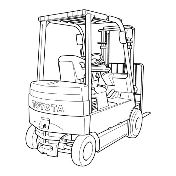
- Page 5 VEHICLE EXTERIOR VIEWS 7FBMF16~35 7FBMF40~50...
- Page 6 MODEL LINE-UP Models Model (80V or 72 V) Capacity (Load Center 500 mm) Previous 1.6 ton 7FBMF16 FBMF16 1 ton Series 1.8 ton 7FBMF18 — 2.0 ton 7FBMF20 FBMF20 2 ton Series 2.5 ton 7FBMF25 FBMF25 3.0 ton 7FBMF30 FBMF30 3 ton Series 3.5 ton 7FBMF35...
- Page 7 STANDARD EQUIPMENTS : STD P:OPT —: Not Available Standard Equipment 1.6-3.5 ton 4.0-5.0 ton Note Electrical AC Power system for travelling & load handling System AC Power controller for steering — 1.6-3.5 ton: DC system Multiple display (All round model) Chassis SAS (System of Active Stability) Wet brake system...
- Page 8 DEVELOPMENT OBJECTIVES Page DEVELOPMENT OBJECTIVES ..........1-2 FEATURES (SELLING POINTS) ..........1-3 AC POWER SYSTEM ..............1-6...
- Page 9 DEVELOPMENT OBJECTIVES TOYOTA 1.6 ~ 3.0 ton FBMF 16 ~ 30 counterbalance type electric 4-wheel forklift trucks have had an estab- lished reputation as high performance forklift trucks since first their model launched in 1989. There have been rising demands for clean electric forklift trucks with relevant to environmental concern; and fur- ther the market wants higher capacity forklift than 3.0 ton beside the existing capacity models.
- Page 10 FEATURES (SELLING POINTS) Table of selling points mfr: manufacturer : Newly adopted, : Improved S: STD, P: OPT, –: Not available 4.0 ~ Relative Selling point Function or Item Objective mfr A 3.5t 5.0t page Improved performance Improvement in operation Power keep function Better performance at a low hours and work cycles without...
- Page 11 1.6 ~ 4.0 ~ Relative Selling point Function or Item Objective mfrA 3.5t 5.0t Page Safety Improved turning stability SAS-active control rear Rear wheel ground grip stabilizer force increased when — 11-6 required Improved material handling SAS-active mast function Controls front tilt angle for stability controller (front tilt angle high lifting, etc.
-
Page 12: General
Outline of Design Major differences from previous models Relative Item New models Applicable Previous models Applicable page model model General Overhead guard 2195mm 1.6 ~ 1.8 ton 2160mm 1.6 ton height 2195mm 2.0 ton 2180mm 2.0 ton 2215mm 2.5 ton 2180mm 2.5 ton 2215mm... - Page 13 AC POWER SYSTEM AC system in industrial trend Industries have already employed AC power system by making use of its features. Three major features are: System design Product level Industry 1970 advantages advantages Simpler and smaller More powerful motor can Machine tool construction of motor be used without...
- Page 14 AC power system as compared with DC power system In the DC power system the controller will chop the battery current in repetition and control the frequency cycles of ON and OFF. The motor performance will change in proportion with the frequency cycles between ON and OFF, thereby the inching at start to the max.
- Page 15 Power keep function (Functions in power mode: P, standard mode: S) Power keep function using the benefit of AC power system further lengthen the operation hours epochally. With conventional electric powered forklift trucks, the vehicle performance decreases gradually as the battery level goes low.
- Page 16 *: Loaded *Loaded: 0-10m *Loaded: 1/10 slope FBMF mfrA FBMF mfrA FBMF mfrA Efficiency operation hours (min) No of cycle (cycle) [d] (Toyota 30m cycle) [e] (Toyota 30m cycle) *Battery 500Ah *Battery 500Ah FBMF mfrA FBMF mfrA Traveling speed (km/h)
- Page 17 1-10 Operator comfort (1) Improvement of the ease of getting on and off By new battery layout, improved the ease of getting on and off (mm) mfrA 7FBMF FBMF Entry clearance (2.5 ton) [a] (2) Improvement of comfort By new battery layout, improved the leg space (mm) mfrA 7FBMF...
- Page 18 1-11 Power select function Using the power select function, the operator can select a desirable power mode. Even though the conventional models also had a power selection switch, it only produced a small difference in the acceleration. New models use an AC motor instead of a DC motor. Since and AC motor is simpler and smaller, it becomes possible to install a motor that produces an output higher than that of a conventional DC motor.
- Page 19 1-12 Reduced maintenance cost The following particular items are inherent to the conventional electric powered models. Supplying distilled water to the battery Material handling motor brush replacement Material handling motor contactor replacement Traveling motor brush replacement Traveling motor contactor replacement The new 7FBMF model eliminates the need for brush and contactor replacement because the new AC motor does not have brushes and the new AC controller does not have contactors.
- Page 20 1-13 Stabilizing features The world-first System of Active Stability (SAS), adopted by the 7FB series models, is available for the new mod- els, too. Using the SAS the new models achieve the stability level equivalent to that achieved by the 7FB series models. The following outlines the SAS.
- Page 21 The model line-up has been widened by the development to 3.5 ~ 5 ton class new model ranges; besides, the 1.8 ton model is added onto the 1 ~ 3 ton classes to meet with varied needs from the markets. : New : Continuation Capacity (kg) 1600 1800 2000 2500 3000 3500 4000 4500 5000 7FBMF TOYOTA FBMF...
-
Page 22: Table Of Contents
CONTROLLER Page MAIN CONTROLLERS ............. 2-2 General ................. 2-2 Controller Configuration Diagram ......2-3 MAIN FEATURES OF CONTROLLER ......... 2-5... -
Page 23: Main Controllers
MAIN CONTROLLERS General AC system The AC motor drive system controller has been provided with: • Microcomputer-assisted travel inverter control (converts DC to three-phase AC) • CAN (Controller Area Network) communication function between main controller and traveling/material han- dling controller. •... -
Page 24: Controller Configuration Diagram
Controller Configuration Diagram 1. Traveling & Load handling controller System configuration diagram Traveling motor temperature sensor Battery Traveling speed sensor Traveling motor Direction switch Traveling driver Traveling accelerator potentiometer AC motor Brake switch Main Parking brake valve controller Material handling potentiometer Material Material Oil control valve... - Page 25 CPU: Central Processing Unit ROM: Read Only Memory (with built-in control program) RAM: Random Access Memory (memory content lost when power turned off) EEPROM:Electrically Erasable Programmable Read Only Memory (memorizes data required for control and er- ror code.) I/O: Input/Output interface CANI/O: Controller Area Network Input/Output interface 2.
-
Page 26: Main Features Of Controller
MAIN FEATURES OF CONTROLLER 1. Regenerative system (accelerator off) When the vehicle travels with the accelerator off, a braking force produced by the motor generates electricity, which is retrieved by the battery. The working of the regenerative system extends the available operation hours and the service life of brake linings. - Page 27 12. Battery level computation The controller monitors decrease in the battery voltage, computes the remaining capacity, and displays it as the current battery level. 13. Diagnostic function The diagnostic function can detect abnormalities in the traveling controller and the material handling control- ler, operation mechanisms such as the accelerator, and sensors.
- Page 28 MULTIPLE DISPLAY Page MULTIPLE DISPLAY INDICATION ........3-2 MULTIPLE DISPLAY FUNCTIONS ........3-3 SERVICE FUNCTIONS ............. 3-9...
- Page 29 MULTIPLE DISPLAY INDICATION General Various essential data with regard to the truck status, warning signs, setting, meters, etc. are visible by switching display. (Indication of will be changed according to the functional operation.) During parking Initial screen after the key switching on Upon error occurrence During traveling No.
- Page 30 MULTIPLE DISPLAY FUNCTIONS Table of Multiple Display Functions : Available —: Not available All-round Easy model Functions model (standard) (optional) Battery capacity indicator Speedometer Travel 2nd speed setting indicator Status display Swing lock indicator Parking brake indicator Power select indicator Power select function Travel power control level setting Level...
- Page 31 Explanation of list items Easy model (standard) and all-round model Difference between easy model (standard) and all-round model (option) As shown in the table, all-round model (option) has additional optional meters, such as No. 20 25 Status display The indications with regard to the existing condition (or Status quo) of the truck before or during the operation Battery capacity indicator Battery capacity indicator shows the remaining battery level in 10 stage mark.
- Page 32 Level setting The level with regard to the manipulation and the performance can be selected and set up in compliance with needs. Power select function Three traveling and material handling modes are available from a selection switch on the multiple display: H (high power) mode, P (power) mode, and S (standard) mode.
- Page 33 Integrating meters (or multiple hour meter) The indication differs between the easy model (standard) and the all-round model (option), as listed in the table on page 3-3. The meter are available to the all-round model. In addition to the key-on-hours, the travelling and the material handling hours, and the travel distance can be shown by total figures.
- Page 34 Display screen list <Initial screen> Initial screen is displayed for a few seconds after key-switch ON. <Initial screen> <Normal function> Press switch ..Travel 2nd speed control ON and OFF <Normal function> The power select Press switch ..Hour meter screen switch is reset in the S →...
- Page 35 <Clock setup selection> Press switch ..Changes the setting from “NO” to “YES” Press switch ..Changes the setting from “YES” to “NO” → Press switch ..Select “YES” Clock set screen → Select “NO” Normal function screen <Clock setup selection>...
- Page 36 SERVICE FUNCTIONS Multiple display has the service function to use when the serviceman maintain and set the specification of the vehicle. Never to destroy important internal data by using the service function wrong, the service functions are protected by the password. Functions Description Used for displaying the operation status of electrical systems...
- Page 37 BATTERY Page SPECIFICATION ................. 4-2 NECESSARY BATTERY WEIGHT ........4-2 RECOMMENDED BATTERIES ..........4-2 BATTERY CONNECTOR RELEASE ........4-2 BATTERY STOPPER ..............4-3 BATTERY INTERCHANGEABILITY ........4-3 RECOMMENDED BATTERY LIST ........4-4 TABLE OF WORKING HOURS ..........4-5...
- Page 38 SPECIFICATION The batteries are not set up as TOYOTA genuine parts. Use a battery compatible to DIN43 536 (See the battery case di- Length mensions listed in the table on page 4-4). In case where high height battery type and battery roll out option are selected, the battery case dimensions are different from the STD type.
- Page 39 Note: Use a battery connector (320A, 50sq) compatible to DIN 127mm 43 589 with Auxiliary electrode (the recommended con- nector is FEM 320A made by REELS. The dimensions of the hook is as illustrated. Don't use any other connec- tor. When a battery is installed locally, always check that the connector can be released by the release lever.
- Page 40 RECOMMENDED BATTERY LIST Installed battery Battery case Necessaey minimum battery weight Dimensions[mm] Dimensions[kg]:With case Battery Capacity Vehicle type Voltage DIN No. Supplier Model type [AH/5hr] Length Width Height 7FBMF16,18 4PzS440L 4PzG400 1026 1220 ↑ ↑ ↑ ↑ VARTA 4PzS440L ↑ ↑...
- Page 41 80, (72) 5 h 35 min. Note: 1. Working Hours 7FBMF16 ~ 35 : TOYOTA 30m operation cycle 7FBMF40 ~ 50 : TOYOTA 50m operation cycle 2. Working Hours of H-Mode 1 ton Series : about 65% down of S-Mode Above 2 ton model : about 73% down of S-Mode 3.
-
Page 42: Power Train
POWER TRAIN Page DRIVE MOTOR ................5-2 DRIVE UNIT ................. 5-7 FRONT AXLE ................5-9 BRAKE ..................5-10 PARKING BRAKE ..............5-13 PARKING BRAKE SYSTEM ..........5-15 BRAKE PEDAL ................. 5-17... -
Page 43: Drive Motor
DRIVE MOTOR General 1. The new models use a newly developed AC induction motor as the drive motor. Being compact, powerful, and maintenance-free, the new motor has ideal characteristics for a motor used in a battery-powered forklift truck. 2. Since the new motor is so compact, it provided enough space under the floor to install the battery. With the battery installed under the floor, the new models incorporate improvements in the ease of getting on and off of the vehicle and operator comfort. - Page 44 Main specifications Nominal Rated output Body size Weight Models Type voltage (V) (kW) Diameter × Length (mm) (kg) φ 7FBMF16,18 72/80 12.0/13.3 Three phase AC 270 × 260 7FBMF20,25,30, φ 72/80 15.4/17.1 Three phase AC 270 × 285 φ 7FBMF40,45,50 72/80 14.9/16.6 Three phase AC...
- Page 45 Structure and principle of AC induction motor AC induction motor has no brushes, commutator and the sliding portion as opposed to the conventional DC mo- tor. Consequently it has the following characteristics: 1. For the same output, the motor dimensions can be reduced by the portion L for the brushes and commutator. 2.
- Page 46 Operational sequence 1. The current flows in a fixed direction in the field winding in the figure. Magnetic field is produced around the field winding in the illustrated direction according to the right-hand rule*, and magnetic poles (N-pole and S- pole) are generated.
- Page 47 Operating principle of motor Before explaining the operating principle of motor, Ampere’s right thread rule and Fleming’s rule will be ex- plained. 1. Right handed screw rule Extend the thumb of the right hand and close the fingers. If you Direction of point the thumb in the direction of current flow as illustrated, the Magnetic...
-
Page 48: Drive Unit
5. As the lubricant, use the gear oil suitable for the wet brake. Note: Use gear oil only TOYOTA specified: SHELL DONAX TD 6. New models like the previous models, helical gear having high transmitting efficiency has been adopted to all the gears. - Page 49 Drive unit sectional view Third axle (front axle center) Second axle (pinion shaft) First axle (motor input shaft) Parking brake...
-
Page 50: Front Axle
FRONT AXLE Difference between previous models and new models The axle housing and the axle brackets are integrated, and bolted to the drive unit housing. The reactive force vs. the drive-force and the brake effects will be received by the axle bracket mount bolts. Type of front axle Semi floating type front axle design has been used for all the models. -
Page 51: Brake
5-10 BRAKE Difference between previous model and new model The wet brake has been adopted in place of the dry brake with the result that reliability and durability have been considerably improved, especially against water and mud. Besides the brake has become free from worn particles out of the brake lining. Dry brake Brake piston Brake disc... - Page 52 5-11 Brake valve The full power type brake valve has been adopted for all the models (1.6 to 5.0 ton capacity). Specification of valve Item 1.6 ~ 5.0 ton Type Full power CHPS Fluid used ISO VG#32 1.6 ~ 3.5 ton From oil pump To oil tank...
- Page 53 TOYOTA Specified oil: SHELL DONAX TD It must be strictly forbidden to use the oil other than those specified by TOYOTA or oil mixed with another since it will give the adverse effect, such as the brake mal-function and the noise occurrence.
-
Page 54: Parking Brake
5-13 PARKING BRAKE The wet disc parking brake has been adopted for all the models (1.6 ~ 5.0 ton). Specification (for all the models) Item 1.6 ton ~ 5.0 ton Parking brake lining dimension 0.45 × 136 ×105 Thickness × Outside Dia. × Inside Dia. Quantity of discs Parking brake oil SHELL DONAX TD... - Page 55 5-14 Parking brake switch • The parking brake system is actuated by the electrical selector switch as illustrated: Turn it to the right: Parking brake on Turn it to the left: Parking brake release Note: • Always stop the truck and turn on the parking brake switch (turn to the right) to engage the parking brake before getting off the vehicle.
-
Page 56: Parking Brake System
5-15 PARKING BRAKE SYSTEM To steering valve and oil control valve Brake change valve solenoid ON/OFF Brake Parking change brake valve Main controller Pump motor for steering (7FBMF15~35) Oil pump Pump motor (7FBMF40, 45&50) Electrical signal Hydraulic line Function 1. The parking brake will be released when it receives oil pressure from the brake change valve. When it does not take oil pressure, it becomes the condition that a parking brake piston is pressed by the cone spring, and the parking brake is effective. - Page 57 5-16 5. To try to travel the vehicle makes the parking brake released. When all the following conditions are satisfied, the parking brake is released by turning on the solenoid valve. • Turning on the key switch • Turning on the seat switch (The seated condition) •...
-
Page 58: Brake Pedal
5-17 BRAKE PEDAL • 1.6 ~ 3.5 ton New models use the pendent type brake pedal in place of the step down type brake pedal on the previous models. • 4.0 ~ 5.0 ton: The pendent type brake pedal and the double link mechanism have been adopted. Regenerative sensor The limit switch has been adopted for reliability as that of the previous model, and sensing ability has been im- proved. -
Page 59: Steering & Rear Axle
STEERING & REAR AXLE Page STEERING ...............6-2 REAR AXLE (1.6 ~ 3.5 ton model) .........6-5 REAR AXLE (4.0 ~ 5.0 ton model) .........6-7... - Page 60 STEERING 1.6 ~ 3.5 ton Power steering system New models like the previous models have adopted Electronically controlled fully-Hydraulic Power Steering (EHPS) as the standard equipment. Brake valve for parking release Solenoid valve for knob PS pump PS valve Steering sensor Oil tank Rear axle beam PS cylinder...
- Page 61 Principle of EHPS (Electronically controlled full-Hydraulic Power Steering) 1. The steering sensor will defect the steering wheel revolution speed without mechanical contact while the op- erator rotating the steering wheel. 2. In the meantime, the detected speed is turned into electronic pulse signals and being sent to the controller. 3.
-
Page 62: Tires
4.0 ~ 5.0 ton Power steering system Fully hydraulic power steering has been adopted as the standard equipment. Solenoid valve Brake valve PS valve Brake valve for parking release Oil tank Pump Rear axle beam PS cylinder Power Steering valve (PS valve) 1. -
Page 63: Fbmf
REAR AXLE (1.6 ~ 3.5 ton model) The structure of the rear axle for the new models is similar to that of the previous FBMF series. As the illustration shows, the lock cylinder rod mount clevis has been added on the portion (B) for the active rear stabilizing control. The rear axle cylinder mount pins (A) are eccentric in shape so that the wheel angle can be adjusted by rotating the eccentric pin as illustrated on the next page. - Page 64 ° ° Rotation of cylinder pin (min.) ~ 360 (max.) ° Toe-in side: Approx. 1.5 Tire angle adjustment range ° Toe-out side: Approx. 1 Toe-out side Toe-out side approx approx 1° 1° Toe-in side Toe-in side approx approx 1.5° 1.5° Adjustment of cylinder pin angle Lock plate...
- Page 65 REAR AXLE (4.0 ~ 5.0 ton model) The rear axle assembly parts are similar to those of 7FB35 series. 1. The rear axle can be lubricated with grease at 12 points (A1 ~ A12) shown in the illustration, while steerig the rear axle to the left and right.
- Page 66 ° ° Rotation of cylinder pin (min.) ~ 360 (max.) ° Toe-in side: Approx. 1.5 Tire angle adjustment range ° Toe-out side: Approx. 1 Toe-out side Toe-out side approx approx 1° Toe-in side Toe-in side 1° approx approx 1.5° 1.5° Adjustment of cylinder pin angle Lock plate...
- Page 67 TIRES Page SPECIFICATIONS ..............7-2 7FBMF16 ~ 35 Tire Specifications ......7-2 7FBMF40, 7FBMF45, and 7FBMF50 Tire Specification .............. 7-3 SPECIFICATION TABLE ............7-5 7FBMF16·18·20·25·30·35 ..........7-5 7FBMF40·45·50 ..............7-6...
-
Page 68: Specifications
SPECIFICATIONS 7FBMF16 ~ 35 Tire Specifications General • New models like previous models have adopted the pneumatic shaped cushion tire. • A pneumatic tire is available as the option for 7FBMF16, 7FBMF18, 7FBMF20, and 7FBMF25 models. • The wide tread specifications are available as the option for 7FBMF16 ~ 35 with the standard size. •... -
Page 69: 7Fbmf40, 7Fbmf45, And 7Fbmf50 Tire Specification
Table 4 7FBMF30 and 7FBMF35 Standard Tire Over size Tire Standard Tread Wide Tread Standard Tread Wide Tread × × Tire Size 10-12 10-12 Tread (Front) 1070 Overall Width 1220 1320 Rear tire Table 5 7FBMF16~35 rear tire 7FBMF16·18·20 7FBMF25 7FBMF30·35 ×... - Page 70 Note: • Front tire wheels are not interchangeable between the new models and the previous models. • The interchangeability of the rear wheels between the new models and the previous models is as shown in Table 8. • The truck with the non-marking white tires should be equipped with the earth band for grounding where the working floor has high friction factor such as resin coat, because the condition has high po- tential to generate static electricity.
-
Page 71: Specification Table
SPECIFICATION TABLE 7FBMF16·18·20·25·30·35... - Page 72 7FBMF40·45·50...
- Page 73 OPERATOR’S COMPARTMENT Page OPERATOR’S COMPARTMENT ........... 8-2 DRIVING POSITION ..............8-3 SEAT ....................8-4 ACCELERATOR PEDAL ............8-6 DIRECTION SWITCH ..............8-7 INSTRUMENT PANEL .............. 8-8...
-
Page 74: Operator's Compartment
OPERATOR’S COMPARTMENT Pattern of shift Layout of pedal NAME NAME Parking switch Control lever (Lift) Horn switch Control lever (Tilt) Direction lever Control lever (Attachment) Turn signal switch (OPT) Control lever (Attachment) Ignition key switch Brake pedal Light switch Accelerator pedal Steering wheel Tilt steering lock lever Seat... -
Page 75: Driving Position
DRIVING POSITION The new model mounted with the battery assembly underfloor room creates the ample foot space, contributing to the operation comfort. (The same as that of 7FB25 having established evaluation in the market.) The enlarged distance between the operator’s seat and the accelerator pedal (with FBMF series in comparison) will relieve the operator of ankle fatiguing by daily work. -
Page 76: Seat
SEAT The same seat as 7FGF25 series has been adopted to 7FMF16 to 50. (The same seats have had an established reputation by the name of Grammer seat). The new seat is provided with the seat switch function. Features: 1. ORS (Operator Restrain System) If the truck should tip over, ORS will protect the operator by restraining means. - Page 77 Seat stand opening & closing Procedure: Open and close the seat stand by the following procedure. <7FBMF16~35> 1. Move the mini lever box to the rearmost position. 2. Slide the seat to the foremost position. 3. Pull the lock release lever, and tilt the steering post forward. 4.
-
Page 78: Accelerator Pedal
ACCELERATOR PEDAL The accelerator pedal is installed on the front toe board. The feeling of initial operation became smoother thanks to the resin mold pedal. With the enlarged (A) pedal stroke angle combined with the change of the seated position (See Page 8-3), the ankle will be relieved of fatigue. -
Page 79: Direction Switch
DIRECTION SWITCH • A finger touch type direction switch has been adopted to reduce the force needed for operation and to make it easier to operate with the fingertips (same as in previous model). • An exclusive resin knob, similar to that of turn signal switch, is used at the lever tip to improve the design around the steering wheel (same as in current model). -
Page 80: Instrument Panel
INSTRUMENT PANEL Instrument panel • Resin fabrication realized new design. • The instrument panel consists of two pieces on 7FBM16 to 35 and three pieces, on 7FBMF40 to 50. The quality of the material is excellent in intensity and is made from eco-friendly polypropylene. •... -
Page 81: Body & Accesories
BODY & ACCESORIES Page NOTICES-HOIST AND JACK POSITION ......9-2 BODY & FRAME ................. 9-3 ACCESSORIES ................9-6 Lights ..................9-6... -
Page 82: Notices-Hoist And Jack Position
NOTICES-HOIST AND JACK POSITION 1. Hoisting by holding the mast and the rear wheels When hoisting the vehicle, hold the front by the outer mast top tie beam, and the rear by the rear tire wheels. Never use overhead guard or counter weight to hoist the vehi- cle. -
Page 83: Body & Frame
BODY & FRAME Fender As for the wide tread/specs., (2.0 to 3.5 ton) and the dual tire specs (4.0 to 5.0 ton), the fenders are bolted on the body frame to cover the front wheels. Fender Counterbalance weight In the previous models, the controller is enclosed in the counterbalance weight. In the new models, the controller is installed into the partition covered by the seat stand to protect it from getting wet. - Page 84 Step 7FBMF 16 ~ 35 • Aiming at unique, and unchangeable cleanliness desirous for the electric forklift trucks, the step on the LH side has been made from resin compound, so that the step has become corrosion free and water clean feature. •...
- Page 85 Toe Board The toe board is separated into two parts, front and rear. Battery maintenance can be easily performed. The rear toe board consists of two plates hinged at the middle between them so that the battery change or the battery maintenance will be facilitated. The front toe board can be lifted without using the tool since it is not bolted to the place.
-
Page 86: Accessories
ACCESSORIES Lights (1) List of lights and OPT settings OPT: Option Front combination light Head light Rotary beacon Rear working light Rear combination light... - Page 87 Headlights As with previous model, headlight is large diameter square type with guard. Front combination lights As 7FB25 model, the front combination light is integrated. Front combination lights with If outside mast piping OPT and front Mast combination lights in 7FBMF40 ~ 50 FSV or FV (7FBMF40 ~ 50, FSV or FV, A450, the lights are installed with mast.
- Page 88 (2) Light switch The position of the light switch has been changed to the left of steering wheel, and it improves operation. The switch is 3-step switching, and it is possible to switch the lights with one switch. 1st step : Clearance lights, Tail lights 2nd step : Head lights, Clearance lights, Tail lights 3rd step : Clearance lights, Tail lights, Rear working light LIGHT SWITCH...
-
Page 89: Material Handling & Hydraulics System
10-1 MATERIAL HANDLING & HYDRAULICS SYSTEM Page V MAST ..................10-2 FV MAST ..................10-4 FSV MAST .................. 10-5 FORK, FORKBAR, AND LOAD BACKREST ....10-6 MAST WEIGHT ................. 10-8 MAST INTERCHANGEABILITY ........... 10-9 HYDRAULIC CIRCUIT ............10-10 LOAD HANDLING LEVER (MINI-LEVER) ....... - Page 90 10-2 V MAST The V mast is standard equipment. The basic structure of the V mast of 7FBMF16 to 30 is the same as that of the previous model. The basic mast structure of 7FBMF35 is the same as 7FGJF35. The basic mast structures of 7FBMF40, 45 and 7FBMF50 are the same as 7FD35 and 7FD45 respectively.
- Page 91 10-3 5) Lift cylinder piping The basic structure of the lift cylinder piping of 7FBMF16 to 30 is the same as that of the previous model. The safety down valve is an inline type similar to that of the previous model, but the additional fitting for the pressure sensor is connected.
-
Page 92: Fv Mast
10-4 FV MAST Full-free mast (FV mast) The FV mast is available as an option except for 7FBMF35 and 7FBMF50. The basic structure of the FV mast of 7FBMF16 to 30 is the same as that of the previous model. The mast of 7FBMF40 and 45 is the same as 7FD35. -
Page 93: Fsv Mast
10-5 FSV MAST Full-free three-stage mast (FSV mast) The FSV mast is available as an option. The basic structure of the FSV mast of 7FBMF16 to 30 is the same as that of the previous model. The basic mast structure of 7FBMF35 is the same as 7FGJF35. The basic mast structures of 7FBMF40, 45 and 7FBMF50 are the same as 7FD35 and 7FD45 respectively. -
Page 94: Fork, Forkbar, And Load Backrest
10-6 FORK, FORKBAR, AND LOAD BACKREST Fork The fork of 7FBMF16 to 30 is the same as that of the previous model. The fork of 7FBMF35 is the same as that of 7FGJF35. The fork of 7FBMF40 to 50 is a newly adopted one. Refer to the table of “6.2. Fork” about its size. The standard fork color is black. - Page 95 10-7 7FBMF40 ~ 50 (V,FV,FSV) Length of forkbar (mm) Outside width of load backrest [+60 mm] Model 1170 1320 1470 1630 Height of 7FBMF40, 45 load 1220 backrest 7FBMF50 (mm)
-
Page 96: Mast Weight
10-8 MAST WEIGHT Maximum 7FBMF16, 18 7FBMF20, 25 7FBMF30 7FBMF35 7FBMF40, 45 7FBMF50 Mast fork height Type 3000 1060 3300 1100 3500 1110 3700 1170 4000 1050 1270 4500 1100 1350 5000 1150 1430 3000 3300 3500 3700 1000 4000 1100 3700 1070... -
Page 97: Mast Interchangeability
10-9 MAST INTERCHANGEABILITY 1: Interchangeability in the new model Mast Model group 7FBMF16, 18 7FBMF20, 25 7FBMF30 7FBMF35 — 7FBMF40, 45 7FBMF50 — : Interchangeable with the other masts in each model groups. : Interchangeable, but the tilt cylinder has to be exchanged at the same time. 2: Interchangeability with the previous model There is no interchangeability of the mast between the previous model and the new model. -
Page 98: Hydraulic Circuit
10-10 HYDRAULIC CIRCUIT A general hydraulic circuit is shown below. 1.6 ton ~ 3.5 ton Lift cylinder Oil control valve Return filter Tilt cylinder tank Brake valve Steering & Brake change return valve return Steering valve Suction filter Change pump valve Solenoid valve... - Page 99 10-11 4.0 ton ~ 5.0 ton Lift cylinder Oil control valve Return filter Tilt cylinder tank Brake return Change Steering Steering return valve return valve Suction filter pump Brake valve Change Solenoid valve valve Pump motor Power steering cylinder Parking brake Service brake Both suction and return filters are provided as standard equipment to protect the hydraulic equipment.
-
Page 100: Load Handling Lever (Mini-Lever)
10-12 LOAD HANDLING LEVER (MINI-LEVER) 1) The structure of mini-lever Mini lever is available as standard to meet the demand of European market. The operation stroke has been made smaller and operating force has been decreased by changing the position of the lever from over cowl to right front of the seat. - Page 101 10-13 Lift lever Automatic fork leveling switch Guard Tilt lever Arm pad Adjustable Knob for fixing lever box Attachment lever...
- Page 102 10-14 2) The structure of armrest Armrest is installed to lessen the operator’s fatigue of right arm when driving the vehicle and operating hydraulic lever. The material of the arm pad is polyurethane. It is soft and fits the arm and the palm. Armrest is fixed on battery hood, and it does not move with seat slide.
- Page 103 10-15 Large operator (stature 1840 mm) Medium operator (stature 1755 mm) Small operator (stature 1670 mm) Every operator can choose the most suitable position to operate the lever. Adjustable Adjustable Knob for fixing the armrest Lever for locking and releasing mini-lever box 7FBMF 40, 45, 50 7FBMF 16, 18, 20, 25, 30, 35...
-
Page 104: Oil Control Valve
10-16 OIL CONTROL VALVE General The electric proportional oil control valve for mast control has been adopted. The following point has been adopted. • The tilt circuit is equipped with a logic valve and the electric proportional valve for control of the mast tilt operation. - Page 105 10-17 Specifications Unit: MPa (kgf/cm )[psi] 7FBMF20 ~ 35 7FBMF16 ~ 18 7FFBMF40 ~ 50 16.2 18.1 Relief pressure (165) (185) (2350) (2630) Material handling valve 1.6 ~ 3.5 ton models • Pressure compensation mechanism Pressure oil flowing from port P flows from chamber (a) through orifice A to chamber (b), then flows through orifice B to chamber (c).
- Page 106 10-18 • Backpressure leak reduction mechanism Port C1 of the lift cylinder is connected to the bottom of the lift cylinder, and port C3 of the tilt cylinder is con- nected to the rod side of the tilt cylinder. When load pressure from port C1 and port C3 is applied, leakage to chamber (i) and chamber (j) is controlled by H and I on the seat.
- Page 107 10-19 • Hydraulic pressure mechanism for solenoid proportional valve The pressure oil that has had its pressure reduced by the pressure reducing valve flows to chamber (f), then flows through passage 4 and the filter to become the pilot pressure to each solenoid. The pressure of the oil is determined by the set load on spring 4.
- Page 108 10-20 • Load-sensing mechanism The pressure compensation valve, unload valve and sensing circuit are part of pressure compensation oper- ation. When the spool strokes, chamber 7 connects to each cylinder port. Sensing pressure is the cylinder pressure, which gives feedback to the pressure compensation valve. When sensing pressure + pressure of spring (2) = pressure of chamber (d) and chamber (c), the pressure com- pensation valve moves to the equilibrium position.
- Page 109 10-21 • Lift UP operation When the lift lever is pushed to the UP side, solenoid b1 is energized and the solenoid proportional valve moves to the right. Then the pressure oil controlled by the pressure reducing valve flows to chamber (k) on the left side, and the lift spool moves to the right side.
- Page 110 10-22 • Lift DOWN operation When the lift lever is pushed to the DOWN side, solenoid a1 is energized and the solenoid proportional valve moves to the left. Then the pressure oil controlled by the pressure reducing valve flows to chamber (m) on the right side, and the lift spool moves to the left side.
- Page 111 10-23 • FORWARD tilt operation When the tilt lever is pushed to the FORWARD side, solenoid a2 is energized and the solenoid proportional valve moves to the left. Then the pressure oil controlled by the pressure reducing valve flows to chamber (o) on the right side, and the tilt spool moves to the left side.
- Page 112 10-24 • REAR tilt operation When the tilt lever is pushed to the REAR side, solenoid b2 is energized and the solenoid proportional valve moves to the right. Then the pressure oil controlled by the pressure reducing valve flows to chamber (u) on the left side, and the tilt spool moves to the right side.
- Page 113 10-25 • Attachment When you operate the attachment lever, solenoid b3 is energized and the solenoid proportional valve moves to the left. Then the pressure oil controlled by the pressure reduction valve flows to chamber (p) on the left side and the spool moves to the right side.
- Page 114 10-26 4.0 ~ 5.0 ton models • Pressure compensation system • When pressure compensation mechanism is ON When solenoid c1 is energized and the non-leak valve is closed, the pressure compensation mechanism operates the same way as for the 1.6 ~ 3.5 ton models. •...
-
Page 115: Pump Motor
10-27 PUMP MOTOR General 1. The pump motor like the drive motor uses AC induction motor, Terminal Rotor ideal for the electric forklift design, featuring higher performance Field winding even with the compact sizing combined with the maintenance free advantage. 2. -
Page 116: Steering Motor
10-28 STEERING MOTOR The steering motor for use in 7FBMF series has been unchanged from that of FBM series, featuring the high output and reliance on quality. Previous model New model Voltage Size Rated output Voltage Size Rated output Type Type (mm) (kW) -
Page 117: Oil Pump
10-29 OIL PUMP An externally mounted type gear pump is used. 1.6 to 3.5 ton series use 1 pump as in the previous model. 4.0 to 5.0 ton series use dual pump. No.1 pump is used for load handling. No.2 pump is used for brake and pow- er-steering. -
Page 118: Lifting Speed
LIFTING SPEED... -
Page 119: Tilt Cylinder
10-31 TILT CYLINDER The tilt cylinder for 7FBMF16 to 30 is changed from the previous model. It is the same cylinder as that of 7FGF25 series. • The size of the tilt cylinder is reduced so that it can be hidden from the foot space. •... -
Page 120: Oil Tank
10-32 OIL TANK Oil tank 1.6 ~ 3.5 ton (same as in previous model) Tank is constructed of welded iron plates, independent of the frame structure, bolted on the rear frame. Filling and checking of oil can be carried out easily by opening the battery hood. Return filter is under the front toe-board. - Page 121 10-33 Oil tank 4.0~5.0 ton Tank is constructed of welded iron plates, independent of the frame structure, bolted on the side of left frame. Filling and checking of oil can be carried out easily by opening the battery hood. Level gage & cap Hose Breather Oil tank cover...
-
Page 122: Other Hydraulic Parts
10-34 OTHER HYDRAULIC PARTS Oil tank cover (same as in previous model) The oil tank cover is constructed with various pipes welded to it. A special packing that completely prevents ooze or leakage of oil is used for positive sealing. Oil tank cover Packing Oil tank... -
Page 123: A4 Piping
10-35 A4 PIPING 1: List of available A4 type 7FBMF16 ~ 30 7FBMF35 Oil control Numbers of Piping Piping type Mast Mast valve hoses position A405 4-way None A410 3-way Inside A430 4-way Inside A450 4-way Inside 7FBMF40, 45 7FBMF50 Oil control Numbers of Piping... - Page 124 10-36 7FBMF35 V The piping is the hose-integrated type and the same as that of 7FGJF35. 7FBMF40 ~ 50 V The piping is the hose-integrated type and the same as that of 7FD35 series. 7FBMF16 ~ 30 FSV, FV The piping is the same as that of the previous model. 7FBMF35 FSV The piping is the same as that of 7FGJF35.
- Page 125 10-37 5: Termination type 7FBMF16 ~ 35 The position of the A4 piping termination on the lift bracket is the same as that of the 7FGF25 series. 7FBMF40 ~ 50 The position of the A4 piping termination on the lift bracket is the same as that of the 7FD35 series. The screw size of the termination fitting is 9/16-18 UNF.
- Page 126 11-1 Page OUTLINE OF SAS ..............11-2 ACTIVE CONTROL REAR STABILIZER ......11-6 ACTIVE MAST FUNCTION CONTROLLER ....11-10 ACTIVE STEERING SYNCHRONIZER FHPS ....11-14...
-
Page 127: Outline Of Sas
11-2 OUTLINE OF SAS General 1. Excellent stability and high-technology realized in our forklift is sure to gain customer’s satisfaction. 2. On basis of the engineering theme “safe material handling”. SAS (System of Active Stability) has been developed. Purpose of SAS ➔... - Page 128 11-3 System configuration Limit switches and sensors are installed at various positions of the vehicle. These sensors detect the condition of various components of the vehicle and send specific signals to the controller. These signals are processed by the controller, and then specific commands are sent to each actuator to perform desired motion. Input Output Control...
- Page 129 11-4 Names and functions of each component 1. Names of each component (4.0 ~ 5.0 ton) (1.6 ~ 3.5 ton) Lift height switch Swing lock cylinder Tilt angle sensor Electric proportional oil control valve Tilt lever potentiometer LCD display Automatic fork leveling switch •...
- Page 130 11-5 2. Functions of each component Input to controller Name Function The limit switch installed on the outer mast detects the height of the inner mast. Lift height switch Then it is determined whether the lift is on the lower stage or upper stage with respect to the specified height.
-
Page 131: Active Control Rear Stabilizer
11-6 ACTIVE CONTROL REAR STABILIZER General Forklift trucks are used to carry a heavy load, lift it high, and make a small turn with the load. “Active Control Rear Stabilizer” is developed to ensure stability in operating these vehicles. In this system the vehicle information from each sensors is sent to the active control rear stabilizer. - Page 132 11-7 It gives the center of gravity more allowances before it gets out of the safe area formed by the four points. In other words, the distance the center of gravity can travel in the square (A2) is larger than that in the triangle (A1), thus enhancing lateral stability as shown below.
- Page 133 11-8 Frame Swing lock effected circuit Swing lock cylinder Swing lock released circuit Cap end chamber Solenoid valve Head end chamber Rear tire Center pin Rear axle beam Structure and operation The rear axle suspension method is the same as the previous model. It is designed to swing with respect to the center pin.
- Page 134 11-9 Conditions of swing lock There are two controller commanding routes for the swing lock. Whichever route it takes, the swing lock will en- gage. Swing lock command caused by lateral acceleration Swing lock while traveling Swing lock command caused by yaw rate signal Lateral acceleration Lateral acceleration...
-
Page 135: Active Mast Function Controller
11-10 ACTIVE MAST FUNCTION CONTROLLER General The active mast function controller has the following features. 1. Active mast front tilt angle control This function automatically moderates the front tilt angle of the mast depending on the load and lift height. It can prevent the load from falling or the vehicle from turning over in such a case as the operator inadvertently tilted the mast excessively forward. - Page 136 11-11 Description of operation Active mast front tilt control 1. The forward tilt angle varies depending on the lift height and load as follows: Light load (no load) Intermediate load Heavy load No restriction for Angle restricted between Forward tilt angle High lift height front tilt angle 1°...
- Page 137 11-12 Active mast rear tilt speed control 1. In the upper lift height stage, the rear tilt speed is restricted to be slow regardless of the load. The speed restraint will be continued if the lift enters the lower stage from the upper stage during rear tilting process. 2.
- Page 138 11-13 Availability of the mast control in reference to attachment extra weight In case that the heavy attachment is used, if the additional weight (due to attachment) value exceed the values shown in the table, on such a truck model, the tilt forward angle is restricted to approx. 1°, and it is impossible to use the automatic fork leveling control at high lift height.
-
Page 139: Active Steering Synchronizer Fhps
11-14 ACTIVE STEERING SYNCHRONIZER FHPS General 1. A sensor installed under the steering wheel detects the wheel angle and the tire angle sensor installed above the rear axle king pin detects the rear tire angle. If any mismatch is found between the two angle date, the solenoid valve opens to compensate the difference. - Page 140 12-1 MAIN OPTIONS & ATTACHMENTS Page FISHERMAN SPECIAL ............12-2 BATTERY ROLL-OUT ............. 12-3 HIGH HEIGHT BATTERY TYPE ........... 12-6 FULLY OIL CHARGED LIFT CYLINDER ......12-9 DUAL TIRES ................12-9 MASTLESS ................12-10 CAUTIONS IN ORDERING ..........12-11 ATTACHMENT LIST ..............
- Page 141 12-2 FISHERMAN SPECIAL The fisherman special whose anti-rust effect is higher than STD model is newly set up as an option. Please rec- ommend this to the customers who use 7FBMF series in severe working condition, e.g. : • in the marine products industry, •...
-
Page 142: Battery Roll-Out
12-3 BATTERY ROLL-OUT Model Available for 7FBMF16 to 50. Structure In order to replace the OPT size battery from RH side, the battery roll-out specifications use different parts such as the frame, the seat stand, the side hood and the rear toe board from standard. (They are not available for STD size battery.) Main structure is as illustrated: Frame (The head guard has no opening slit for... - Page 143 12-4 Battery removal procedure Remove the battery according to the following procedure. (7FBMF16 ~ 35) 1. Open the seat stand. 2. Open the battery stopper. 3. Slide out the battery to the right. To install the battery, reverse the above procedure. Note: Use the same procedure as on high height spec.
- Page 144 12-5 ( 7FBMF40 ~ 50 ) 1. Open the seat stand. 2. Release the battery stopper lock. 3. Open the battery stopper. 4. Slide out the battery to the right. To install the battery, reverse the above procedure. Note: Use the same procedure as on high height spec. to open and close the seat stand. Attention: 1.
-
Page 145: High Height Battery Type
12-6 HIGH HEIGHT BATTERY TYPE Model Available for 7FBMF16 to 50. Structure (7FBMF16 ~ 35) In order to mount the OPT battery (*) , the high height battery type uses different seat stand and rear toe board from standard truck. →... - Page 146 12-7 (7FBMF40 ~ 50) In order to mount the OPT battery (*), the high height battery type uses different seat stand and rear toe board from standard truck. Remarks: And, battery stopper is added. (*): DIN 43 536 6PzS840L (6PzS720) Enclosed in the bracket ( ) shows the previous code.
- Page 147 12-8 Seat stand locking device A locking device and a catch are provided at the front edge of the seat stand, to securely hold the seat stand in place while the truck is operated. (7FBMF16 ~ 35) The locking device automatically locks to the frame side when the seat stand is closed, thus making it impossible to forget to lock the hood.
-
Page 148: Fully Oil Charged Lift Cylinder
12-9 FULLY OIL CHARGED LIFT CYLINDER Fully oil charged lift cylinder is available for 7FBMF16 to 35 as an option. See the table below regarding the availability of this option. Model Mast Availability 7FBMF16 ~ 35 — (*) 7FBMF40 ~ 50 —... -
Page 149: Mastless
Note: • Install the genuine TOYOTA mast of 7FBMF series for SAS on the truck according to the repair manual. • It is necessary to reset the SAS (System of Active Stability) after installing the mast. -
Page 150: Cautions In Ordering
12-11 CAUTIONS IN ORDERING Fisherman special 1. Electrical parts on the STD models such as the motors are vulnerable to salt water or chemicals when the customer deals with the loads like the fresh fish, pickles, leather, etc. on the following conditions: •... - Page 151 12-12 Cautions in handling 1. Do not blindly rely on the active control rear stabilizer. (Refer to the page 11-7.) 2. Do not blindly rely on the active mast front tilt angle control. (Refer to the page 11-11, 11-12.) 3. Quit to turn off the PKB key switch unnecessarily, because the vehicle stops sharply in the case that turned off the PKB switch during traveling.
-
Page 152: Attachment List
12-13 ATTACHMENT LIST Side shifter Attachment E811 E811A E811B E911 E911A E911B Integrated Integrated Hooked Hooked Truck model Integrated Hooked on +A430 +A450 on+A430 on+A450 7FBMF16 7FBMF18 7FBMF20 7FBMF25 7FBMF30 7FBMF35 7FBMF40 — — — 7FBMF45 — — — 7FBMF50 —... - Page 153 12-14 Specification 7FBMF16,18 Fork bar width Assembly weight 50.3 Effective thickness Max. sideshift : STD in E9 Series : OPT 7FBMF20,25 Fork bar width 1020 1170 1470 Assembly weight 53.5 59.0 88.3 ← ← Effective thickness ← ← Max. sideshift Series 7FBMF30 Fork bar width...
- Page 154 12-15 Others 1. Fork & backrest Fork & backrest are the same as those of the standard truck models. So series options of the standard truck models are available. 2. A4 piping The E9 attachments including the A4 piping are as shown: E9-code A4-type E911...
- Page 155 12-16 Specification 7FBMF16,18 Fork bar width Max. sideshift : STD in E8 Series : OPT (Option) 7FBMF20,25 Fork bar width 1020 1170 1470 ← ← Max. sideshift Series 7FBMF30 Fork bar width 1070 1170 1470 ← ← Max. sideshift Series 7FBMF35 Fork bar width 1070...
- Page 156 13-1 WIRING DIAGRAM Page WIRING DIAGRAM (1.6 ~ 3.5 TON MODEL) ....13-2 WIRING DIAGRAM (4.0 ~ 5.0 TON MODEL) ....13-3...
- Page 157 18-53 7FBMF 16-35 Toyota - Kabelfärger på elschemat B = Svart BR = Brun DG = Mörkgrå G = Grön L = Ljusblå LG = Ljusgrön O = Orange P = Rosa PU = Lila R = Röd W = Vit...
- Page 158 18-54 7FBMF 40-50 Toyota - Kabelfärger på elschemat B = Svart BR = Brun DG = Mörkgrå G = Grön L = Ljusblå LG = Ljusgrön O = Orange P = Rosa PU = Lila R = Röd W = Vit...
Need help?
Do you have a question about the 7FBMF 18 and is the answer not in the manual?
Questions and answers
Не едет погрузчик после того как наберет рабочею температуру
The Toyota forklift with part number 7FBMF 18 may stop moving after reaching operating temperature because the temperature sensors in the motor and controller detect overheating. To prevent damage, the controller restricts current to the motors, reducing or stopping performance. This is a normal function to avoid overheating. When this happens, the monitoring display shows an overheat warning. Operation should be paused until the warning disappears.
This answer is automatically generated