
Related Manuals for GBD FLOOR 830


Summary of Contents for GBD FLOOR 830
- Page 1 FLOOR FLOOR 830 - (81300) Operatore oleodinamico interrato FLOOR 824 - (81324) ISTRUZIONI PER L’INSTALLAZIONE Underground hydraulic operator INSTRUCTIONS FOR INSTALLATION...
- Page 2 FLOOR • Questo prodotto è stato collaudato in GI.BI.DI. verificando la perfetta corrispondenza delle caratteristiche alle direttive vigenti. • La GI.BI.DI. S.r.l. si riserva la facoltà di modificare i dati tecnici senza avviso, in funzione dell'evoluzione del prodotto. LEGGERE ATTENTAMENTE QUESTO MANUALE PRIMA DI PROCEDERE ALL’INSTALLAZIONE.
-
Page 3: Avvertenze Per L'installazione
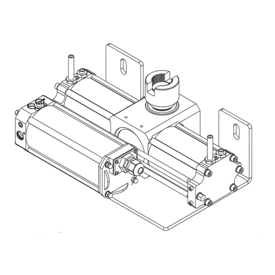
L'automazione è composta da un operatore interrato, che trasmette il movimento all'anta, e da una centralina oleodinamica di distribuzione integrata nell'operatore. Gli operatori FLOOR 830-824 sono intercambiabili con le versioni FLOOR 810-812, rifarsi al capitolo 18 “Installazione operatore FLOOR 830-824 in una cassetta FLOOR preesistente”. -
Page 4: Avvertenze Per L'utente
FLOOR AVVERTENZE PER L’UTENTE In caso di guasto o anomalie di funzionamento staccare l'alimentazione a monte dell'apparecchiatura e chiamare l'assistenza tecnica. Verificare periodicamente il funzionamento dei dispositivi di sicurezza. Le eventuali riparazioni devono essere eseguite da personale specializzato usando materiali originali e certificati. Il prodotto non deve essere usato da bambini o persone con ridotte capacità... -
Page 5: Dati Tecnici
È importante che sulla linea di alimentazione venga installato, a monte dell'apparecchiatura, un interruttore magnetotermico-differenziale omnipolare con apertura minima dei contatti pari a 3 mm. 2 - DATI TECNICI OPERATORE FLOOR 824 FLOOR 830 Frequenza di utilizzo (%Fu) a 20°C 80% 2a 40% 2b Motore elettrico... - Page 6 FLOOR Curva di massimo utilizzo Dai grafici 2a e 2b è possibile ricavare il tempo di funzionamento in base alla frequenza di utilizzo desiderata. Diagramma applicativo Dal grafico 2c è possibile determinare la massima lunghezza dell'anta in base al peso della stessa. 3 - DIMENSIONI Riferimenti ad immagine 4 - NOMENCLATURA CASSETTA DI FONDAZIONE...
-
Page 7: Avvertenze Preliminari
FLOOR 6 - AVVERTENZE PRELIMINARI • Verificare che la struttura del cancello sia adeguata per accogliere l'operatore. • Verificare che le parti fisse e mobili del cancello siano strutturalmente integre ed adeguate o se richiedono opere di rinforzo. • Verificare che le parti soggette ad attriti, in particolare la cerniera superiore, non richiedano opere di messa a punto. - Page 8 FLOOR 8 - MURATURA CASSETTA DI FONDAZIONE 1 - Eseguire uno scavo nel terreno sottostante al pilastro 8a , creare una base di ciottolo di ghiaia per evitare ristagni di acqua Á 8a . 2 - La cerniera inferiore preesistente non serve e va rimossa À 8a .
- Page 9 FLOOR • Saldare il perno autoportante sul profilo ad U facendo in modo che l'estremità fresata sia perpendicolare al profilo ad U 9e . • Lubrificare con grasso il pignone autoportante. • Inserire nella cassetta il perno autoportante col profilo ad U saldato. •...
-
Page 10: Regolazione Della Velocità
FLOOR 12 - REGOLAZIONE DELLA COPPIA ESPRESSA Per aumentare la coppia espressa, ruotare con l'ausilio di un cacciavite, in senso orario le valvole Æ e Ç per diminuire la coppia espressa ruotare le valvole in senso antiorario. In dettaglio sull'operatore installato sull'anta SINISTRA: •... - Page 11 FLOOR In dettaglio sull'operatore installato sull'anta SINISTRA: • La valvola È 5 controlla la reversibilità in APERTURA. • La valvola É 5 controlla la reversibilità in CHIUSURA. In dettaglio sull'operatore installato sull'anta DESTRA: • La valvola È 5 controlla la reversibilità in CHIUSURA. •...
-
Page 12: Manutenzione
Per maggiori dettagli e informazioni sulle normative di riferimento potete collegarvi al sito internet: www.gibidi.com 18 - INSTALLAZIONE OPERATORE FLOOR 830-824 IN UNA CASSETTA FLOOR PREESISTENTE In caso si debba procedere alla installazione dell'operatore all'interno di una cassetta preesistente è necessario verificare che la cassetta abbia il montante di supporto dell'anta sagomato come in À... - Page 13 OPERATORE OLEODINAMICO FLOOR 824-830 sono conformi alle seguenti Direttive CEE: • Direttiva EMC 2004/108/CE e successive modifiche; • Direttiva LVD 2006/95/CE e successive modifiche (FLOOR 830) e che sono state applicate le seguenti norme armonizzate: • EN60335-1; EN61000-6-1; EN61000-6-3 Data 10/03/2011...
- Page 14 FLOOR • This product has been tested in Gi.Bi.Di. verifying the perfect correspondence of the characteristics to the current directive. • Gi.Bi.Di. S.r.l. reserves the right to modify the technical data without prior notice depending on the product development. PLEASE READ CAREFULLY THIS MANUAL BEFORE PROCEEDING WITH THE INSTALLATION.
-
Page 15: Installation Warnings
The automated device consists of an hydraulic underground operator, which transfers the movement to the leaf, and of an hydraulic control unit integrated within the operator. FLOOR 830-824 are fully interchangeable with older models FLOOR 810-812; please refer to paragraph 18 “FLOOR 830-824 installation within older FLOOR 810-812 foundation box” for more informations. -
Page 16: Warnings For The User
FLOOR WARNINGS FOR THE USER In the event of an operating fault or failure, cut the power upstream of the control unit and call Technical Service. Periodically check good functioning of the safety devices. Any repairs must be carried out by specialised personnel using original and certified materials. The product may not be used by children or persons with reduced physical, sensorial or mental capacities or without experience and knowledge. -
Page 17: Technical Data
It is important to fit an omnipolar magnetothermal/differential switch with a minimum contact opening of 3 mm on the power line upstream of the control unit. 2 - TECHNICAL DATA OPERATOR FLOOR 824 FLOOR 830 Operating frequency (%Fu) at 20°C 80% 2a 40% 2b Electric motor... - Page 18 FLOOR Maximum operating curve The operating time based on the desired operating frequency can be derived from the graphs in Fig. 2a and 2b . Application diagram The maximum leaf lenght related to the weight can be derived from the graph in Figure 2c . 3 - DIMENSIONS Refer to figure 4 - FOUNDATION BOX DESCRIPTION...
-
Page 19: Preliminary Warnings
FLOOR 6 - PRELIMINARY WARNINGS • Check that the gate structure is adapted for installing the operator. • Check for the fixed and mobile parts of the gate to be structurally intact and appropriate or whether require reinforcement work. • Check that the parts subject to friction, especially the top hinge, does not require any setup. •... - Page 20 FLOOR 8 - FOUNDATION BOX LAYING 1 - Make a hole in the ground underneath the pillar 8a and create a base of pebble gravel to avoid backwater Á 8a . 2 - The existing bottom hinge is no more useful and must be removed À 8a .
-
Page 21: Operator Installation
FLOOR • Weld the pin on the U profile by ensuring the milled end is perpendicular to the U section 9e . • Lubricate with grease the self supporting pinion. • Put within the box the pin with the U profile welded. •... -
Page 22: Speed Regulation
FLOOR 12 - TORQUE REGULATION To increase motor torque turn clockwise the valves Æ and Ç 5 ; to decrease motor torque turn anti-clockwise the valves. In detail with operator installed on LEFT leaf: • The valve Æ 5 regulates CLOSING torque. •... - Page 23 FLOOR In detail with operator installed on LEFT leaf: • The valve È 5 controls reversibility in OPENING. • The valve É 5 controls reversibility in CLOSING. In detail with operator installed on RIGHT leaf: • The valve È 5 controls reversibility in CLOSING. •...
-
Page 24: Final Checks
For more details and informations on European Directives please visit web site: www.gibidi.com 18 - FLOOR 830-824 INSTALLATION WITHIN OLDER FLOOR 810-812 FOUNDATION BOX If you need to install the operator within an existing box you must check that the box has the supporting post of the leaf shaped like À... -
Page 25: Ce Declaration Of Conformity
HYDRAULIC OPERATOR FLOOR 824-830 are in conformity with the following EEC Directives: • EMC Directive 2004/108/CE and subsequent amendments; • LVD Directive 2006/95/CE and subsequent amendments (FLOOR 830) and that the following harmonised standards have been applied: • EN60335-1; EN61000-6-1; EN61000-6-3... - Page 26 FLOOR NOTE / NOTES...
- Page 27 FLOOR NOTE / NOTES...
- Page 28 GI.BI.DI. S.r.l. Via Abetone Brennero, 177/B 46025 Poggio Rusco (MN) - ITALY Tel. +39.0386.52.20.11 Fax +39.0386.52.20.31 E-mail: comm@gibidi.com Numero Verde: 800.290156 w w w . g i b i d i . c o m...
Need help?
Do you have a question about the FLOOR 830 and is the answer not in the manual?
Questions and answers