Table of Contents
Advertisement
Advertisement
Table of Contents

Related Manuals for Behringer T1952


Summary of Contents for Behringer T1952
- Page 1 User’s Manual...
-
Page 2: Safety Instructions
SAFETY INSTRUCTIONS DETAILED SAFETY INSTRUCTIONS: Retain Instructions: Heed Warnings: Follow instructions: Water and Moisture: Ventilation: Heat: Power Source: Grounding or Polarization: Power-Cord Protection: Cleaning: Non-use Periods: Debris and Liquid Entry: Damage Requiring Service: Servicing:... - Page 3 FOREWORD...
- Page 4 TUBE COMPOSER ® Interactive Tube Dynamic Processor...
-
Page 5: Table Of Contents
TABLE OF CONTENTS 1. INTRODUCTION ........................6 2. OPERATION .......................... 11 3. APPLICATIONS ........................17 4. TECHNICAL BACKGROUND ....................22 5. INSTALLATION ........................30 6. SPECIFICATIONS ......................... 32 7. WARRANTY ........................... 34... -
Page 6: Introduction
1. INTRODUCTION Future proof BEHRINGER technology Modern manufacturing and design principles Please keep the manual after reading, in order to use it for future reference. 1.1 The concept IKA (Interactive Knee Adaptation) compressor IRC (Interactive Ratio Control) expander... - Page 7 IGC (Interactive Gain Control) peak limiter Balanced inputs and outputs Transformer-balanced outputs (optional) 1.2 Before you get started If the unit is damaged, please do not return it to us, but notify your dealer and the shipping company immediately, otherwise claims for damage or replacement may not be granted. Shipping claims must be made by the consignee.
-
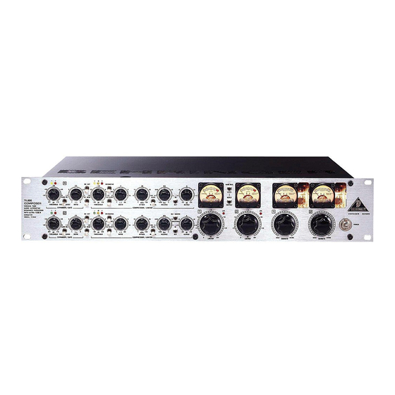
Page 8: Control Elements
1.3 Control elements Fig. 1.1: Front of the TUBE COMPOSER Fig. 1.2: Expander/gate- and compressor section CH 1 MASTER THRESHOL RATIO RELEASE... - Page 9 THRESHOLD RATIO ATTACK RELEASE Too long RELEASE time can lead to the fact that the compressor permanently attenuates the signal, without the signal being compressed. Remember when setting effective release times: As short as possible, as long as necessary. AUTO OUTPUT Please note when using the THRESHOLD control of the peak limiter section, that the OUTPUT control of the compressor section precedes the peak limiter section.
- Page 10 Fig. 1.3: Control elements of the peak limiter and tube sections VU METER OPERATING LEVEL GAIN RED/LEVEL LEVEL THRESHOLD When you use the peak limiter as a protective device against signal peaks, the THRESHOLD control should be set in combination with the OUTPUT control in the compressor section so that the peak limiter responds rarely or not at all.
-
Page 11: Operation
Fig. 1.4: Back panel of the TUBE COMPOSER SERIAL NUMBER FUSE HOLDER / VOLTAGE SELECTION AUDIO IN AUDIO OUT OPERATING LEVEL SC SEND SC RETURN 2. OPERATION Main applications and initial settings... - Page 12 2.1 Compression/levelling/limiting/clipping Compression Levelling Limiting Clipping 2.2 Expander/gate section...
- Page 13 Output Gain 0 dB Threshold IRC-Curve Expander, 1:8 Noise Gate, 1:oo Input Fig. 2.1: IRC curve characteristic of the expander Basic settings of the expander/gate section Control element Setting THRESHOLD control of the expander section RELEASE switch SLOW REL. RATIO control of the expander section IN/OUT switch SC EXT switch SC MON switch...
- Page 14 2.3 Compressor section Output Gain 0 dB Threshold Ratio 2:1 Hard Knee Ratio 4:1 Limiter oo:1 IKA Curve green yellow Input Fig. 2.2: IKA characteristic of the compressor section With the threshold control completely turned to the right, the threshold value is +20 dB. Since such a value will not be reached in practice, you can use it to disable the compressor section and work exclusively with the expander/gate and limiter circuits.
- Page 15 Control element Setting IN/OUT switch SC EXT switch SC MON switch INTERACTIVE/HARD KNEE switch INTERACTIVE SC FILTER switch THRESHOLD control of the compressor section +20 dB RATIO control AUTO switch AUTO OUTPUT control 0 dB LIMITER control GAIN RED./LEVEL switch GAIN RED.
- Page 16 Peak Limiting Level Program Limiting Release Threshold Input Output 5 ms approx. 1 s 20 ms t/ms Fig. 2.3: IGC characteristic of the limiter section Basic settings of the peak limiter section Control element Setting IN/OUT switch SC MON switch LIMITER control Tab.
-
Page 17: Applications
2.6 The vacuum tube of the TUBE COMPOSER 3. APPLICATIONS 3.1 The TUBE COMPOSER in the studio 3.1.1 Controlling leakage in the studio 3.1.2 Using the TUBE COMPOSER for recording and cassette duplication... - Page 18 3.1.3 The TUBE COMPOSER in digital recording and sampling 3.1.4 Noise reduction on effects paths 3.2 The TUBE COMPOSER in live applications 3.2.1 Reducing leakage in stage mics 3.2.2 Reducing feedback in stage mics 3.2.3 The TUBE COMPOSER as a protective device Protection of a system with a passive crossover...
- Page 19 Protection of a system with an active crossover If you want to protect separate units in a multi-way active system you can use a (multi)way compressor/limiter between the electronic crossover and the amplifier(s) like the BEHRINGER MULTICOM PRO MDX4400. 3.2.4 Improving the sound of a processor system...
- Page 20 3.3 The TUBE COMPOSER as a sound effects unit 3.4 The TUBE COMPOSER in mastering 3.5 The TUBE COMPOSER in broadcast What is volume?
- Page 21 3.6 Side chain 3.6.1 The TUBE COMPOSER as “De-Esser” Control element Setting SC EXT switch SC MON switch INTERACTIVE switch SC FILTER switch THRESHOLD control +20 dB RATIO control AUTO switch ATTACK control 1 ms RELEASE control 150 ms OUTPUT control 0 dB Tab.
-
Page 22: Technical Background
3.6.3 Suppressing instruments during recording 3.6.4 Emphasizing musical instruments during recording 3.6.5 Anticipated compression 3.6.6 “Voice-Over” compression (“ducking”) 3.6.7 Triggering additional sounds from a rhythm track 4. TECHNICAL BACKGROUND... - Page 23 Jet Engine Threshold Of Pain Power Drill Machinery Hall "Loud" Office Normal Conversation Quiet Apartment Recording Studio Falling Leaves Threshold Of Audibility Fig. 4.1: Dynamic range of human hearing ⋅ 4.1 Audio dynamics 4.1.1 Noise as a physical phenomenon...
- Page 24 4.1.2 What are audio dynamics? P/dB Fig. 4.2: The dynamic range capabilities of various devices...
- Page 25 Fig. 4.3: The interactive relationship between the operating level and the headroom 4.1.3 Compressors/limiters 4.1.4 Expanders/noise gates...
- Page 26 4.2 The tubes used in the TUBE COMPOSER 4.3 Tube history...
- Page 27 4.4 Design and functional principle of tubes Fig. 4.4: Diode Fig. 4.5: Triode...
- Page 28 Fig. 4.6: Pentode 4.5 Properties of tubes Formula for calculating partial harmonic distortion Formula for calculating total harmonic distortion...
- Page 29 4.6 The best of both worlds 4.7 UTC circuit WARMTH Fig. 4.7: UTC circuit 4.8 Studio applications...
-
Page 30: Installation
Fig. 4.8: Dynamic range of various media 5. INSTALLATION 5.1 Rack mounting 5.2 Mains connection Please make sure that all units have a proper ground connection. For your own safety, it is advisable not to remove the ground connection within the units or at the supply, or fail to make this connection at all. - Page 31 Please ensure that only qualified persons install and operate the TUBE COMPOSER. During installation and operation the user must have sufficient electrical contact to earth. Electro- static charges might affect the operation of the TUBE COMPOSER! Fig. 5.1: Different plug types 5.4 Selecting the operating level 5.5 Transformer-balanced output (option)
-
Page 32: Specifications
6. SPECIFICATIONS Audio input Audio output SC input SC output System specifications Expander/gate section Compressor section... -
Page 33: Power Supply
Physical BEHRINGER is constantly striving to maintain the highest professional standards. As a result of these efforts, modifications may be made from time to time to existing products without prior notice. Specifications and appearance may differ from those listed or... -
Page 34: Warranty
(user included) will void the warranty. at its sole discretion, either repair or replace the product. 6. If an inspection of the product by BEHRINGER shows that the 2. If the warranty claim proves to be justified, the product will be defect in question is not covered by the warranty, the inspection returned to the user freight prepaid.
Need help?
Do you have a question about the T1952 and is the answer not in the manual?
Questions and answers