Table of Contents
Advertisement
Quick Links
CYBELEC SA
CYBELEC SA
RUE DES UTTINS 27
RUE DES UTTINS 27
CH - 1400 YVERDON-LES-BAINS
CH - 1400 YVERDON-LES-BAINS
SWITZERLAND
SWITZERLAND
DNC 60 PS
User Guide
Tel. ++ 41 24 447 02 00
Tel. ++ 41 24 447 02 00
Fax ++ 41 24 447 02 01
Fax ++ 41 24 447 02 01
E-Mail: info@cybelec.ch
E-Mail: info@cybelec.ch
V-DOC-60PS-EN
V-DOC-60PS-EN
Advertisement
Table of Contents

Related Manuals for CYBELEC DNC 60 PS


Summary of Contents for CYBELEC DNC 60 PS
- Page 1 DNC 60 PS User Guide CYBELEC SA CYBELEC SA Tel. ++ 41 24 447 02 00 Tel. ++ 41 24 447 02 00 RUE DES UTTINS 27 RUE DES UTTINS 27 Fax ++ 41 24 447 02 01 Fax ++ 41 24 447 02 01...
- Page 2 Information in this document is subject to change without notice, and does not represent a commitment on the part of CYBELEC SA. The software described in this document is furnished under a license agreement or nondisclosure agreement. The software may be used or copied only in accordance with the terms of the agreement. It is against the law to copy the software on any medium except as specifically allowed in the license or nondisclosure agreement.
-
Page 3: Safety And Maintenance Instructions
AFETY AND AINTENANCE NSTRUCTIONS The operator must be trained for working with the machine on which the numerical control is installed. Improper use of the numerical control can cause heavy damage on equipment and/or injuries to people. Modification of machine parameters can cause important material damage or lead to irregular product quality. - Page 4 This page has been left blank intentionally. PAGE II USER GUIDE DNC 60 PS...
-
Page 5: License Agreement For Cybelec Software
Unauthorized copying, duplicating, selling or otherwise distributing this product is a violation of the law. PECIAL EPROM COPYRIGHT The CYBELEC DNC and CNC units in which the original software made by CYBELEC has been replaced by a copy not made by CYBELEC, and without written authorization of CYBELEC, will immediately lose their warranty. - Page 6 The foregoing warranty is instead of all other warranties, expressed or implied. Licensee further agrees that CYBELEC shall not be liable for any lost profits, lost savings, loss of use, or other incidental or consequential damages arising from the use or inability to use the software, or for any claim or demand against licensee by any other party.
- Page 7 CYBELEC during the maintenance period. In no event shall CYBELEC be obliged to provide technical support in attempting to resolve problems or difficulties resulting from licensee's modification of the licensed software; any such modification by licensee is entirely at licensee's own risk.
- Page 8 This page has been left blank intentionally. PAGE VI LICENSE AGREEMENT...
-
Page 9: Table Of Contents
SAFETY AND MAINTENANCE INSTRUCTIONS................I LICENSE AGREEMENT FOR CYBELEC SOFTWARE ..............III Safety, Copyright & License agreement ................3 CONVENTIONS ..........................5 Typographical conventions ....................5 Abbreviations / glossary.......................5 DESCRIPTION OF THE DNC 60 PS ....................7 General information ......................7 Technical characteristics .....................8 ACCESSORIES..........................11 THE USER INTERFACE........................13 The screen...........................13 The keyboard........................13... - Page 10 THE MACHINE WORKING MODES....................57 Adjustment mode........................ 57 Sensitive mode ........................58 Automatic mode........................58 PROTECTION OF THE ACCESS LEVELS ..................59 General Information ......................59 The users ..........................60 Access by password ......................61 Access to levels superior to 3 ..................... 62 Change password .......................
-
Page 11: Safety, Copyright & License Agreement
Go to page 21. This manual is evolutive. You, the user, can help us to give you better assistance. If you have any remarks on this document, please write us to: CYBELEC S.A. Dpt Communication Rue des Uttins 27 CH-1400 Yverdon-les-Bains... - Page 12 This page has been left blank intentionally. PAGE 4 FOREWORD...
-
Page 13: Conventions
ONVENTIONS As a general rule, in this manual we will not repeat how to validate a field, select a tool, call a page or any other basic manipulations. These informations are described at the beginning of this manual. YPOGRAPHICAL CONVENTIONS Arial bold Quotations of text as seen on the screen. - Page 14 This page has been left blank intentionally. PAGE 6 USER GUIDE DNC 60 PS...
-
Page 15: Description Of The Dnc 60 Ps
DESCRIPTION OF THE DNC 60 PS ENERAL INFORMATION ! Configurable numerical control for 2 to 6 axes. ! 2 synchronized numerical axes for controlling the beam (left Y1 and right Y2 jacks). ! 1 to 2 numerical axes to control the backgauge. -
Page 16: Technical Characteristics
0 - ±99,99 mm ACKGAUGE AXIS Positioning range 0 - 2000,000 mm Programmable resolution 0,1 or 0,01 mm Reproducibility 0,02 mm Displacement speed 500 mm/s Corrections per product and per sequence : 0 - ±99,99 mm PAGE 8 USER GUIDE DNC 60 PS... - Page 17 ! Quantity of products made and to be made. Unattributed functions: F1 to F3: Analogical function 250 values with bi-directional positioning (backgauge height, bending help, etc) F4 and F5: digital (BCD coded output) DESCRIPTION OF THE DNC 60 PS PAGE 9...
- Page 18 The DNC 60 is equipped with a Flash memory including the program and the cycle of the numerical control. The machine cycle can be updated by means of the serial link RS232 (option). PAGE 10 USER GUIDE DNC 60 PS...
-
Page 19: Accessories
DNC 7000, DNC 70, DNC 50 and DNC 60. LINK7000 Option of the software PC900 / PC1200 to transfer products to the DNC 7000, DNC 70, DNC 50 or DNC 60 by the serial line. DESCRIPTION OF THE DNC 60 PS PAGE 11... - Page 20 This page has been left blank intentionally. PAGE 12 USER GUIDE DNC 60 PS...
-
Page 21: The User Interface
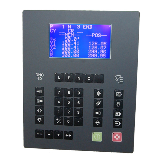
HE USER INTERFACE HE SCREEN The screen displays the products, tools and machine parameters as well as all other useful information for programming and machine work. The keys situated on the front of the DNC are used for selecting the screen pages and introducing data. - Page 22 Pressing a third time displays the second page of values and functions in large characters. Correction key This key displays the correction page which allows to make corrections to the current sequence, as well as to the entire product. PAGE 14 USER GUIDE DNC 60 PS...
- Page 23 HE WORKING MODES Programming mode Allows to introduce, modify and read data as well as to store, search for and transfer programs. Manual mode Authorizes axis movement and auxiliary functions using the keys. Semi-automatic mode Allows a machine cycle with the current sequence values without automatic sequence change.
- Page 24 (teach) the value of an axis positioned manually in the current sequence. This key is only valid in programming (memorization and insertion) mode and in manual (teach) mode. PAGE 16 USER GUIDE DNC 60 PS...
- Page 25 HE CURSOR KEYS Sequence forwards / Page forwards key This key allows to scroll pages of the same type. Also allows to pass to the next page when a series of information occupies several pages. Eg.: program sequence punch-die pages production pages parameter pages In programming mode also allows to create an...
- Page 26 STOP key allows to terminate the transfer. Manual displacement keys of the selected axes. Allows, in the machine parameters, to configure the axis type, the inputs/outputs and to select the display of the N2X axes. PAGE 18 USER GUIDE DNC 60 PS...
-
Page 27: The Main Menu
HE MAIN MENU By pressing the key on the top right of the keyboard, the main menu appears. CHOICE ? LIST OF PRODUCTS DNC / CRITERIA LIST OF PUNCHES LIST OF DIES PROGR. PUNCHES / DIES PRODUCT PUNCHES / DIES PRODUCT STATUS;... - Page 28 Displays a series of pages which allow to introduce, display and modify the machine parameters. PARAMETERS 14 MACHINE Page allowing to control and to modify the state of certain inputs and outputs. CONTROLS PAGE 20 USER GUIDE DNC 60 PS...
-
Page 29: Programming
ROGRAMMING In this manual, it is being assumed that the DNC is configurated in such a way to be operational (i.e. the tools and machine parameters have already been programmed). 2 programming methods are accessible by the operator. With unfolding calculation ! The L-alpha method. - Page 30 Consulting the list of dies Proceed in the same way as described above for punches; access from the main menu LIST OF DIES. Pass to page 27 or page 40, depending on the chosen programming method. PAGE 22 USER GUIDE DNC 60 PS...
-
Page 31: Programming On The L-Alpha Page
ROGRAMMING ON THE ALPHA PAGE The PRODUCT STATUS page is often called L-alpha page for its programming method. On this page, a product is programmed by defining its profile by the length and the angle of each face. Call the L-alpha page using the key, or by passing via the main menu choosing PRODUCT STATUS. - Page 32 If no field is programmed, steel is used by default. Material thickness. Kg/mm² (Sigma) Tensile strength. Lmat Bending length. Unfolded length of the product calculated by Dev L the system according to DIN 6935 standard. PAGE 24 USER GUIDE DNC 60 PS...
- Page 33 L-alpha page : Explication of the columns Each line (except the last) of the table on the PRODUCT STATUS page represents data related to one bend. -p/d- -ri- CR TOL 1 ____.__ ____._°__/__ ____.__ __ ___ 2 ____.__ ____._°__/__ ____.__ __ ___ 3 ____.__ Automatic numbering of the faces.
- Page 34 A of the chord. ri = Theoretical bending radius requested by the operator. A = Apex. For an example of ideal curve, see Ideal curve, page 77. PAGE 26 USER GUIDE DNC 60 PS...
-
Page 35: L-Alpha Method
ALPHA METHOD If you have it not already on screen, call the PRODUCT L-alpha page. The screen displays the data concerning the product in the work memory at present. In order to program a new product, the work memory must be cleared by deleting the product already there. - Page 36 __ ___ After introducing the last length, press the key. The system calculates the radius of each bend as well as the unfolded length of the product and displays these values on the screen. PAGE 28 USER GUIDE DNC 60 PS...
- Page 37 Save this product in the internal memory by proceeding as follows: ! Introduce the number you wish to give the product in the P field, in this case the number 1 for this product which will be used later as an example.
-
Page 38: Definition Of The Bending Order
Number of bends requested when working with ideal curve. Definition of a tooling pair for a particular bend (if different from the pair specified in the p/d field at the top of the page). PAGE 30 USER GUIDE DNC 60 PS... - Page 39 Example a For this example we will use the previously created product. It was stored under the number 1. (If you cannot find it, create it by following the instructions of page 27). ! Call the product number 1 by entering its number in the P field, and then pressing the key.
- Page 40 (See the Sheet metal manipulation diagram below). FACE 1/ 1 1/ 1 RETURN 1/ 1 1/ 1 SWIVEL Fig. Sheet metal manipulation Return Swing Swivel (= Swing 180° + return) PAGE 32 USER GUIDE DNC 60 PS...
- Page 41 ! By pressing the key, you can consult the PRODUCT; ; Y page which displays for each sequence the X and Y axes' values (the values depend on the used material and tools). 78.06 90.0° 229.90 145.51 135.0° 233.58 __ RETURN 58.06 90.0°...
- Page 42 The system calculates the entire machine program (axes, functions, etc.) and displays the sheet metal manipulations to be made before each sequence. FACE 1/ 1 1/ 1 1/ 1 RETURN 1/ 1 PAGE 34 USER GUIDE DNC 60 PS...
- Page 43 ! By pressing the key, you can consult the PRODUCT; X; ; Y page. This page displays for each sequence the X and Y axes' values (the values depend on the used material and tools). 305.42 135.0° 233.58 78.06 90.0° 229.90 58.06 90.0°...
- Page 44 This page has been left blank intentionally. PAGE 36 USER GUIDE DNC 60 PS...
-
Page 45: The Sequence Page
HE SEQUENCE PAGE This page displays all the bending informations for the current sequence. That is the requested position of the Y and X (R, etc.) axes, the pressure, the gauge retraction, the crowning, the dwell time, etc. Important This page displays the result of the calculations made when programming a product in the L-alpha page with definition of the bending order. - Page 46 _ = the beam stops at the CP and waits till the retraction is made, in order to carry out the bend. 1 = the beam stops at the CP, then continues immediately, at the same time as the retraction is carrying out. PAGE 38 USER GUIDE DNC 60 PS...
- Page 47 Ext start If nothing is programmed in this field, the axes start automatically from the BDC, from the CP or from the TDC, depending on the choice made in the machine parameters. If 1 is programmed, the start will be made as a function of the configuration made by the constructor.
-
Page 48: Programming On The Sequence Page
IRECT PROGRAMMING Programming example The following product is to be realized: 2.0 mm Lmat: 1000 mm The bending order is the following: ! Bend 1 on FACE 1 and LEG 0 PAGE 40 USER GUIDE DNC 60 PS... - Page 49 ! Bend 2 on FACE 3 and LEG 4 ! Bend 3 on FACE 2 and LEG 3 ! Call the sequence page. ! Clear the work memory. Place the cursor in the N field (reminder: to position the cursor on the top of the page). Introduce 99 and press the key.
- Page 50 --MEM-- --POS-- --COR-- 90.0° 229.90 350.92 ____.__ 229.90 351.05 ____.__ 58.00 51.85 ____.__ ____ ____ Lmat 1000 Ext start _ ∆ ∆ ∆ ∆ T _._s F1:___ F2:___ F3:___ F4:__ F5:__ Cr: 41 PAGE 42 USER GUIDE DNC 60 PS...
- Page 51 Modify the values which are different for this sequence, in this case enter 18 in the X field. CY __ 2.00 37.00 Kg/mm² 1/ 1 CR __/ri __.__ --MEM-- --POS-- --COR-- 90.0° 229.90 350.92 ____.__ 229.90 351.05 ____.__ 18.00 51.85 ____.__ ____ ____...
- Page 52 It will, however, remain present in the work memory. ! Pass to semi-automatic mode ! Call the sequence 1. ! Execute the first bend. ! For corrections pass to page 80. PAGE 44 USER GUIDE DNC 60 PS...
-
Page 53: Product Management
RODUCT MANAGEMENT This chapter indicates how to manage the products (programs) stored in the numerical control. IST OF PRODUCTS ! Press the key. CODE 623-42.15 SEQUENCES PROGRAMMED AVAILABLE -LIST OF PRODUCTS IN MEMORY- 11 222 997 ___ ___ ___ ___ ___ ___ ___ ___ ___ ___ ___ ___ ___ ___ ___ ___ ___ ___ ___ ___ ___ ___ ___ ___ ___ ___ ___ ___ ___ ___ ___ ___ ___ ___ ___... - Page 54 Saving a product is possible from all pages on which the cursor can be placed on the P field. It should be noted that after saving the product remains present in the work memory. To save a product proceed as follows: PAGE 46 USER GUIDE DNC 60 PS...
- Page 55 ! If you wish to give a drawing number or name to the product, fill in the CODE field. This operation is optional. ! Enter the number of the product in the P field. ! Leave the cursor in the P field. ! Press the key.
- Page 56 This page has been left blank intentionally. PAGE 48 USER GUIDE DNC 60 PS...
-
Page 57: Tool Programming
OOL PROGRAMMING The DNC 60 has several pages which allow consultation of the list of existing tools, to display them and / or program new ones. The DNC 60 memory can hold a maximum of 20 punches and 30 dies. IST OF PUNCHES ! From the main menu choose option LIST OF PUNCHES. -
Page 58: Punch / Die Programming
See Erreur ! Résultat incorrect pour une table.. SAF X X Safety distance. (Not programmed = half V opening) a: and b: Table and die dimensions according to the drawing displayed on the screen. PAGE 50 USER GUIDE DNC 60 PS... - Page 59 ROGRAMMING A PUNCH ! On the PUNCH / DIE PROGRAMMING page, delete the values on this page by pressing the key twice. ! Fill in the different fields. ! If you wish to save this new punch proceed as follows: a) Place the cursor on the PROGR.
- Page 60 ! Introduce the number of the punch to be deleted in the p/ field. ! Press ROGRAMMING A DIE The programming of a die is done in the same way as for a punch, but in the /m field. PAGE 52 USER GUIDE DNC 60 PS...
-
Page 61: Transfer
RS232 option. . Products The PC must be equipped with the CYBELEC PC900 / PC1200 software with option LINK7000. This unity allows to create products in the bending software on PC and to transfer them to the DNC for execution. -
Page 62: Tests Of The Serial Ports
Pin 4 (DTR) wired to pin 6 (DSR) Pin 7 (RTS) wired to pin 8 (CTS) RS 232 transmission cable The shield must be connected on the metallic hood of the Sub-D plugs. PAGE 54 USER GUIDE DNC 60 PS... -
Page 63: Link 7000 / Cyback
LINK 7000 / CYBACK For these two programs the RS cable must be connected on the RS232 port of the J5 plug. The transmission parameters must be programmed on the DNC with the same values as for the test of the serial ports (see paragraph above). These same values must be programmed on the PC. - Page 64 This page has been left blank intentionally. PAGE 56 USER GUIDE DNC 60 PS...
-
Page 65: The Machine Working Modes
HE MACHINE WORKING MODES 3 working modes are generally available at machine level. The functioning is described hereinafter. Depending on the manufacturers and the safety standards in force in the country, the functioning can be different. Adjustment mode Sensitive mode Automatic mode These modes are independent of the DNC modes and can... -
Page 66: Sensitive Mode
This even if the descent command remains active. In all these modes the ascent command has priority. It is executed immediately on its reception. PAGE 58 USER GUIDE DNC 60 PS... -
Page 67: Protection Of The Access Levels
ROTECTION OF THE ACCESS LEVELS ENERAL NFORMATION Depending on the version, the DNC 60 can or can not be equipped with a 4-positions physical key. However the protection levels 0-1-2 and 3 still exist. For the case where the physical key doesn't exist, the access is made by password. -
Page 68: The Users
After installing the machine it is advised to modify the password by default of level 4 (WSSUPER = Workshop supervisor) and of level 3 (EUL3 = Operators with authorization level 3), because the passwords are in this manual. PAGE 60 USER GUIDE DNC 60 PS... -
Page 69: Access By Password
CCESS BY PASSWORD By starting the software, the virtual key is always positioned at 0. ! Choose the level to access by pressing one of the combinations ! The message VALUE ? appears. ! Introduce the password and press the key to validate the password. -
Page 70: Access To Levels Superior To 3
If his access level enables him, he can call the procedure of password modification (see next paragraph). ! At the end of the intervention, don't forget to pass to level 0 in order to leave the current level. PAGE 62 USER GUIDE DNC 60 PS... -
Page 71: Change Password
HANGE PASSWORD It is possible to modify the passwords attributed by default. Certain users can do it for themselves, others not. In order to know the authorizations, see Table of users, access and passwords. To change a password: ! Press the keys combination ! The message LEVEL ? appears. -
Page 72: Management Of The Access Levels By External Key
The use of the external key is defined by the parameter Key = 1 and by the use of the inputs KEY 0 and KEY 1. Input Input Pos. KEY 0 KEY 1 PAGE 64 USER GUIDE DNC 60 PS... -
Page 73: Annexes
This page appears if a calculation is impossible, due to unprogrammed data or an incorrect value. It can also appear as a result of pollution of one of the memory zones which will also give impossible calculations. INITIALIZATION DNC 60 PS -- MEMORY ZONE -- Clear variables zone Clear punches-dies zone... - Page 74 The best to do in this case is to delete again the whole contents of the DNC and to re-program the DNC manually via the keyboard (not the RS232 line). PAGE 66 USER GUIDE DNC 60 PS...
-
Page 75: The Tool Reference
HE TOOL REFERENCE The machine has been adjusted according to the following principle: When, theoretically, the punch's leg face on the beam is in contact with the surface of the table, the value of the Y1 and Y2 counters is 000.00. In practice this adjustment is made using two calibrated blocks, whose value has been introduced into the counters. - Page 76 (which will not bend under the weight of the beam) or blocks of a known precise thickness, (see figure below). The value of the material introduced between the punch and the die must then be subtracted to obtain the reference value REF Y. PAGE 68 USER GUIDE DNC 60 PS...
- Page 77 Y1 and Y2 counters greatly different If the counters are not identical and present a difference superior to what is normally tolerated (the press in this case furnishes an angle which varies from one side to the other of the machine), a test must be made with another tool in order to determine if the difference comes from the tool itself (tool badly finished presenting a difference in height along its length) or if the press is badly calibrated.
-
Page 78: The Contact Point (Cp) Or Pinch Point
For the softwares having the "CP correction" parameter, if the reference, the tooling dimensions and material thickness are correct you can modify this parameter in order to correct the CP (adjustment of the material clamping) without interfering with the other points. PAGE 70 USER GUIDE DNC 60 PS... -
Page 79: The Gauge Axes
HE GAUGE AXES The addition of supplementary axes (to X) does not present any difficulties for the operator, the fields being clearly defined on the screen. The safety factors concerning the supplementary axes such as R, X1, X2, Z1 and Z2 are described below. X-R safety factors When the R axis is a digital axis, an anti-collision safety factor prohibits the positioning of the gauge probes in the die. - Page 80 = "a" die value = "hm" die value = Xo + X"o = Ro + R"o = X axis current value = R axis current value = X axis target value = R axis target value PAGE 72 USER GUIDE DNC 60 PS...
- Page 81 Two examples of positioning These two examples show that it is possible to position in the safety zone. If the positioning requested is situated in the prohibited zone, the DNC refuses to go into mode and the cursor moves to the X field. Xv >...
- Page 82 "Z1-Z2" is obtained if the positioning is impossible (see parameter 51). Normally the origin of the Z axes is on the left of the machine when looking at the front of the machine. PAGE 74 USER GUIDE DNC 60 PS...
-
Page 83: Programming The Axes Datum
ROGRAMMING THE AXES DATUM Select option 11 of the main menu, the following page appears: AXES DATUM --SET-- --POS-- X _____.__ 0.00 Y1 ____.__ ____.__ Y2 ____.__ ____.__ ! Introduce in the SET column the values for the axes datum. ! Leave the field for validation. - Page 84 N1. To leave this work mode, clear the CAL field using the key. If any modifications are made to the tools, it will be necessary to repeat the calibration. PAGE 76 USER GUIDE DNC 60 PS...
-
Page 85: Ideal Curve
DEAL CURVE The ideal curve allows to make a bend with a large internal radius. An ideal curve can be programmed on one or the other of these pages. An ideal curve is defined by programming from 4 to 98 (programming 0, 2 or 3 will give an error). - Page 86 LEG and FACE fields as below. 1/ 1 FACE 1/ 1 1/ 1 Attention The X MEM values on the sequence page do not correspond to the position actually aimed for by the axis during ideal curve. PAGE 78 USER GUIDE DNC 60 PS...
-
Page 87: Cycle Without Bend
YCLE WITHOUT BEND The cycle without bend is used to move the axes and auxiliary functions without moving the beam. To program a cycle without bend: ! Delete the field. ! Program Y1 and Y2 at a value greater than that of the contact point (CP). -
Page 88: Bottoming
Call the CORRECTION page by pressing the key. The passage to the following or previous bend is made by using the keys. CY __ -COR N- -COR P- 90.0° ___._° ___._° ___.__ ___.__ ___.__ ___.__ ___.__ ___.__ PAGE 80 USER GUIDE DNC 60 PS... - Page 89 COR N This column allows to make a correction for the current sequence only. (The wording COR N may possibly not appear according to the machine configuration, however it concerns always the fields of the left column). COR P This column allows to make corrections on the whole product in one single operation.
-
Page 90: Alphanumerical Characters
If another error exists the process repeats itself until all the errors have been corrected. By error we understand the programming of a value not realizable by the DNC (further than the limit switches, collision, etc.). PAGE 82 USER GUIDE DNC 60 PS... -
Page 91: The Interactive Messages
HE INTERACTIVE MESSAGES CASSETTE Indicates that the "cassette" (internal memory) - has not been initialized - is polluted - has changed the format (e.g. by changing the software version). Just "clean" the internal memory by placing the cursor on the P field, entering 999 and pressing the key. - Page 92 30 seconds. TOL ZONE Displayed in mode when the axes are positioned outside of their tolerances. Generally, just press the start of the front pannel to position the axes will do. PAGE 84 USER GUIDE DNC 60 PS...
- Page 93 UNDEFINED Refusal to change to , if the parameters vital to execution are not or only partially programmed and thus prevent the verification calculations. Var KO One of the DNC inputs "SERVO DRIVER OK" is not (no longer) active (+24 VDC). ANNEXES PAGE 85...
-
Page 94: Print Of The Current Screen
0 (2 space characters) to 9 (20 space characters) Example: BCC = 4, then 2 + (4 x 2) = 10 O PRINT FROM THE ! Select the relevant page. ! Simultaneously press the stop and correction or menu keys. PAGE 86 USER GUIDE DNC 60 PS... -
Page 95: Index
INDEX work memory, 41 Conventions, 5 Copy Abbreviations, 5 sequence, 37, 42 Access Copyright & License agreement, 3 by password, 59, 61 to levels superior to 3, 62 Correction, 14 angle, 80 Access levels, 59 page, 80 Management by external key, 64 use the page, 37 Protection, 59 Users, 59... - Page 96 Kg/mm², 24 Memory L, 25 buffer, 10 LEG, 30 Flash, 53 Lmat, 24, 38 internal, 10 MEM, 38 internal cassette, 10 N, 24, 25, 38 work memory, 10 P, 23 Memory zone, 65 p/d, 24 P+, 24 Menu POS, 38 key, 14 Q, 38 Message...
- Page 97 angle, 50 linear force, 50 Teach reference, 67 key, 16 Punching, 79 Thickness measuring, 76 Tooling, 49 REF Y, 50 Tools reference, 67 Reference, 67 Transfer, 53 Return, 32 RS232, 53 transmission cable, 54 Updating, 53 Rules conventions, 5 Users, 59 table of ..., 60 SAF X, 50 Safety, 71...
Need help?
Do you have a question about the DNC 60 PS and is the answer not in the manual?
Questions and answers
Ayarlamada makinayi aç kapat yaptım ekrandan yazılar gitti nasıl düzeltebilirim
To fix the display issue on the CYBELEC DNC 60 PS after turning the machine on and off, follow these steps:
1. Switch the machine off and then on again.
2. Check the program to ensure safety factors are correctly set.
3. Verify that the axes can move in manual mode.
4. Compare the machine parameters with the written list to ensure they are correct.
If the issue persists, you may need to clear and reconfigure the machine parameters by:
1. Setting the following values:
- Clear variables zone: 1
- Clear punches-dies zone: 1
- Clear machine parameters zone: 1
- EXECUTION CODE: 817
2. Pressing the key twice to confirm.
After clearing, reconfigure the DNC 60 before using it again. If using an external system (CYBACK via RS232) for data re-entry and the problem continues, delete all DNC contents and manually reprogram it via the keyboard instead of RS232.
This answer is automatically generated
@Mr. Anderson
Makinanı nasıl yeniden başlatıcam ekran yazıları gitti geri getiremiyorum
To restart the CYBELEC DNC 60 PS machine when the screen text is missing, follow these steps:
1. Switch the machine off, then turn it on again.
2. Check the program, ensuring the safety factors are correct.
3. Verify that the axes can be moved in manual mode.
4. Compare the machine parameters with the written list.
If the issue persists, consider clearing the machine parameters and reconfiguring the DNC 60 manually via the keyboard instead of using an external system like CYBACK via RS232.
This answer is automatically generated
I want out and in put terminals details of DNC 60 ps8