Table of Contents
Advertisement
Talk to us. We listen.
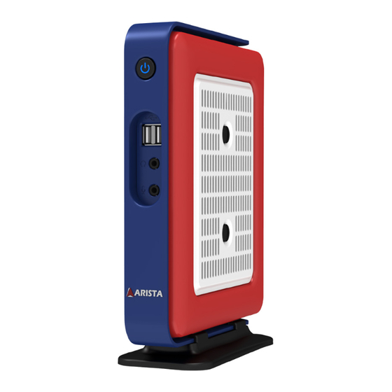
AP-3500-E01 Office Thin Client
This manual is a user guide for AP-3500-E01 Office Thin Client. It includes
detailed description about how to install and operate the product. Arista
Corporation recommends users to read through the entire manual and
follow instructions to avoid any kind of obscurity in using the product.
For any questions or support, please call us at 1.877.827.4782 Monday
through Friday 8:00am to 5:00PM Pacific Time.
Publication date: 2016/10/25
Version No.: V2.2
Advertisement
Table of Contents

Related Manuals for Arista AP-3500-E01


Summary of Contents for Arista AP-3500-E01
- Page 1 Talk to us. We listen. AP-3500-E01 Office Thin Client This manual is a user guide for AP-3500-E01 Office Thin Client. It includes detailed description about how to install and operate the product. Arista Corporation recommends users to read through the entire manual and follow instructions to avoid any kind of obscurity in using the product.
-
Page 2: Product Safety Precautions
Ensure that the power source is grounded correctly. • Unplug the unit if cleaning is needed. The unit may be wiped down with a dry or slightly damp cloth when the power is off. Important: Read all the contents of this instruction manual carefully before using the AP-3500-E01 Office Thin Client. -
Page 3: Table Of Contents
Contents Contents Product safety precautions ....................2 Contents ..........................3 Chapter 1 Welcome ......................4 Features..........................4 Product specifications ....................5 Unpacking ........................6 Chapter 2 Basics.........................7 Product overview.......................7 Physical dimensions ....................9 Chapter 3 Connections ....................10 Pins in the Serial port (COM1)...................11 Mounting the Thin Client....................12 Connecting to a display....................15 Connecting to keyboard or mouse................15 Connecting to network....................16... -
Page 4: Chapter 1 Welcome
Features Arista AP-3500-E01 thin client is a lightweight computer that is purpose-built for remote access to a server (typically cloud or desktop virtualization environments). Thin clients occur as components of a broader computing infrastructure, where many clients share their computations with a server or server farm. The server-side infrastructure makes use of cloud computing software such as application virtualization, hosted shared desktop (HSD) or desktop virtualization (VDI). -
Page 5: Product Specifications
Product specifications System Intel E3845 1.91GHz ATOM CPU Chipset (By CPU) Memory Up to 8GB DDR3 SO-DIMM Video controller Intel Gen7 Intel Graphics DX 11, OGL3.2 Video interface Dual HDMI Storage option SATA DOM, 2.5" HDD, 2.5" SSD Compact flash Keyboard/Mouse Audio Mic In, Line Out Watchdog Timer... -
Page 6: Unpacking
Unpacking The unit is shipped with items listed below, inspect them carefully to make sure there is no damage and all the items are available with your shipment. AP-3500-E01 Thin Client AC/DC power adapter AC power cable x1 AC power cable... -
Page 7: Chapter 2 Basics
Chapter 2 Basics Product overview AP-3500-E01 Office Thin Client Side Side Front Bottom... - Page 8 1. Power button 6. 2 x HDMI ports 2. 2 x USB ports 7. COM port 3. Earphone/Headphone jack 8. 2 x RJ45 LAN ports 4. Microphone jack 9. DC 12V/3A power jack 5. 2 x USB ports 10. Desktop stand base(removable) LED Indications on the LAN port Status Description...
-
Page 9: Physical Dimensions
Physical dimension The diagrams below show the physical and specific dimensions of the AP-3500-E01 Thin Client. AP-3500-E01 Office Thin Client 182.0mm 7.17" 70.5mm 2.77" 44.6mm 1.76" 32.0mm 1.26" 222.0mm 8.74" 236.5mm 9.31" 152.2mm 5.99"... -
Page 10: Chapter 3 Connections
Chapter 3 Connections This section describes the connections/connectors available on the AP-3500-E01 Office Thin Client. Connectors are located on the side of AP-3500-E01 Thin Client. -
Page 11: Pins In The Serial Port (Com1)
Pins in the serial port (COM1) 1 2 3 4 5 6 7 8 9 Pin NO. Definition(RS-232 mode) Definition(RS-422/RS-485 mode) DCD, data carrier detect TX-, Transmit data ground (RS-422/RS-485) RXD, Receive data TX+, Transmit data(RS-422/RS-485) TXD, Transmit data RX+, Receive data (RS-422) DTR, Data terminal ready RX-, Receive data ground (RS-422) GND, Signal ground... -
Page 12: Mounting The Thin Client
Mounting the Thin Client Desktop mounting The AP-3500-E01 Office Thin Client can be directly placed on a shelf or table by using desktop stand base(supplied with the unit). Please follow the steps shown in the diagram below: Step1. Place the bottom side of AP-3500-E01 Office Thin Client within the place on the desktop stand base where there are four mounting clips. -
Page 13: Vesa Mounting
Display back panel Screw holes Step2. Align the four mounting screw holes on the AP-3500-E01 VESA bracket with the screw holes on the display. Tighten the four screws with a screw driver to fix the VESA bracket onto the display. - Page 14 If the AP-3500-E01 Office Thin Client is desktop mounted, please slide the desktop stand base out to remove it from the unit. Step4. Snag the white bottom base of the AP-3500-E01 Office Thin Client with the two Spring hooks on the VESA bracket installed on the display. Make sure the AP-3500-E01 Office Thin Client is correctly and securely seated onto the display.
-
Page 15: Connecting To A Display
Client. Connect the other end of the HDMI cable to the HDMI port of a display. AP-3500-E01 Display HDMI port HDMI port HDMI cable(not supplied) Connecting to keyboard and mouse • Insert a USB keyboard and a USB mouse(not supplied) to AP-3500-E01 Office Thin Client for controlling on the computer. USB port AP-3500-E01 Mouse Keyboard... -
Page 16: Connecting To Network
RJ45 LAN cable(not supplied) Connecting earphones or speaker • Connect the earphone end of the audio cable to the Earphone jack of the AP-3500-E01 Office Thin Client. Connect the microphone end of the audio cable to the Microphone jack of the AP-3500-E01 Office Thin Client. Also, you can connect to a speaker by connecting to the Earphone jack of the AP-3500-E01 Office Thin Client. -
Page 17: Connecting The Power Supply
Follow the steps below to connect the power supply. • Connect one end of the 12V AC/DC power adapter to the DC-in(12V) power connector of the AP-3500-E01 Office Thin Client. Connect the other end of 12V AC/DC power adapter to an AC outlet. -
Page 18: Installing Memory Module/Expansion Card
1. As shown in the figure below, remove the two screws at the center of the bottom cover. 2. Then remove the bottom cover of the AP-3500-E01 Office Thin Client and a metal protection base, you will find the DDR3 SO-DIMM slot, MINI_PCIE slot and CFast card slot on the motherboard. -
Page 19: Removing The Memory Module
Follow the steps outlined below to install the SO-DIMM. 1. Locate the DIMM on the SO-DIMM slot and align the notch on the DIMM with the key on the slot. Note: DO NOT force a DIMM into a slot to avoid damaging the DIMM. DIMM The notch on T h e k e y o n... -
Page 20: Installing Cfast Card
Installing CFast card Removable memory storage is available on computer with Arista B048 motherboard. The storage is in the form of a CFast memory card( a compact SATA SSD that comply with CFast. CFast card slot supports CFast TypeI/II card. Orient the CFast card so that the notch on the card aligns with the key on the slot(See Figure1 and Figure2). -
Page 21: Installing Expansion Card
Installing expansion card The MINI-PCIE slot supports PCIE cards such as a Wi-Fi LAN card, mSATA SSD, SCSI card, USB card, and other cards that comply with PCIE specifications. Step 1. Before installing the expansion card, please make sure that the power supply is switched off and the power cord is unplugged. Please read the documentation of the expansion card and make necessary hardware settings for the card before you start the installation. -
Page 22: Clearing Cmos Data
Clearing CMOS data As shown in the figure below, this jumper allows you to erase CMOS data and reset setting to factory default. Normally this jumper should be set with pins 1-2 closed. If you want to reset the CMOS data, set the Clear CMOS jumper to 2-3 closed for just a few seconds, and then move the jumper back to 1-2 closed. This procedure will reset the CMOS data to its default settings. -
Page 23: Chapter 4 Bios Setup
Chapter 4 BIOS Setup Introduction The computer uses the latest “American Megatrends Inc. ” BIOS with support for Windows Plug and Play. The CMOS chip on the motherboard contains the ROM setup instructions for configuring the built-in motherboard BIOS. The BIOS (Basic Input and Output System) Setup Utility displays the system’s configuration status and provides you with options to set system parameters. The parameters are stored in battery-backed-up CMOS RAM that saves this information when the power is turned off. When the system is turned back on, the system is configured with the values you stored in CMOS. -
Page 24: Entering The Setup
Entering the Setup When you power on the system, BIOS enters the Power-On Self Test (POST) routines. POST is a series of built-in diagnostics performed by the BIOS. After the POST routines are completed, the following message appears: Press the Delete key to access BIOS Setup Utility. Resetting the default CMOS values When powering on for the first time, the POST screen may show a “CMOS Settings Wrong”... -
Page 25: Bios Navigation Keys
The default BIOS setting for this built-in motherboard apply for most conditions with optimum performance. We do not suggest users change the default values in the BIOS setup and take no responsibility to any damage caused by changing the BIOS settings. BIOS navigation keys The BIOS navigation keys are listed below: FUNCTION... -
Page 26: Main Menu
Main Menu When you enter the BIOS SETUP UTILITY, the Main menu will appear and display the system overview. You can set the system clock in this main menu. BIOS Information This item shows the current BIOS information, including BIOS Version, Build date and time. LAN1/LAN2 MAC Address Use this item to view the LAN1/LAN2 Mac address. -
Page 27: Advanced Menu
Advanced Menu This section allows you to configure and improve your system and allows you to set up some system features according to your preference. Important: The default value Be cautious when changing the setting of the Advanced menu items. Incorrect field values can cause the system to malfunction. ACPI Settings Scroll to this item and press <Enter> to view the following screen: ACPI Sleep State [S3 (Suspend to RAM)] Select the highest ACPI sleep state, the system will resume when the SUSPEND button is pressed. - Page 28 FB1216 Super IO Configuration Scroll to this item and press <Enter> to view the following screen: Serial Port1/Port2/Port3/Port4 Configuration Serial port1/port2/port3/port4(Enabled) Use this option to enable or disable the use of serial ports. Change settings(Auto) Select an optimal settings for Super IO device. Type select(RS232) Select serial port type(RS232,RS422,RS485).
-
Page 29: Cpu Configuration
CPU Configuration Scroll to this item and press <Enter> to view the following screen: Socket 0 CPU information Use this item to view Socket 0 CPU information. Intel Virtualization Technology(Enabled) Most of the time, hardware virtualization technology extensions should be enabled in motherboard BIOS in order to run recent OS and applications. -
Page 30: Ide Configuration
IDE Configuration Scroll to this item and press <Enter> to view the following screen: SATA Port1~2 dynamically detect whether there are SATA devices on motherboard. If devices are connected with the corresponding ports, then it will display the SATA device type. - Page 31 Miscellaneous Configuration Scroll to this item and press <Enter> to view the following screen: OS selection (Windows 7) Use this option to select the operating system for the computer. Press <Esc> to return to the Advanced Menu screen.
-
Page 32: Usb Configuration
USB Configuration Scroll to this item and press <Enter> to view the following screen: Legacy USB Support (Enabled) Use this option to enable USB mouse and USB keyboard support. ENABLED option enables legacy USB support. AUTO option disables legacy support if no USB devices are connected. DISABLED option will keep USB devices available only for EFI applications. -
Page 33: Chipset Menu
Chipset Menu The chipset menu allows you to change the settings for the Host Bridge chipset, South Bridge, chipset and other system.Since the features in this section are related to the chipset on the CPU board and are completely optimized, you are not recommended to change the default settings in this setup table unless you are well oriented with the chipset features. -
Page 34: Lcd Control
LCD Control Scroll to this item and press <Enter> to view the following screen: Primary IGFx Boot display (VBIOS Default) Select the video device which will be activated during POST. This has no effect if external graphics present. Secondary boot display selection will appear based on your selection. VGA modes will be supported only on primary display. -
Page 35: South Bridge
South Bridge Scroll to this item and press <Enter> to view the following screen: S5 RTC Wake Setting Wake system from S5 (Disabled) Use this option to enable or disable RTC Alarm Wake Up feature. - Page 36 Azalia HD Audio Audio Controller (Enabled) Use this option to control detection of the Azalia device. Azalia controller(Enabled) Disabled: Azalia will be unconditionally disabled. Enabled: Azalia will be unconditionally enabled. Auto: Azalia will enabled if present disabled otherwise. Onboard LAN1/LAN2(Enabled) This item allows you to enable or disable the onboard LAN1 or LAN2.
-
Page 37: Security Menu
Security Menu The Security Menu allows you to set Administrator and User password. If ONLY the Administrator’s password is set, then this only limits access to setup and is only asked for when entering Setup. If ONLY the user’s password is set, then this is a power on password and must be entered to boot or enter Setup. -
Page 38: Boot Menu
Boot Menu The Boot Menu allows you to change the system boot options. Bootup Num-lock state (ON) If this item is set to “On”, it will automatically activate the Numeric Lock funcition after boot-up. Quiet Boot (Enabled) This item allows the bootup screen options to be modified between POST messages or the OEM logo.Select “Disabled” to display the POST messages. Select “Enabled” to display the OEM logo instead of the normal POST messages. -
Page 39: Save&Exit Menu
Save & Exit Menu The Save & Exit Menu allows you to save the changes that you have made in the Setup Utility and exit the Setup Utility. Save Changes and Exit When you select this option, it will pop-out the following message, “Save configuration changes and exit setup?”... -
Page 40: Chapter 5 Appendix
• Keep the AP-3500-E01 Office Thin Client in a dry, clean space. Make sure the unit has minimal exposure to dust - don’t get the power switches or other controls wet. • If the AP-3500-E01 Office Thin Client gets wet, power it off immediately. Wait for the AP- 3500-E01 Office Thin Client to dry completely before powering it on again. -
Page 41: Product Limited Warranty
(invoice date),Arista Corporation will repair or replace with new or refurbished product or parts. • Arista Corporation holds every right to decide for repair or replacement of any product or part. During the “labor” limited warranty period there will be no charge for labor and during the “parts”... - Page 42 If shipment of missing items or replacement of wrong items is requested, Arista will ship the replacement in 7 calendar days. A credit memo will be issued to the customer after the returned product is received and verified.
- Page 43 • No Credit DOA: No credit will be given to the customer for DOA products re-ceived by Arista beyond 30 calendar days after the invoice date. No credit will be given to all non- cancellable, non-returnable, custom order parts.
- Page 44 7. RMA Transportation Policy Product Non-Acceptance • Products will not be accepted by Arista Corporation if not accompanied by a valid RMA number, which must be clearly marked on the outside of the package. • Any products refused by Arista will incur the fees and/or charges applied by the shipping carrier, and shall be the sole liability of the original shipper.
-
Page 45: Customer Responsibilities
• Arista Corporation is not liable for incidental or consequential damages resulting from the use of Arista products or arising out of any breach of Arista’s full limited warranty. • Under no equitable theory shall Arista Corporation be held liable for mone-tary and/ or non-monetary damages resulting from the normal or abnormal usage of our products. -
Page 46: Disposal And Recycling Information
The contents of this manual are subject to changes without prior notice, and Arista Corporation shall not be liable for any errors contained herein or for incide or consequential damages in connection with the furnishing, performance, or use of this manual. - Page 47 Talk to us. We listen. Arista Corporation 40675 Encyclopedia Circle, Fremont, CA 94538 U.S.A. Tel: (510) 226-1800 Fax: (510) 226-1890 http://www.goarista.com...
Need help?
Do you have a question about the AP-3500-E01 and is the answer not in the manual?
Questions and answers