
Related Manuals for Arista AP-3500


Summary of Contents for Arista AP-3500
- Page 1 AP-3500 (ACP Enabled) INTEL ATOM N 270, 1.6 GHz UP TO 2GB DDR2-667 SODIMM ACP ENABLED VERSION DUAL MONITOR VGA + DVI VESA MOUNTING BRACKET (OPTIONAL) USER MANUAL...
-
Page 2: Table Of Contents
Contents Product safety precautions .....................1 FCC declaration of conformity ..................1 Copyright 2014........................2 Disclaimer .........................2 Features..........................3 Applications ........................3 Unpacking .........................3 Product Overview ......................4 I/O panel ........................4 VGA pin description ......................5 DVI pin description ......................6 Physical dimensions .......................7 Installing ..........................8 Connecting to a display ....................10 1. - Page 3 Maintenance ........................39 1. Maintenance......................39 2. Product Limited Warranty..................39 3. Technical Support.....................40 4. RMA Procedures......................40 5. RMA Credit Policy.....................41 6. RMA Transportation Policy..................41 7. RMA Shipping Instruction..................42 8. Arista’s Limited Liability.....................43 9. Disclaimer.........................43...
-
Page 4: Product Safety Precautions
• Do not cover or block the ventilation holes in the enclosure. • Do not insert sharp objects or spill liquids into AP-3500 through the openings of its enclosure. This may cause an accidental fire, electric shock or failure. • Unplug the unit when not in use for an extended period of time. -
Page 5: Copyright 2014
Arista. Arista assumes no responsibility for any errors or omissions that may appear in this manual. • With respect to the contents of this manual, Arista does not provide warranty of any kind, either expressed or implied, including but not limited to the implied warranties or conditions of merchantability or fitness for a particular purpose. -
Page 6: Features
Unpacking Unpack the contents and inspect the items closely to make sure no item is damaged and all items listed are present in your package: AP-3500 (ACP Enabled) x1 adapter x1 AC power cord x1 Drive CD rom x1... -
Page 7: Product Overview
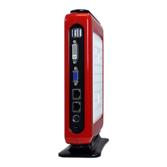
Product Overview I/O panel 2 x USB2.0 port 12V DC input DVI port Power button VGA connector 2 x USB 2.0 port 2 x LAN RJ-45 Port Earphone/headphone jack PS/2 Mouse/Keyboard Port Microphone jack There are two LEDs on each LAN port. Please refer to the table below for the LAN port LED indications. -
Page 8: Vga Pin Description
VGA pin description VGA signal input connector Pin NO. Pin Assignment Pin Description Remark VGA R VGA Red signal VGA G VGA Green signal VGA B VGA Blue signal No connection Ground Ground Ground Ground No connection Ground No connection CRT DDC Data The data of display data channel VGA HS VGA H-Sync signal... -
Page 9: Dvi Pin Description
DVI pin description 17 9 DVI signal input connector Pin NO. Pin Description Pin NO. Pin Description T.M.D.S _ Data 2- Hot plug _ detect T.M.D.S _ Data 2+ T.M.D.S _ Data 0- Ground T.M.D.S _ Data 0+ Ground DDC _ clock DDC _ data Ground Analog _ VSYNC... -
Page 10: Physical Dimensions
Physical dimensions The following diagram depicts the dimensions of the AP-3500. :1.76" : 7.14" : 8.74" : 9.31" : 2.77" : 6.00" Model Number Weight AP-3500 2.77" 7.14" 9.31" 1.76" 6.00" 8.74" 0.91 KG (ACP Enabled) -
Page 11: Installing
Installing This unit can be placed on a shelf or table, or mounted onto the back of a computer screen. Refer to the illustration below to mount the unit onto the back of a computer screen. 1. Locate the four screw holes in the back of the computer screen. Screw holes 2. - Page 12 3. Slide the base bracket to remove it from the unit. Base bracket Slide 4. Push the unit into the mount panel until the panel clicks and locks the unit in place. 5. To uninstall the unit, press the two irons (with springs) simultaneously on both sides to release the unit.
-
Page 13: Connecting To A Display
Connecting to a display No specific tools are required to connect the AP-3500 to a display or monitor. Simply follow these instructions outlined in the diagram below. 1. Connect to a display via DVI cable AP-3500 (ACP Enabled) ARISTA ADM-1815 Display (SOLD SEPERATELY) DVI cable (not supplied) : Signal flow 2. Connect to a display via VGA cable... -
Page 14: Connecting A Keyboard And A Mouse
Connecting a keyboard and a mouse Figure 1 shows how to connect a USB keyboard and mouse and Figure 2 shows how to connect a PS/2 keyboard and mouse. AP-3500 (ACP Enabled) Figure 1 Figure 2 AP-3500 (ACP Enabled) -
Page 15: Connecting To A Network
Connecting to a network • Connect one end of the network cable (not supplied) to the LAN port of your PC, and connect the other end to the broadband modem or router. AP-3500 (ACP Enabled) Modem LAN cable (not supplied) Connecting earphones/headphones or speakers • Connect earphones/headphones or speakers with a 3.5mm audio cable (NOT INCLUDED). -
Page 16: Connecting The Power Adapter
• Connect the round shape plug end of the AC/DC adapter to the DC Power input connector of the AP-3500. Connect the female end of the power cable to the AC power input receptacle on the AC/DC adapter. Then plug the male end of the power cable into an AC outlet. -
Page 17: Using Bios
Using BIOS About the setup utility Award’s BIOS ROM has a built-in Setup program that allows user to modify the basic system configuration. This type of information is stored in battery-backed CMOS RAM so that it retains the Setup information when the power is turned off. The standard configuration A standard configuration has already been set in the Setup Utility. However, we recommend that you read this chapter in case you need to make any changes in the future. This Setup Utility should be used: • when a configuration error is detected and you are prompted to make changes to the Setup Utility • when trying to resolve IRQ conflicts... -
Page 18: Bios Navigation Keys
BIOS navigation keys The BIOS navigation keys are listed below: FUNCTION Exits the current menu Scrolls through the items on a menu +/-/PU/PD Modifies the selected field’s values Saves the current configuration and exits setup Displays a screen that describes all key functions Loads previously saved values to CMOS Loads a minimum configuration for troubleshooting Loads an optimum set of values for peak performance Using BIOS... -
Page 19: Standard Cmos Features
Standard CMOS Features When you choose the Standard CMOS Features option from the Initial Setup Screen menu, the screen shown below is displayed. This standard Setup Menu allows users to configure system components such as date, time, hard disk drive, floppy drive and display. Once a field is highlighted, on-line help information is displayed on the right of the Menu screen. Phoenix-AwardBIOS CMOS Setup Utility Standard CMOS Features Item Help Date (mm:dd:yy) Thu. - Page 20 IDE HDD Auto-Detection Press <Enter> while this item is highlighted to prompt the Setup Utility to autumatically detect and configure an IDE device on the IDE channel. Serial ATA Channel 1/2 (Auto) Leave this item at Auto to enable the system to automatically detect and configure SATA devices on the channel. If it fails to find a device, change the value to Manual and then manually configure the drive by entering the characteristics of the drive in the items described below. Refer to your drive's documentation or look on the drive casing if you need to obtain this information.
-
Page 21: Advanced Bios Features
Advanced BIOS Features This section allows you to configure and improve your system and allows you to set up some system features according to your preference. Phoenix-AwardBIOS CMOS Setup Utility Advanced BIOS Features CPU Feature [Press Enter] Item Help ... - Page 22 CPU Feature (Press Enter) Users please note that this function is only available for Prescotte CPUs. Scroll to this item and press <Enter> to view the following screen: Phoenix-AwardBIOS CMOS Setup Utility CPU Feature Item Help Delay Prior to Thermal [16 Min] Limit CPUID MaxVal [Disabled]...
- Page 23 Hard Disk Boot Priority (Press Enter) Scroll to this item and press <Enter> to view the following screen: Phoenix-AwardBIOS CMOS Setup Utility Hard Disk Boot Priority Item Help 1. Bootable Add-in Cards Menu Level Use < > or < > to select ...
- Page 24 First/Second/Third Boot Device (Hard Disk/CDROM/USB-CDROM) Use these three items to select the priority and order of the devices that your system searches for an operating system at start-up time. Boot Other Device (Enabled) When enabled, the system searches all other possible locations for an operating system if it fails to find one in the devices specified under the First, Second, and Third boot devices.
- Page 25 Full Screen LOGO Show (Enabled) Allows you to determine whether to display the manufacturer's Logo at system startup. Disable it to display normal POST message. Small Logo (EPA) Show (Disabled) This item enables or disables the display of the EPA logo during boot. Press <Esc>...
-
Page 26: Advanced Chipset Features
Advanced Chipset Features Since the features in this section are related to the chipset on the CPU board and are completely optimized, you are not recommended to change the default settings in this setup table unless you are well oriented with the chipset features. Phoenix-AwardBIOS CMOS Setup Utility Advanced Chipset Features DRAM Timing Selectable... - Page 27 SLP_S4# Assertion Width (4 to 5 Sec.) This item selects a minimum assertion width of the SLP_S4# signal. System BIOS Cacheable (Enabled) This item allows the system to be cached in memory for faster execution. Enable this item for better performance. Video BIOS Cacheable (Disabled) The item allows the video BIOS to be cached in memory for faster execution.
- Page 28 On-Chip Frame Buffer Size (8MB) This item will be different as your memory modules. When the memory size is decided, this frame buffer size will also be fixed. The Choices: 8MB (default), 1MB. DVMT Mode (DVMT) This item allows you to select the DVMT operating mode. DVMT/FIXED Memory Size (128MB) When set to Fixed Mode, the graphics driver will reserve a fixed portion of the system memory as graphics memory.
-
Page 29: Integrated Peripherals
Integrated Peripherals These options display items that defines the operation of peripheral components on the system's input/output ports. Phoenix-AwardBIOS CMOS Setup Utility Integrated Peripherals OnChip IDE Device [Press Enter] Item Help Onboard Device [Press Enter] Super IO Device [Press Enter] Menu Level USB Device Setting [Press Enter] F1: General Help +/-/PU/PD: Value F10: Save ESC: Exit... - Page 30 IDE DMA transfer access (Enabled) This item allows you to enabled the transfer access of the IDE DMA. On-Chip Primary PCI IDE (Enabled) The integrated peripheral controller contains an IDE interface with support for two IDE channels. Select Enabled to activate each channel separately. IDE Primary Master/Slave PIO (Auto) Each IDE channel supports a master device and a slave device.
- Page 31 Super IO Device (Press Enter) Scroll to this item and press <Enter> to view the following screen: Phoenix-AwardBIOS CMOS Setup Utility Super IO Device Item Help POWER ON Function [BUTTON ONLY] KB Power ON Passward Enter Hot Key Power ON Ctrl-F1 ...
- Page 32 Parallel Port Mode (SPP) This option enables you to set the data transfer protocol for your parallel port. Options: SPP (Standard Parallel Port), EPP (Enhanced Parallel Port), ECP (Extended Capabilities Port), and ECP+EPP. EPP Mode Select (EPP 1.7) Use this item to select the EPP Mode Type: EPP1.7 or EPP1.9. ECP Mode Use DMA (3) When the onboard parallel port is set to ECP mode, the parallel port can use DMA3 or DMA1.
-
Page 33: Usb Device Setting
USB Device Setting Scroll to this item and press <Enter> to view the following screen: Phoenix-AwardBIOS CMOS Setup Utility USB Device Setting Item Help USB 1.0 Controller [Enabled] USB 2.0 Controller [Enabled] USB Operation Mode [High Speed] Menu Level USB Keyboard Function [Enabled] USB Mouse Function... -
Page 34: Power Management Setup
Power Management Setup The Power Management Setup allows you to save energy of your system effectively. It will shut down the hard disk and turn OFF video display after a period of inactivity. Phoenix-AwardBIOS CMOS Setup Utility Power Management Setup Item Help ACPI Function [Enabled]... - Page 35 Video off Method (DPMS) This item defines how the video is powered down to save power. This item is set to DPMS (Display Power Management Software) by default. Video off In Suspend (Yes) This option defines if the video is powered down when the system is put into suspend mode. Suspend Type (Stop Grant) If this item is set to the default Stop Grant, the CPU will go into Idle Mode during power saving mode. MODEM Use IRQ (3) If you want an incoming call on a modem to automatically resume the system from a power-saving mode, use this item to specify the interrupt request line (IRQ) that is used by the modem.
-
Page 36: Reload Global Timer Events
USB KB WakeUp From S3(S4) (Disabled) This item allows you to enable/disable the USB device wakeup function from S3/S4 mode. Resume by Alarm (Disabled) When set to Enabled, additional fields become available and you can set the date (day of the month), hour, minute and second to turn on your system. -
Page 37: Pnp/Pci Configurations
PnP/PCI Configurations These options configure how PnP (Plug and Play) and PCI expansion cards operate in your system. Both the the ISA and PCI buses on the motherboard use system IRQs (Interrup ReQuests) and DMAs (Direct Memory Access). You must set up the IRQ and DMA assignments correctly through the PnP/PCI Configurations Setup utility for the motherboard to work properly. Selecting PnP/PCI Configurations on the main program screen to display this menu: Phoenix-AwardBIOS CMOS Setup Utility PnP/PCI Configurations Item Help Init Display First... -
Page 38: Pc Health Status
PCI/VGA Palette Snoop (Disabled) Some non-standard VGA display cards may not show colors properly. This feild allows you to set whether MPEG ISA/VESA VGA Cards can work with PCI/VGA or not. When enabled, a PCI/VGA can work with a MPEG ISA/VESA VGA Card. When disabled, a PCI/VGA cannot work with a MPEG ISA/VESA VGA Card. -
Page 39: Load Fail-Safe Defaults Option
Load Fail-Safe Defaults Option This option opens a dialog box that lets you install fail-safe defaults for all appropriate items in the Setup Utility: Press <Y> and the <Enter> to install the defaults. Press <N> and then <Enter> to not install the defaults. -
Page 40: Save & Exit Setup
Save & Exit Setup Highlight this item and press <Enter> to save the changes that you have made in the Setup Utility and exit the Setup Utility. When the Save and Exit dialog box appears, press <Y> to save and exit, or press <N>... -
Page 41: Specifications
Specifications System Intel Atom N 270 1.6 GHz Chipset 945GSE + ICH7M Memory Up to 2GB DDR2-667 Resolution Up to 1920 x 1080 Video Interface VGA, DVI Storage Option Optional SATA DOM Compact Flash Keyboard/Mouse USB/PS2 Audio Line Out, MIC Watchdog Timer Expansion Slot Mini PCle... -
Page 42: Maintenance
(invoice date), at its option either repair your product with new or refurbished parts, or replace it with new or a refurbished product. • The decision to repair or replace will be made by Arista Corp. During the “Labor” Limited Warranty period there will be no charge for labor. During the “Parts” Limited Warranty period, there will be no charge for parts. -
Page 43: Technical Support
• Products will not be accepted by Arista Corp. RMA department for return if not accompanied by a valid RMA number, which must be clearly marked on the outside of the package. -
Page 44: Rma Credit Policy
• In cases of transportation damage, customer is responsible for filing any and all claims with the shipping carrier. • To avoid any potential risk that an RMA product is lost or damaged while in transit to Arista, it is recommended that the customer insures and declares the full value of the RMA product since the customer is 100% responsible for the RMA product while in transit to Arista. -
Page 45: Rma Shipping Instruction
7. RMA Shipping Instruction Product Non-Acceptance • Products will not be accepted by Arista Corp. if not accompanied by a valid RMA number, which must be clearly marked on the outside of the package. • Any products refused by Arista will incur the fees and/or charges applied by the shipping carrier, and shall be the sole liability of the original shipper. -
Page 46: Arista's Limited Liability
Arista Corporation Limited Liability policies. • Arista Corporation is not liable for damages or reimbursement for lost time, lost revenue, cost of having someone remove or re-install an installed unit if applicable, or travel to and from the service providers. - Page 48 Talk to us. We listen. Arista Corporation 40675 Encyclopedia Circle, Fremont, CA 94538 U.S.A. Tel: (510) 226-1800 Fax: (510) 226-1890 http://www.goarista.com...
Need help?
Do you have a question about the AP-3500 and is the answer not in the manual?
Questions and answers