Baxi Bermuda RG 3 Installation And Servicing Instructions
Fireside gas central heating unit
Hide thumbs
Also See for Bermuda RG 3:
- User's operating (8 pages) ,
- User operating instructions manual (8 pages)

Related Manuals for Baxi Bermuda RG 3


Summary of Contents for Baxi Bermuda RG 3
- Page 1 Please leave these instructions with the user Baxi Bermuda RG 3 Fireside Gas Central Heating Unit Installation and Servicing Instructions...
- Page 2 Everyone who works at Baxi has a commitment to quality because we know that satisfied customers mean continued success. We hope you get a satisfactory service from Baxi. If not, please let us know. For use in GB / IE only.
-
Page 3: Table Of Contents
CONTENTS Introduction PAGE Technical Data PAGE Site Requirements PAGE Fireplace Opening Hearth Mounting Wall Fixing Installation 8-15 PAGE Initial Preparation Electrical Connections Gas Supply Fitting the Fire Commissioning the Fire 16-18 PAGE Spillage Detection Fitting the Outer Case PAGE Annual Servicing 20-23 PAGE Cleaning the Burner and Injectors... - Page 4 Information Codes of Practice, most recent version should be used Safe Installation In GB the following Codes of Practice apply: Standard Scope The appliance is suitable only for installation in GB and IE BS 6891 Gas Installation. and should be installed in accordance with the rules in force. BS 5546 Installation of hot water supplies for domestic purposes.
-
Page 5: Introduction
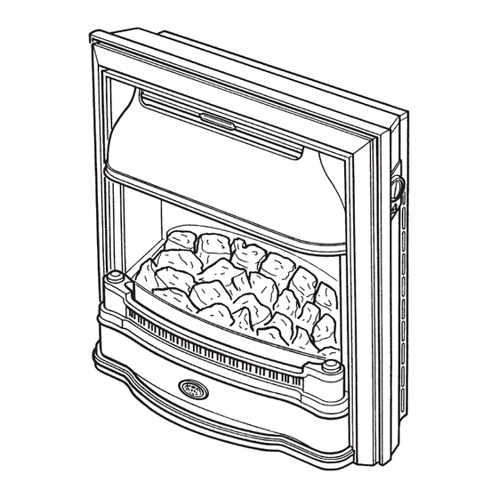
INTRODUCTION Description The Baxi Bermuda RG3 (G.C. N 37 077 64) is a combined gas fired central heating boiler and gas fire unit, designed for installation in a living room. The boiler and fire unit is designed to be used on Natural Gas only. -
Page 6: Technical Data
TECHNICAL DATA Bermuda RG3 (Natural Gas) Heat Input (Gross) High Med-High Gas Connection The gas supply is 76mm provided from the 5.52 4.88 service cock on the boiler unit. Btu/h 18,834 16,637 Electricity Supply 230V~50Hz Heat Input (Gross) External fuse - 3Amp Appliance Rating - 30 watt 3.72 2.00... -
Page 7: Site Requirements
SITE REQUIREMENTS 406mm Min Fireplace Opening 584mm Max The principal site requirements are determined by the boiler unit, but the following details are essential for the correct installation of the fire unit: Fireplace Opening 560mm Fireplace Opening: Height: 560mm (22in) Width: 406mm (16in) min 584mm (23in) max NOTE: The wall behind the fire must be non-... -
Page 8: Installation
INSTALLATION Pilot / A.S.D. Initial Preparation Plug Assembly Unpack the fire unit. Electrical Connections Electrode Micro-Switch Terminal Strip Spark Generator Light Switch Resistor Bulb Bulb br - Brown b - Blue w - White r - Red g/y - Green & Yellow LAMP BOX THIS APPLIANCE MUST BE EARTHED NOTE: The method of connection to the electricity... - Page 9 Manual Control Models If the fire supply cable has not been fitted when wiring the boiler proceed as follows:- CONNECTING ELECTRICAL SUPPLY TO THE BOILER Connect the wiring to the boiler as follows:- Extract the screw that fixes the boiler controls connection plug to the socket on the boiler base tray and disconnect the plug.
- Page 10 CONNECTING THE FIRE ELECTRICAL SUPPLY CABLE TO THE BOILER If the boiler electrical connections have already been made, ensure that the electrical supply to the boiler is isolated. The fire should always be electrically connected as described below and must not be provided with an electrical connection that is independent from the boiler.
- Page 11 Electronic Controls Models If the boiler electrical connections have already been made, ensure that the electrical supply to the boiler is Controls Heat isolated. The fire should always Shield be electrically connected as described below and must not be provided with an electrical connection that is independent from the boiler.
- Page 12 Electronic Controls Model (51/5 only) 3 Pin Electrical Plug 4 Pin Electrical Inlet Socket Remove the controls heat shield from its retaining clips. Isolate the electrical supply to the boiler, including the permanent live. Remove the electrical inlet socket from the PCB at the rear left hand side of the control box.
- Page 13 Gas Supply The gas installation should be in accordance with relevant standards. In GB this is BS 6891. In IE this is I.S. 813 “ Domestic Gas Installations”. The gas supply to the fire unit is provided from the service cock on the boiler using the fire supply pipe contained in the kit.
- Page 14 Boiler Canopy Fitting the Fire HEARTH FIXING Ensure that the space between the flue liner and the chimney has been sealed, as described in the flues section of the Boiler Instruction. Controls Heat Shield The backing plate that will be used to secure the fire to the wall is already fastened to the fire in readiness for marking out the screw fixing holes.
- Page 15 WALL FIXING Ensure that the space between the flue liner and the chimney has been sealed, as described in the flues section of the Boiler Instruction. On electronic control boilers it will be necessary to remove the inlet plug from the controls. Take the fire support plate from the fire Fire Support unit packaging and loosely attach it to the...
-
Page 16: Commissioning The Fire
COMMISSIONING THE FIRE Three clips across the top of the glass frame secure it in position. When the clips are released, the glass frame assembly will lean outwards to rest on its bottom location positions, from which it can be lifted clear of the fire. - Page 17 Switch on the bulbs. If the bulbs light, then switch off and proceed. If they do not light isolate the electricity supply and perform preliminary electrical system checks before proceeding, ie earth continuity, polarity, resistance to earth etc. Release the pressure test point sealing screw from the gas control tap and connect a pressure gauge in position.
- Page 18 CHECKING FOR SPILLAGE CAUTION - Whilst checking for spillage care must be taken to avoid touching hot panels. Ensure that all doors and windows are closed. IMPORTANT NOTE: If there is a ceiling or extractor fan in the room or adjoining room then the spillage test must be performed with the fan Access for turned on and any interconnecting doors between...
-
Page 19: Fitting The Outer Case
FITTING THE OUTER CASE Centre Locating Ledge First turn off the fire and allow it to cool down. at Rear of Top Panel There are 3 outer case components which are to be fitted as follows:- Fire Top Panel Locating Lip FIRE TOP PANEL Hold the panel on either side with the screw fixing holes towards the front. -
Page 20: Annual Servicing
ANNUAL SERVICING For reasons of safety and economy it is important to service both the fire and boiler unit annually. Before servicing please read the Important Information section on page 5. IMPORTANT: It is possible that some soot may be deposited on the coals after use. - Page 21 Remove the Fire chassis as follows :- The lamp box, which is clipped at the top and hinged Rotate Lamp Box at the bottom is rotated forward to expose the boiler Forward Using controls. Use the handles provided. The Handles Handle Electricity is supplied to the fire by means of a 3 pin socket from the boiler.
- Page 22 Check that the spark gap between the electrode and thermocouple is between 2.5 and 4mm. Some appliances may experience nuisance shut down of the pilot. A pilot shield kit (Baxi Part No. 237319) is available to prevent this.
- Page 23 Boiler Canopy REPLACING THE FIRE Controls Heat Shield Fire Flue Spigot Once the boiler has been serviced, the fire can be replaced. Down-Draught Diverter Locate the fire flue spigot into the boiler canopy and whilst ensuring that the down-draught diverter on the fire unit passes over the boiler controls heat shield, push the fire back against the backing plate.
-
Page 24: Changing Components
CHANGING COMPONENTS CAUTION :- After replacing any gas carrying components always check for gas soundness. (BS 6891). Before changing any components please read the Important Information section on page 5. INITIAL PREPARATION Remove the Outer Case Components as follows :- Ensure the fire is cold. - Page 25 LIGHT BULBS Your attention is drawn to the safety notice found on the lamp box. With the electricity supply to the fire isolated, the light bulbs can be changed as necessary. They should only be replaced with 15 Watt pygmy bulbs. GLASS FRAME ASSEMBLY Ensure that the glass panel is cold.
- Page 26 BURNER AND INJECTORS Remove the glass frame assembly and coalbed. Glass Frame Release the compression nuts that connect the gas feed pipes to the injectors on the burner. The coalbed location pins also secure the burner in position. Unscrew and remove the pins. Manoeuvre the burner clear of the fire, taking care not to damage the pilot assembly.
-
Page 27: Electro-Magnetic Unit
PILOT ASSEMBLY Remove the glass frame assembly and coalbed. Glass Frame Grip the pilot assembly and loosen the compression nut that connects the pilot gas supply pipe to it. Remove the two screws that retain the pilot assembly. Remove the pilot gas supply pipe and Pilot Assembly other associated... -
Page 28: Light Switch And Micro-Switch
LIGHT SWITCH AND MICRO SWITCH For either of these operations the bezel is first removed. TO REMOVE THE BEZEL :- Ensure that the electricity supply to the fire unit is isolated. Remove the control knob by pulling it from the spindle. Retaining Barbs Undo the screw securing the bezel. -
Page 29: Gas Control Tap And Pilot Filter
GAS CONTROL TAP AND PILOT FILTER Fire Top Panel Ensure that the electricity and gas supply to the fire unit is isolated. Fire Top Panel Remove the two fixing screws that secure the fire top panel to the chassis and lift the panel at the front to release it from the fire. -
Page 30: Electrode Lead, Resistor And Spark Generator
ELECTRODE LEAD,RESISTOR OR SPARK GENERATOR To replace any of these components it is necessary to gain access to the inside of the lamp box. Rotate Lamp Box Forward Using The lamp box, which is clipped at the top and The Handles hinged at the bottom is rotated forward to lay flat. - Page 31 SHORT PARTS LIST G.C. Description Manufacturers Part No. 156 232 Glass and Frame Assy 233864 156 233 Knob Fire Control 233466 156 063 Rope Seal 226876 156 301 Pilot Assembly 234099 E01-562 Kit - Tap - Gas Control 239411 105a 384 248 Electro Magnetic Unit 082462...
-
Page 32: Fault Finding
? Rectify flue 2.5 to 4mm Change microswitch The thermocouple cannot be changed as an individual component.The complete assembly must be replaced in the event of one or other component failure(s). Spark Gap Only use a Genuine Baxi Spare Part. - Page 33 Does both bulbs Fire satisfactory the fire remain light ? alight ? Open gas cocks gas cocks fully Does one open ? Replace faulty bulb bulb light? meter pressure Contact the Gas Supplier correct ? Are bulbs Switch on bulbs switched on ? Pipework supply pressure...
- Page 34 37 075 06A Valve Heat Shield The kit supplied with Renewal appliances provides all the necessary components to fit a Baxi Bermuda RG3 Controls Heat Shield Renewal firefront to the following Bermuda Boilers. The Renewal Fires may be used with the following...
- Page 35 If the fire is wall mounted remove and discard the existing support frame. (Bermuda 401 only) Retain the two support brackets. These will be needed in wall mounting the renewal fire. If the fire is hearth mounted ensure that the base of the builders opening and the front hearth are at the same level.
- Page 36 B A X I P O T T E R T O N Brownedge Road Bamber Bridge Preston Lancashire PR5 6SN After Sales Service 08706 096 096 Technical Enquiries 08706 049 049 Comp No 237641 - Iss 6 - 1/03 www.baxi.co.uk...
Need help?
Do you have a question about the Bermuda RG 3 and is the answer not in the manual?
Questions and answers