Table of Contents
Advertisement
Pulse 2.200 LS
Features
The P2.200 LS amplifier contains two identical independent amplifier modules. Each has one Main and one
Aux. input. Routing logic allows the Main and Aux. to mix; this allows the monitoring tone to pass at all times
and the monitoring system to operate. If the PTT is operated, the Main input overrides the Aux.
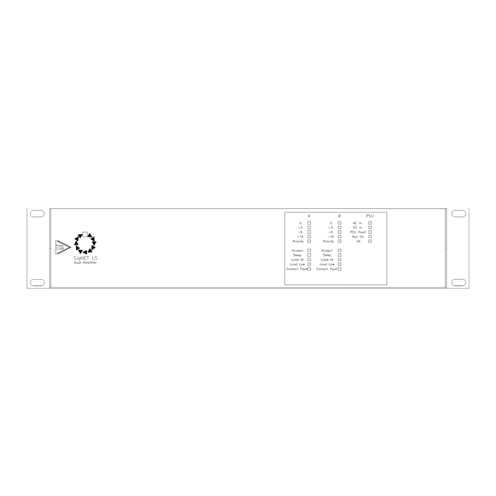
Each module's status is displayed on the front panel along with an output level bar graph and status
indicators. All sections of the amplifier and charger are constantly monitored for faults or abnormal operation:
1
The load monitoring checks the power absorbed by the loudspeaker load at 22 kHz and compares this
with the threshold and window levels set at installation. If the power drawn deviates outside the window a
fault is indicated on the front and rear of the unit and signalled to other equipment via the relevant fault
outputs.
2
If the impedance monitoring tone is not being received by the amplifier, both the Load Hi and Load Low
front LEDs light and the rear Tone Fail light shows.
3
Should either leg of the loudspeaker wiring short to system earth this will also light the Load Hi and Load
Low LEDs on the front panel, along with the Earth Fault LED on the rear.
4
Mains power status is also monitored, along with the internal fuses, to give a complete picture of the state
of the amplifier.
The load monitoring system also provides an output to drive a 'hot swap' automatic amplifier replacement
system, via the HSP port, on failure of the amplifier only. Should a load fail short or open circuit but the
amplifier is still OK, the hot swap output will not operate. This means that any loudspeakers that can be
driven will operate and leaves the hot swap amplifier available for use on another potential failure.
The output from each module is presented on a three-way socket and is fully floating. The standard output
voltages are 50V and 100V, allowing two modules to be connected in series to give 400W at 100V line.
The power supply has a 24 Vd.c. battery input and an onboard battery charger.
Technical Description
Amplifier Modules
The Aux. and Main line level inputs are de-balanced and pass via level controllers and an analogue switch
into a summing amplifier where they are mixed. If the contact input is asserted (470 ohms to ground) a logic
circuit disconnects the aux. input.
The protect circuit disconnects the output transformer when the voltage rails fall below 22 Volts, exceed 36
Volts, or when a d.c. offset is present on the output rails. The signal then passes through to the output stage,
which is a feed-forward current-mode bridge circuit and the output level meter monitors the level at this stage.
The output current is passed through the primary of the output transformer and through a low value output-
sensing resistor. The output of the transformer is tapped at 50 and 100 Volts. If the 50 Volt taps are
connected in series the unit provides a single 400 Watt output at 100 V line.
Power Supply
A large capacitor reservoir provides a very smooth output, even under large current surges. Two separate
internal 10 Amp fused outputs connect to the two amplifier modules.
A separate low-current feed passes via the sleep enable selector link into the sleep timer section. Another
feed passes, via the Aux. on LED (this shows that the Aux. power is available on the rear connector) through
a 3 Amp fuse to the Aux. power connector. With mains voltage operation this unregulated output is at
approximately 32 Vd.c. When mains has failed, this output is connected to the battery and therefore operates
at battery voltage level.
A 27.6 Volt regulator is also taken off this line and used to charge external batteries via a 20 Amp fuse.
PSU and amplifier faults are returned into the monitoring circuit from both amplifiers, slugged to prevent false
faults being reported externally, and passed to the open collector fault outputs on the SIP port. A fourth open
collector output is normally set as OK (normally closed) and opens when any fault occurs.
Operation Instruction Manual
Dual 200W 100V line Amplifier with Monitoring
Page 1 of 12 DocNo.DCP0001326 DSM 06/01/05 rev7
Advertisement
Table of Contents

Related Manuals for Signet Pulse 2.200 LS


Summary of Contents for Signet Pulse 2.200 LS
-
Page 1: Technical Description
Operation Instruction Manual Pulse 2.200 LS Dual 200W 100V line Amplifier with Monitoring Features The P2.200 LS amplifier contains two identical independent amplifier modules. Each has one Main and one Aux. input. Routing logic allows the Main and Aux. to mix; this allows the monitoring tone to pass at all times and the monitoring system to operate. -
Page 2: Block Diagrams
Block Diagrams Front panel indicators P2.200LS OVERALL BLOCK DIAGRAM ISSUE 1. HOT SWAP PORT A MODULE A PORT MODULE A 230VAC 50/60Hz PSU/ DISPLAY CHARGER FAULTS AUX 27.6V MODULE B 24V SEALED LEAD-ACID BATTERY MODULE B HOT SWAP PORT B SHOWS THE OVERALL CONFIGURATION OF PSU AND AMP MODULES PLUS DISPLAY P2.200LS PSU MODULE BLOCK DIAGRAM ISSUE 1. - Page 3 Each amplifier’s current status is displayed on the front panel, along with output bar graphs for each channel, and the access status. All indicators are in accordance with BS 5839: Part 4: 1988. Each amplifier module has a separate indication on the front panel for the following states: Name Function / Description Output level...
-
Page 4: Rear Panel Controls & Features
Rear panel controls & features Name Function/Description Name Function/Description Switch Switches mains power AC Input 6A IEC 3 pin connector (Fuse: 5A 250V 20mm HBC) Battery Rear of CliffCon 4 Hot Swap Input PC/P Port Pin 1- : GND Pin 1+ : +24V DC @ 20A Aux. -
Page 5: Installation
150 Amps! It is therefore essential that mains power is only derived from an automatic soft start device such as SigNET’s SOFT4. - Page 6 DC power operation and Battery Calculation The P2.200LS is designed to operate with two 12 Volt VRLA batteries connected in series. BS5839-8 1988 requires that batteries must be capable of operating the system according to the project requirements (normally 24 Hours in a quiescent current state plus 30 minutes in full alarm). It also requires that batteries be sized so as to provide 25% overcapacity to allow for loss of capacity over time.
-
Page 7: Fault Monitoring
Fault Monitoring PTT monitoring The contact input (PTT in) is monitored by a resistive potential divider as shown below; The current drawn by the 6K8Ω resistor (in the 27V6DC previously connected unit) proves that the PTT line is intact. Open and short circuit faults are separately detected and operation of the PTT is detected by the change in voltage level at the PTT Input... - Page 8 20 Khz monitoring tone). End of line units (supplied with the amplifier) must also be fitted. Connecting the P2.200 to a SigNET SS2n (Network station), including battery backup. 1. SS2n feeding both amplifier modules 2. SS2n feeding only one amplifier module Connecting the P2.200 to an Integrity Mainframe.
-
Page 9: Output Connections
Once an amplifier is installed and powered up, it is necessary to adjust or verify the following settings: 1. Ensure that an audio lead from a SigNET routing matrix is connected to both Main Inputs a. 2. Check that the monitoring tone is not disabled (the tone fail (TF) indicator is not lit). -
Page 10: Internal Adjustments
SIP connector. By default these are connected via wire links to pins 1 to 4 this used by SigNET to designate a node A amplifier. With the header-reversed pins 5 to 8 are connected. This configuration is used by SigNET to designate a node B amplifier. -
Page 11: Specification
Charging voltage 27.6 V DC Charging current Monitoring Short circuit and battery high impedance Aux. Supply SIP Port User assignable faults for the SigNET network Monitoring Detection frequency 22.05kHz Detection type Window comparator system Window 5% to 20% user adjustable... - Page 12 PSU pcb showing internal fuse locations Fuses are commonly available automotive blade types SPECIFICATIONS ARE SUBJECT TO CHANGE WITHOUT PRIOR NOTICE SigNET (AC) Limited 6 Tower Road Glover Estate, Washington, Tyne & Wear, NE37 2SH Tel: +44 (0)191 417 4551 Fax: +44 (0)191 417 0634 info@signet-ac.com...
Need help?
Do you have a question about the Pulse 2.200 LS and is the answer not in the manual?
Questions and answers