Bolens 600 Series Service Manual
Box frame
Hide thumbs
Also See for 600 Series:
- Service and repair manual (101 pages) ,
- Service and repair manual (74 pages)
Advertisement
(These procedures are appropriate for box frame tractors produced after November 2002)
IMPORTANT: READ SAFETY RULES AND INSTRUCTIONS CAREFULLY
This Service Manual is not a substitute for the Operator's Manual. You must read, understand
and follow all of the directions in this manual as well as the Operator's Manual before working
on this power equipment.
TROY-BILT LLC, P.O. BOX 361131, CLEVELAND, OH 44136-0019
PRINTED IN USA
Service Manual
600 Series Box Frame
FORM NO. 769-00947
(10/2003)
Advertisement
Table of Contents

Related Manuals for Bolens 600 Series


Summary of Contents for Bolens 600 Series
- Page 1 Service Manual 600 Series Box Frame Steering Shaft and Segment Gear Servicing (These procedures are appropriate for box frame tractors produced after November 2002) IMPORTANT: READ SAFETY RULES AND INSTRUCTIONS CAREFULLY This Service Manual is not a substitute for the Operator’s Manual. You must read, understand and follow all of the directions in this manual as well as the Operator’s Manual before working...
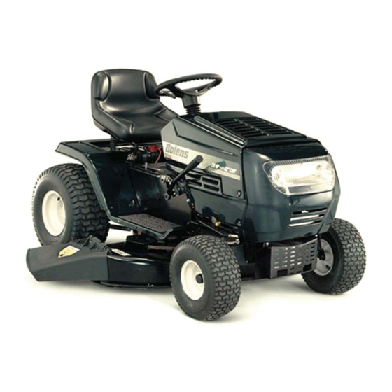
- Page 3 Steering Shaft and Segment Gear Servicing Steering Shaft and Segment Gear Servicing 600 Series Box Frame Lawn Tractors 600 SERIES BOX FRAME LAWN TRACTORS 1.1. Using a screwdriver, pry the steering wheel cap from the center of the steering wheel. See Fig- BOLENS RIDER SHOWN ure 1.
- Page 4 Steering Shaft and Segment Gear Servicing 1.4. Using an impact gun with a large Phillips head 1.7. Using a 3/8” socket remove the four (two on socket, remove the machine screw and cap each side) self-tapping screws securing the rear securing the steering shaft to the frame.
- Page 5 Steering Shaft and Segment Gear Servicing 1.9. Remove the wiring connector attached to the 1.11. Lift and pivot the dash panel to the left while ignition switch. See Figure 7. removing the steering shaft from the hole in the frame by the steering segment gear. See Figure Figure 7 Figure 9 1.10.
- Page 6 Steering Shaft and Segment Gear Servicing 1.13. Inspect the steering shaft, pressed-on gear, STEERING SEGMENT GEAR REMOVAL washer, hex flange bearing, cap and machine NOTE: For ease of repair refer to DECK screw for wear or damage. See Figure 10. REMOVAL SECTION.
- Page 7 Steering Shaft and Segment Gear Servicing 2.3. Using a 5/8” box end wrench on the upper side 2.5. Remove the segment gear, steering drag link, of the shoulder screw and an air gun with a ½” and ball joint as one assembly from the rider and socket on the flange lock nut, remove the flange inspect for any wear or damage.
Need help?
Do you have a question about the 600 Series and is the answer not in the manual?
Questions and answers