Table of Contents
Advertisement
Multi-Function printer
KX-MB1520FX7
Model No.
KX-MB1520FX8
KX-MB1520FXW
KX-MB1530FX7
KX-MB1530FXW
(KX-MB1520FX7/KX-MB1520FX8/KX-MB1530FX7: for
Algeria, Jordan, Oman)
(KX-MB1520FX7/KX-MB1530FXW: for Eastern Europe)
© Panasonic System Networks Co., Ltd. 2012
Unauthorized copying and distribution is a violation
of law.
ORDER NO.KMF1108383CE
Advertisement
Table of Contents
Troubleshooting

Related Manuals for Panasonic KX-MB1520FX7


Summary of Contents for Panasonic KX-MB1520FX7
- Page 1 ORDER NO.KMF1108383CE Multi-Function printer KX-MB1520FX7 Model No. KX-MB1520FX8 KX-MB1520FXW KX-MB1530FX7 KX-MB1530FXW (KX-MB1520FX7/KX-MB1520FX8/KX-MB1530FX7: for Algeria, Jordan, Oman) (KX-MB1520FX7/KX-MB1530FXW: for Eastern Europe) © Panasonic System Networks Co., Ltd. 2012 Unauthorized copying and distribution is a violation of law.
-
Page 2: Table Of Contents
KX-MB1520FX7/KX-MB1520FX8/KX-MB1520FXW/KX-MB1530FX7/KX-MB1530FXW TABLE OF CONTENTS PAGE PAGE 1 Safety Precautions -----------------------------------------------6 6.9.3. Flat torque 1-2 phase excitation (half step) 1.1. For Service Technicians ----------------------------------6 ----------------------------------------------------------- 48 1.2. AC Caution---------------------------------------------------6 6.9.4. W 1-2 phase excitation (Quarter step) -------- 49 1.3. Personal Safety Precautions ----------------------------7 6.10. - Page 3 KX-MB1520FX7/KX-MB1520FX8/KX-MB1520FXW/KX-MB1530FX7/KX-MB1530FXW 8.2. Connections------------------------------------------------94 12.5. Document jams (Automatic document feeder) 9 Operating Instructions-----------------------------------------96 (KX-MB1530 only) ------------------------------------- 206 9.1. Your Logo -------------------------------------------------96 13 Service Fixture & Tools ------------------------------------- 208 9.2. Character entry -------------------------------------------97 14 Disassembly and Assembly Instructions------------- 209 9.2.1. To Select Characters Using [] or []---------------97 14.1.
- Page 4 KX-MB1520FX7/KX-MB1520FX8/KX-MB1520FXW/KX-MB1530FX7/KX-MB1530FXW 15.4.2. Operation Board ----------------------------------- 250 17.6.1. Low Voltage Power Supply Board: 15.4.3. Inter-lock Board ------------------------------------ 250 Component View----------------------------------- 293 15.4.4. Gear Board------------------------------------------ 250 17.6.2. Low Voltage Power Supply Board: Bottom 15.4.5. Toner Sensor Board ------------------------------ 250 View --------------------------------------------------- 293 15.4.6.
- Page 5 KX-MB1520FX7/KX-MB1520FX8/KX-MB1520FXW/KX-MB1530FX7/KX-MB1530FXW 19.2.5. ADF Sensor Board -------------------------------- 394...
-
Page 6: Safety Precautions
KX-MB1520FX7/KX-MB1520FX8/KX-MB1520FXW/KX-MB1530FX7/KX-MB1530FXW 1 Safety Precautions 1. Before servicing, unplug the AC power cord to prevent an electric shock. 2. When replacing parts, use only the manufacturer's recommended components. 3. Check the condition of the power cord. Replace if wear or damage is evident. -
Page 7: Personal Safety Precautions
KX-MB1520FX7/KX-MB1520FX8/KX-MB1520FXW/KX-MB1530FX7/KX-MB1530FXW 1.3. Personal Safety Precautions 1.3.1. Moving Sections of the Unit Be careful not to let your hair, clothes, fingers, accessories, etc., become caught in any moving sections of the unit. The moving sections of the unit are the rollers and a gear. There is a separation roller and a document feed roller which are rotated by the document feed motor. -
Page 8: Warning
KX-MB1520FX7/KX-MB1520FX8/KX-MB1520FXW/KX-MB1530FX7/KX-MB1530FXW 2 Warning 2.1. About Lead Free Solder (PbF: Pb free) Note: In the information below, Pb, the symbol for lead in the periodic table of elements, will refer to standard solder or solder that con- tains lead. We will use PbF solder when discussing the lead free solder used in our manufacturing process which is made from Tin, (Sn), Silver, (Ag), and Copper, (Cu). -
Page 9: Discarding Of P. C. Board
KX-MB1520FX7/KX-MB1520FX8/KX-MB1520FXW/KX-MB1530FX7/KX-MB1530FXW 2.2. Discarding of P. C. Board When discarding P. C. Board, delete all personal information such as telephone directory and caller list or scrap P. C. Board. 2.3. Insulation Resistance Test 1. Unplug the power cord and short the two prongs of the plug with a jumper wire. -
Page 10: Note For Repairing
KX-MB1520FX7/KX-MB1520FX8/KX-MB1520FXW/KX-MB1530FX7/KX-MB1530FXW 2.6. Note for Repairing Caution Please inform users of the danger of data being lost at the time of repair. Data will be lost in the following situations. 1. When replacing the ROM ass'y. 2. When replacing the Main board ass'y. -
Page 11: Specifications
KX-MB1520FX7/KX-MB1520FX8/KX-MB1520FXW/KX-MB1530FX7/KX-MB1530FXW 3 Specifications Applicable Lines: Public Switched Telephone Network Document Size: Max. 216 mm in width, Max. 297 mm in length Automatic document feeder (KX-MB1530): Max. 216 mm in width, Max. 356 mm in length Effective Scanning Width: 208 mm... -
Page 12: General/Introduction
KX-MB1520FX7/KX-MB1520FX8/KX-MB1520FXW/KX-MB1530FX7/KX-MB1530FXW 4 General/Introduction 4.1. Optional Accessories Model No. Description Specifications KX-FAT410X 1 toner cartridge Replacement toner cartridge (high capacity) KX-FAT390X 1 toner cartridge Replacement toner cartridge (high capacity) Prints about 2,500 pages at ISO/IEC 19752 standard page. Prints about 1,500 pages at ISO/IEC 19752 standard page. -
Page 13: Features
KX-MB1520FX7/KX-MB1520FX8/KX-MB1520FXW/KX-MB1530FX7/KX-MB1530FXW 5 Features 5.1. General Features General LCD (Liquid Crystal Display) readout 150-sheet paper capacity (64 g/m ~ 75 g/m Flat-Bed Multifunction Laser Fax Large Memory... Performed by DRAM Letter/A4/Legal, G3 compatible Approx. 150 pages of memory transmission Automatic Document feeder (15 sheets) (KX-MB1530 ONLY) Approx. -
Page 14: Technical Descriptions
KX-MB1520FX7/KX-MB1520FX8/KX-MB1520FXW/KX-MB1530FX7/KX-MB1530FXW 6 Technical Descriptions 6.1. Connection Diagram KX-MB1530 ONLY DOCU SENSOR SENSOR IC55 IC54 OPERATION PANEL BOARD CN60 DC FAN MOTOR CN509 CN205 CN701 CN700 CN511 CN506 Speaker MOTOR CN100 CN100 NAME NAME NAME NAME NAME NAME NAME NAME E(G) / A2... -
Page 15: General Block Diagram
KX-MB1520FX7/KX-MB1520FX8/KX-MB1520FXW/KX-MB1530FX7/KX-MB1530FXW 6.2. General Block Diagram MAIN UNIT SOC (IC300) This custom IC is used for general MFP operations. ARM9 operating at 250MHz. SDRAM Controller Controls SDRAM Memory. USB Controller with PHY Apply to USB2.0 HS Scanner I/F Controls the CIS and AFE, and process the scan images. - Page 16 KX-MB1520FX7/KX-MB1520FX8/KX-MB1520FXW/KX-MB1530FX7/KX-MB1530FXW...
-
Page 17: Main Board Section
KX-MB1520FX7/KX-MB1520FX8/KX-MB1520FXW/KX-MB1530FX7/KX-MB1530FXW 6.3. Main Board Section 6.3.1. Data Flow [FAX Tx] 1. An analog image data is output from CIS unit to IC503. IC503 decode the analog data to digital data, and output to IC300. Scanner I/F in IC300 process image data and store it in IC400 through SDRAM I/F. - Page 18 KX-MB1520FX7/KX-MB1520FX8/KX-MB1520FXW/KX-MB1530FX7/KX-MB1530FXW [PC Scan] 1. An analog image data is output from CIS unit to IC503. IC503 decode the analog data to digital data, and output to IC300. Scanner I/F in IC300 process image data and store it in IC400 through SDRAM I/F.
- Page 19 KX-MB1520FX7/KX-MB1520FX8/KX-MB1520FXW/KX-MB1530FX7/KX-MB1530FXW [Copy] 1. An analog image data is output from CIS unit to IC503. IC503 decode the analog data to digital data, and output to IC300. Scanner I/F in IC300 process image data and store it in IC400 through SDRAM I/F.
- Page 20 KX-MB1520FX7/KX-MB1520FX8/KX-MB1520FXW/KX-MB1530FX7/KX-MB1530FXW Description of Pin Distribution (IC300) SOC (System On Chip) PIN NO. PinName POWER SUPPLY VOLTAGE EXPLANATION LEDONB 3.3V SCANNER INTERFACE NCCDON 3.3V SCANNER INTERFACE AFEMCLK 3.3V SCANNER INTERFACE NCCDCP 3.3V NOT USED CCDCLK 3.3V NOT USED PIO29 3.3V OPERATION PANEL INTERFACE PIO57 3.3V...
- Page 21 KX-MB1520FX7/KX-MB1520FX8/KX-MB1520FXW/KX-MB1530FX7/KX-MB1530FXW PIN NO. PinName POWER SUPPLY VOLTAGE EXPLANATION AC26 BSPCLK 3.3V NCU INTERFACE AD01 SDMD14 3.3V SDRAM DATA BUS 14 AD02 SDMD15 3.3V SDRAM DATA BUS 15 AD03 AD04 NBATRST 3.3V BATTERY RESET INPUT AD05 VDD2RTC 1.2V POWER SUPPLY AD06 3.3V...
- Page 22 KX-MB1520FX7/KX-MB1520FX8/KX-MB1520FXW/KX-MB1530FX7/KX-MB1530FXW PIN NO. PinName POWER SUPPLY VOLTAGE EXPLANATION AF15 USBVSSA12PLL AF16 USBXOUT 3.3V CRYSTAL(12MHz) OUTPUT AF17 LSI_TMS 3.3V NOT USED AF18 LSI_TCK 3.3V NOT USED AF19 LSI_CW_TAP 3.3V NOT USED AF20 PSCIO0 3.3V INPUT PORT (RESIST) AF21 PSCIO4 3.3V NOT USED...
- Page 23 KX-MB1520FX7/KX-MB1520FX8/KX-MB1520FXW/KX-MB1530FX7/KX-MB1530FXW PIN NO. PinName POWER SUPPLY VOLTAGE EXPLANATION VDD1.2 1.2V POWER SUPPLY PIO32 3.3V OPERATION PANEL INTERFACE CRMPWR 3.3V MOTOR CURRENT CONTROL PIO56 3.3V NOT USED VDD1.2 1.2V POWER SUPPLY PIO48 3.3V NOT USED PIO44 3.3V MAIN MOTOR INTERFACE VDD3.3 3.3V...
- Page 24 KX-MB1520FX7/KX-MB1520FX8/KX-MB1520FXW/KX-MB1530FX7/KX-MB1530FXW PIN NO. PinName POWER SUPPLY VOLTAGE EXPLANATION PIO41 3.3V MAIN MOTOR INTERFACE PIO40 3.3V NOT USED PIO39 3.3V NOT USED SDMD24 3.3V SDRAM DATA BUS 24 SDMD25 3.3V SDRAM DATA BUS 25 SDMA1 3.3V SDRAM ADDRESS BUS 1 SDMA0 3.3V...
- Page 25 KX-MB1520FX7/KX-MB1520FX8/KX-MB1520FXW/KX-MB1530FX7/KX-MB1530FXW PIN NO. PinName POWER SUPPLY VOLTAGE EXPLANATION PIO13 3.3V NOT USED PIO12 3.3V NOT USED PIO14 3.3V LSU INTERFACE PIO15 3.3V INPUT PORT SDMD0 3.3V SDRAM DATA BUS 0 SDMD1 3.3V SDRAM DATA BUS 1 NSDCAS 3.3V SDRAM CAS NSDRAS 3.3V...
-
Page 26: Rtc Backup Circuit
KX-MB1520FX7/KX-MB1520FX8/KX-MB1520FXW/KX-MB1530FX7/KX-MB1530FXW 6.3.2. RTC Backup Circuit 1. Function This unit has a lithium battery (BAT50) which works for the Real Time Clock IC (RTC: inside IC300). The RTC continues to work, backed up by a lithium battery even when the power switch is OFF. -
Page 27: Modem Circuit Operation
KX-MB1520FX7/KX-MB1520FX8/KX-MB1520FXW/KX-MB1530FX7/KX-MB1530FXW 6.3.3. Modem Circuit Operation The modem (Included IC300) has all the hardware satisfying the CCITT standards mentioned previously. ALL processing is controlled by the SOC (IC300) according to CCITT procedures. This modem (Included IC300) has an automatic application equalizer. With training signal 1 or 2 at the time of G3 reception, it can automatically establish the optimum equalizer. -
Page 28: Tel Line Section
KX-MB1520FX7/KX-MB1520FX8/KX-MB1520FXW/KX-MB1530FX7/KX-MB1530FXW 6.3.4. TEL Line Section Composed of ITS circuit and NCU circuit. 6.3.4.1. Description of Block Diagram in Analog Section Function The analog section works as an interface between the telephone line and controls ITS circuit and NCU circuit. The analog section control signals are output from Soc IC300. - Page 29 KX-MB1520FX7/KX-MB1520FX8/KX-MB1520FXW/KX-MB1530FX7/KX-MB1530FXW 6.3.4.2. Block Diagram...
-
Page 30: Ncu Section
KX-MB1520FX7/KX-MB1520FX8/KX-MB1520FXW/KX-MB1530FX7/KX-MB1530FXW 6.4. NCU Section 6.4.1. General NCU is the with the telephone line. It is composed of Bell detection circuit, Pulse dial circuit, Line amplifier and sidetone circuits. The following is a brief explanation of each circuit. 6.4.2. EXT. TEL. Line Relay (RLY100) 1. -
Page 31: Remote Fax Activation Circuit
KX-MB1520FX7/KX-MB1520FX8/KX-MB1520FXW/KX-MB1530FX7/KX-MB1530FXW 6.4.6. Remote FAX Activation Circuit 1. Function Another telephone connected to same line activates the unit to the FAX mode by using a DTMF signal. 2. Signal Path Refer to Check Sheet for Signal Route of CNG/DTMF detection (P.170). -
Page 32: Speaker Phone Section
KX-MB1520FX7/KX-MB1520FX8/KX-MB1520FXW/KX-MB1530FX7/KX-MB1530FXW 6.5. Speaker Phone Section 6.5.1. General The general speaker phone operation is performed by IC203 which has a speaker phone circuit. The alarm tone, the key tone, and the beep are output from Soc IC300. 6.5.1.1. Speaker Phone 1. Function This is the function when you are not holding the handset and can hear the caller’s voice from the line. -
Page 33: Cis Control Section
KX-MB1520FX7/KX-MB1520FX8/KX-MB1520FXW/KX-MB1530FX7/KX-MB1530FXW 6.6. CIS Control Section The scanning block of this device consists of a control circuit and a CIS (contact image sensor), and AFE(Analog Front End) include A/D Converter. (KX-MB1520) - Page 34 KX-MB1520FX7/KX-MB1520FX8/KX-MB1520FXW/KX-MB1530FX7/KX-MB1530FXW (KX-MB1530) When an original document is inserted and the start button pressed, pin A3 of IC300 goes to a low level and the transistor Q518 turns on. This applies voltage to the CIS. The CIS is driven by each of the signals (CCDSH, CCDCLK, Resolution) output from IC300.
-
Page 35: Motor Drive Section
KX-MB1520FX7/KX-MB1520FX8/KX-MB1520FXW/KX-MB1530FX7/KX-MB1530FXW 6.7. Motor Drive Section 6.7.1. Engine Motor Control Circuit 1. Functions All driving forces of printer engine part are supplied by tis engine motor. Engine motor is controlled so as to rotate at constant speed during printing and copying. - Page 36 KX-MB1520FX7/KX-MB1520FX8/KX-MB1520FXW/KX-MB1530FX7/KX-MB1530FXW 4. Explanation of each circuit 5. Timing chart and wave form of Main motors 1. 2-2 phase excitation (Full speed) (1) Timing chart (2) Wave form...
- Page 37 KX-MB1520FX7/KX-MB1520FX8/KX-MB1520FXW/KX-MB1530FX7/KX-MB1530FXW 2. Flat torque 1-2 phase excitation (Half speed) (1) Timing chart (2) Wave form...
-
Page 38: Fb (Flat Bed) Motor Drive Circuit (Kx-Mb1520)
KX-MB1520FX7/KX-MB1520FX8/KX-MB1520FXW/KX-MB1530FX7/KX-MB1530FXW 6.7.2. FB (Flat bed) motor drive circuit (KX-MB1520) 1. General FB motor drive circuit consists of "Motor driver", "Motor current control circuit" and "O.C.P(Over Current Protection) circuit" FB motor feeds CIS unit in FB scan, FB copy, and FB FAX mode (KX-MB1520 ONLY). - Page 39 KX-MB1520FX7/KX-MB1520FX8/KX-MB1520FXW/KX-MB1530FX7/KX-MB1530FXW 4. Timing chart of current control Following timing charts are the example of Vref voltage corresponding to PWM pulse duty. 6.7.2.3. O.C.P (Over Current Protection) circuit 1. Function If motor driver can supply more than 15 watts, FB motor may become fire hazards.
-
Page 40: Scanner Motor Drive Circuit (Kx-Mb1530)
KX-MB1520FX7/KX-MB1520FX8/KX-MB1520FXW/KX-MB1530FX7/KX-MB1530FXW 6.7.3. Scanner motor drive circuit (KX-MB1530) 1. General Scanner motor drive circuit consists of "Motor driver", "Motor current control circuit", and "O.C.P (Over Current Protection) cir- cuit". Scanner motor represents FB (Flatbed) motor and ADF (Auto document Feeder) motor. - Page 41 KX-MB1520FX7/KX-MB1520FX8/KX-MB1520FXW/KX-MB1530FX7/KX-MB1530FXW "DIRAB"(IC502_pin38) and "DIRCD"(IC502_pin47) determine the direction of motor rotation. The relation between these signals and motor rotation directions are shown in below table. After setting the above signals, clock signal is supplied from IC300_pinA10 to "CLKAB"(IC502_pin39) and "CLKCD" (IC502_pin46).
- Page 42 KX-MB1520FX7/KX-MB1520FX8/KX-MB1520FXW/KX-MB1530FX7/KX-MB1530FXW 6.7.3.3. O.C.P (Over Current Protection) circuit 1. Function If motor driver can supply more than 15 watts, FB and ADF motors may become fire hazards. To prevent the risk of fire, this circuit is provided. 2. Circuit Diagram 3. Circuit explanation When the current supplied from 24V exceeds 0.44A, the voltage between two registers R657 and R658 becomes more than...
-
Page 43: Timing Chart And Wave Form Of Scanner Motors (Kx-Mb1520)
KX-MB1520FX7/KX-MB1520FX8/KX-MB1520FXW/KX-MB1530FX7/KX-MB1530FXW 6.8. Timing chart and wave form of scanner motors (KX-MB1520) 6.8.1. Drive mode of FB motor Correspondent table of operation... -
Page 44: Normal 1-2 Phase Excitation (Half Step)
KX-MB1520FX7/KX-MB1520FX8/KX-MB1520FXW/KX-MB1530FX7/KX-MB1530FXW 6.8.2. Normal 1-2 phase excitation (half step) 1. Timing chart 2. Wave form 5V/Div PHA1 Pin4 of 10V/Div IC502 0.5A/Div Motor current* Fig. 1 Motor current is changed according to the scan speed. -
Page 45: W1-2 Phase Excitation (Quarter Step)
KX-MB1520FX7/KX-MB1520FX8/KX-MB1520FXW/KX-MB1530FX7/KX-MB1530FXW 6.8.3. W1-2 phase excitation (Quarter step) 1. Timing chart 2. Wave form 5V/Div PHA1 Pin4 of 10V/Div IC502 Motor 0.5A/Div current* Fig. 2 *Motor current is changed according to the scan speed. -
Page 46: Timing Chart And Wave Form Of Scanner Motors (Kx-Mb1530)
KX-MB1520FX7/KX-MB1520FX8/KX-MB1520FXW/KX-MB1530FX7/KX-MB1530FXW 6.9. Timing chart and wave form of scanner motors (KX-MB1530) 6.9.1. Drive mode of FB and ADF motor Correspondent table of operation... -
Page 47: Normal Torque 1-2 Phase Excitation (Half Step)
KX-MB1520FX7/KX-MB1520FX8/KX-MB1520FXW/KX-MB1530FX7/KX-MB1530FXW 6.9.2. Normal torque 1-2 phase excitation (half step) 1. Timing chart 2. Wave form example CLKCD 5V/Div (Pin46_IC502) COUT1 (Pin52_IC502) 10V/Div ADF Motor current* 0.5A/Div Fig. 3 *Motor current is changed according to the scan speed. -
Page 48: Flat Torque 1-2 Phase Excitation (Half Step)
KX-MB1520FX7/KX-MB1520FX8/KX-MB1520FXW/KX-MB1530FX7/KX-MB1530FXW 6.9.3. Flat torque 1-2 phase excitation (half step) 1. Timing chart 2. Wave form example CLKCD 5V/Div (Pin46_IC502) COUT1 (Pin52_IC502) 10V/Div ADF Motor current* 0.5A/Div Fig. 4 *Motor current is changed according to the scan speed. -
Page 49: W 1-2 Phase Excitation (Quarter Step)
KX-MB1520FX7/KX-MB1520FX8/KX-MB1520FXW/KX-MB1530FX7/KX-MB1530FXW 6.9.4. W 1-2 phase excitation (Quarter step) 1. Timing chart 2. Wave form CLKCD 5V/Div (Pin46_IC502) COUT1 (Pin52_IC502) 10V/Div ADF Motor current* 0.5A/Div Fig. 5 *Motor current is changed according to the scan speed. -
Page 50: Fan Motor Section
KX-MB1520FX7/KX-MB1520FX8/KX-MB1520FXW/KX-MB1530FX7/KX-MB1530FXW 6.10. FAN Motor Section 6.10.1. General This unit is equipped with FAN motor to prevent the developing devices, Power Supply Unit (PSU) and other devices from overheat- ing during printing. The FAN rotates at high speed (Approx. 4000rpm) while printing. - Page 51 KX-MB1520FX7/KX-MB1520FX8/KX-MB1520FXW/KX-MB1530FX7/KX-MB1530FXW 6.10.3.2. Full Speed Mode In full speed mode, IC300_pinC8 outputs constant 3.3V. When 607 is turned on, Vo becomes approx. 22V (approx. 2V drops between R616). So the voltage between R624 is determined as follows. VL=Vo*R623/(R623+R624)=22*22K/(150K+22K)=2.8(V) Since IC504_pin2 is 3.3V and IC504_pin2 is 2.8V, IC504_pin1 is always "L".
- Page 52 KX-MB1520FX7/KX-MB1520FX8/KX-MB1520FXW/KX-MB1530FX7/KX-MB1530FXW 6.10.3.5. Waveform...
-
Page 53: Abnormal Detect And Lock Protect Block
KX-MB1520FX7/KX-MB1520FX8/KX-MB1520FXW/KX-MB1530FX7/KX-MB1530FXW 6.10.4. Abnormal detect and Lock protect Block This block detects the FAN abnormal condition such as FAN motor lock or Extra low current caused by insufficient connector inser- tion or FAN. When FAN motor abnormal condition occurs, it may cause damage to FAN itself and machine by the overheat. -
Page 54: Solenoid Driver Section
KX-MB1520FX7/KX-MB1520FX8/KX-MB1520FXW/KX-MB1530FX7/KX-MB1530FXW 6.11. Solenoid Driver Section The solenoid drive circuit controls Pick up Solenoid and Resist clutch. These solenoid and clutch are designed to be driven 24V. The diode array (D50) protects transistors from reverse generated voltage when solenoid and clutch are turned off. -
Page 55: Lsu (Laser Scanning Unit) Section
KX-MB1520FX7/KX-MB1520FX8/KX-MB1520FXW/KX-MB1530FX7/KX-MB1530FXW 6.12. LSU (Laser Scanning Unit) Section... - Page 56 KX-MB1520FX7/KX-MB1520FX8/KX-MB1520FXW/KX-MB1530FX7/KX-MB1530FXW...
-
Page 57: Sensors And Switches Section
KX-MB1520FX7/KX-MB1520FX8/KX-MB1520FXW/KX-MB1530FX7/KX-MB1530FXW 6.13. Sensors and Switches Section All of the sensors and switches are shown below. Sensor Name Sensor Location Reference number Message Error Pick up & Resist & Manual Interlock PCB IC51 [PAPER JAMMED] paper sensor [OPEN FRONT COVER] [OPEN REAR COVER]... -
Page 58: Pick Up & Resist & Manual Paper Sensor
KX-MB1520FX7/KX-MB1520FX8/KX-MB1520FXW/KX-MB1530FX7/KX-MB1530FXW 6.13.1. Pick up & Resist & Manual paper sensor This sensor detects whether a recording paper is picked up or not. When there is a recording paper at the position of the sensor, the input signal of IC300-AF20pin becomes high level. -
Page 59: Exit Sensor
KX-MB1520FX7/KX-MB1520FX8/KX-MB1520FXW/KX-MB1530FX7/KX-MB1530FXW 6.13.3. Exit sensor This sensor detects whether a recording paper exits or not. When there is a recording paper at the position of the sensor, the input signal of IC300-AD20pin becomes low level. When there is no recording paper at the position of the sensor, the input signal of IC300-AD20pin becomes high level. -
Page 60: Toner Sensor
KX-MB1520FX7/KX-MB1520FX8/KX-MB1520FXW/KX-MB1530FX7/KX-MB1530FXW 6.13.5. Toner Sensor This sensor detects whether toner is present. If the time of IC300-AE22pin's Low level is under 0.4s, there is enough toner in Drum cartridge, if not, toner is near empty. Toner Sensor The rest of toner is detected by the move speed of the magnet put on the pendulum of Mixing Paddle. The pendulum is pushed up by the Mixing Paddle, then it falls down by its own weight. -
Page 61: Document Sensor (Kx-Mb1530 Only)
KX-MB1520FX7/KX-MB1520FX8/KX-MB1520FXW/KX-MB1530FX7/KX-MB1530FXW 6.13.6. Document Sensor (KX-MB1530 ONLY) This sensor detects whether a document is set in ADF or not. When a document is set in ADF, the shelter plate closes the sensor light. So the photo-transistor turns off, and input signal of IC300-AF23pin becomes high level. -
Page 62: Drum Life Sensor Circuit
KX-MB1520FX7/KX-MB1520FX8/KX-MB1520FXW/KX-MB1530FX7/KX-MB1530FXW 6.13.8. Drum Life sensor circuit 1. General This circuit detects whether the drum cartridge is brand-new or secondhand. And if Drum cartridge is detected as brand-new, after predetermined printing, Fuse, which is installed inside of the Drum car- tridge is cut. -
Page 63: Operation Board Section
KX-MB1520FX7/KX-MB1520FX8/KX-MB1520FXW/KX-MB1530FX7/KX-MB1530FXW 6.14. Operation Board Section The unit consists of a LCD (Liquid crystal display), KEYs and LEDs (light-emitting diodes). They are controlled by the Gate Array (IC1) on Operation board and IC300 on Main board. The key matrix table is shown below. -
Page 64: Lcd Section
KX-MB1520FX7/KX-MB1520FX8/KX-MB1520FXW/KX-MB1530FX7/KX-MB1530FXW 6.15. LCD Section The Gate Array (IC1) works only for writing the ASCII code from the data bus (D4~D7). V0 is supplied for the LCD drive. R6 and R7 are density control resistors. Consequently, in this unit, the timing (positive clock) is generated by the LCD interface circuitry in the gate array (IC1). -
Page 65: Hvps (High Voltage Power Supply) Section
KX-MB1520FX7/KX-MB1520FX8/KX-MB1520FXW/KX-MB1530FX7/KX-MB1530FXW 6.16. HVPS (High Voltage Power Supply) Section 6.16.1. HVPS Specification for EUK1MNB31HA Charge (CHG) Developing DC Developing AC Transfer (TRA) - Transfer (TRA) + Output Characteristic Constant voltage Constant voltage Rectangular Wave Constant current Constant voltage (Variable) (Variable) Nominal Output Voltage -1000V±30V -261V±15V... -
Page 66: Dev Dc Bias Unit
KX-MB1520FX7/KX-MB1520FX8/KX-MB1520FXW/KX-MB1530FX7/KX-MB1530FXW 6.16.3. DEV DC BIAS UNIT When CHG REM is “L”, 5.425kHz PWM (Pulse Width Modulation) is input from IC300 to DEV CLK through Q504, developing voltage corresponding to the DUTY of PWM signal is output from DEV OUTPUT. Also DUTY is adjusted by the utilization of the developing unit and environmental temperature. -
Page 67: Heat Lamp Control Circuit
KX-MB1520FX7/KX-MB1520FX8/KX-MB1520FXW/KX-MB1530FX7/KX-MB1530FXW 6.17. Heat Lamp Control Circuit The temperature of the fixing part of the Fuser Unit is converted to a Voltage by THERMISTOR and input to IC300_pinD19. The heat lamp is turned on/off by the HTRCTL signal (IC300_pinAD19) through the photo triac (PC2) and the triac (SCR51). - Page 68 KX-MB1520FX7/KX-MB1520FX8/KX-MB1520FXW/KX-MB1530FX7/KX-MB1530FXW...
- Page 69 KX-MB1520FX7/KX-MB1520FX8/KX-MB1520FXW/KX-MB1530FX7/KX-MB1530FXW 2. Safety Protection a. 2 thermostats are provided with the unit, and the heater circuit is shut down when their surface temperatures became over 160 C. b. The heater control circuit of IC300 has the built-in function that the hardware turns off the heater control automatically if the software does not keep turning ON the heater every a fixed time.
- Page 70 KX-MB1520FX7/KX-MB1520FX8/KX-MB1520FXW/KX-MB1530FX7/KX-MB1530FXW Temperature AD value HEX reading Temperature AD value HEX reading Temperature AD value HEX reading [C] [C] [C]...
- Page 71 KX-MB1520FX7/KX-MB1520FX8/KX-MB1520FXW/KX-MB1530FX7/KX-MB1530FXW Note: The value is displayed on LCD at Test Functions (P.98) [#815]. 4. The correspondence readings between room temperature measured by thermistor and HEX readings You can read the AD value of room temperature in service mode. Push the keys [MENU]-[#]-[9][0][0][0]-[ ]-[8][1][5].
-
Page 72: Main Board Power Supply Section
KX-MB1520FX7/KX-MB1520FX8/KX-MB1520FXW/KX-MB1530FX7/KX-MB1530FXW 6.18. Main Board Power Supply Section 6.18.1. 3.3V and 1.2V Power Supply Descriptions (KX-MB1520 only) 1. IC800 is PWM type DC-DC converter controller, which make up step down type DC-DC converter circuit with Pch power MOSFET Q802, coil of L801, schottky diode of D801, Capacitor of C808,C810 and C816,C817. -
Page 73: And 1.2V Power Supply Descriptions (Kx-Mb1530 Only)
KX-MB1520FX7/KX-MB1520FX8/KX-MB1520FXW/KX-MB1530FX7/KX-MB1530FXW 6.18.2. 3.3V and 1.2V Power Supply Descriptions (KX-MB1530 only) 1. IC800 is PWM type DC-DC converter controller, which make up step down type DC-DC converter circuit with Pch power MOSFET Q802, coil of L801, schottky diode of D801, Capacitor of C808,C810 and C816,C817. -
Page 74: 5Vd Power Supply Descriptions (Kx-Mb1520 Only)
KX-MB1520FX7/KX-MB1520FX8/KX-MB1520FXW/KX-MB1530FX7/KX-MB1530FXW 6.18.3. +5VD Power Supply Descriptions (KX-MB1520 only) +5VD Power Supply descriptions Power on/off Sequence Q801 is turned ON when 3.3V Power ON Power OFF power supply is booted. Q806 R819 R820 are 24V 13V~16V Monitoring Circuit. +24V +1.2V +3.3V... - Page 75 KX-MB1520FX7/KX-MB1520FX8/KX-MB1520FXW/KX-MB1530FX7/KX-MB1530FXW wave form...
-
Page 76: 5Vd Power Supply Descriptions (Kx-Mb1530 Only)
KX-MB1520FX7/KX-MB1520FX8/KX-MB1520FXW/KX-MB1530FX7/KX-MB1530FXW 6.18.4. +5VD Power Supply Descriptions (KX-MB1530 only) +5VD Power Supply descriptions Power on/off Sequence Q801 is turned ON when 3.3V Power ON Power OFF power supply is booted. Q806 R819 R820 are 24V 13V~16V Monitoring Circuit. +24V +1.2V +3.3V... - Page 77 KX-MB1520FX7/KX-MB1520FX8/KX-MB1520FXW/KX-MB1530FX7/KX-MB1530FXW wave form...
-
Page 78: Power Supply Board Section
KX-MB1520FX7/KX-MB1520FX8/KX-MB1520FXW/KX-MB1530FX7/KX-MB1530FXW 6.19. Power Supply Board Section This power supply board uses the switching regulator method. B lock D iagram Input Input +24V Rectifier Circuit Circuit Kick-on D11-D14 Voltage Circuit Converter Circuit Output A-B Voltage Wave Form Circuit IC501 Control Circuit C-D Voltage Wave Form O.C.L... -
Page 79: Mechanical Operation
KX-MB1520FX7/KX-MB1520FX8/KX-MB1520FXW/KX-MB1530FX7/KX-MB1530FXW 6.20. Mechanical Operation 6.20.1. Printing Exit Roller Heat Roller Motor OPC Drum Pinch Roller Electromagnetic Clutch Registration Roller Pickup Roller Pressure Roller Transfer Roller Solenoid The main motor gear rotates as shown in figure. When paper is fed from the standard cassette, the plunger of solenoid is pulled to drive PICK UP ROLLER (STANDARD), then the roller starts feeding paper. -
Page 80: Location Of Controls And Components
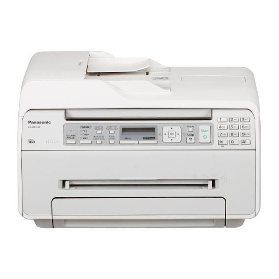
KX-MB1520FX7/KX-MB1520FX8/KX-MB1520FXW/KX-MB1530FX7/KX-MB1530FXW 7 Location of Controls and Components 7.1. Overview 7.1.1. Front view (1) Speaker (2) Recording paper exit •The unit can hold up to approximately 30 sheets of printed paper. Remove the printed paper before the recording paper exit becomes full. -
Page 81: Rear View
KX-MB1520FX7/KX-MB1520FX8/KX-MB1520FXW/KX-MB1530FX7/KX-MB1530FXW 7.1.2. Rear view (1) Rear cover (2) Power switch (3) Power inlet (4) USB interface connector... -
Page 82: Control Panel
KX-MB1520FX7/KX-MB1520FX8/KX-MB1520FXW/KX-MB1530FX7/KX-MB1530FXW 7.2. Control Panel (1) Quality (2) Caller ID (2) Page Layout (3) Menu (4) Mic (4) For beep sounds (5) Fax Auto Answer (6) Fax/Copy/Scan (7) Redial (7) P(Pause) (7) Copy Size (8) Flash (8) Zoom (9) Mute (10) SP-Phone... -
Page 83: Installation Instructions
KX-MB1520FX7/KX-MB1520FX8/KX-MB1520FXW/KX-MB1530FX7/KX-MB1530FXW 8 Installation Instructions 8.1. Installation 8.1.1. Installation Space The space required to install the unit is shown below. The dimensions given are necessary for the unit to operate efficiently. Note: • Avoid excessive heat or humidity. • Use the unit within the following ranges of temperature and humidity. -
Page 84: Recording Paper
KX-MB1520FX7/KX-MB1520FX8/KX-MB1520FXW/KX-MB1530FX7/KX-MB1530FXW 8.1.2. Recording Paper Note for recording paper: • We recommend that you test paper (especially special sizes and types of paper) on the unit before purchasing large quantities. • Do not use the following types of paper: - Paper with cotton and/or fibre content that is over 20%, such as letterhead paper or paper used for resumes... - Page 85 KX-MB1520FX7/KX-MB1520FX8/KX-MB1520FXW/KX-MB1530FX7/KX-MB1530FXW Load the paper, print-side down (1). Important: • Push down to lock the plate (2) in the paper input tray, if neces- sary. Adjust the recording paper guides. Pinch the rear guide (1), then slide it to match the paper size mark. Pinch the right guide (2), then slide it to adjust the width to the size of the recording paper.
- Page 86 KX-MB1520FX7/KX-MB1520FX8/KX-MB1520FXW/KX-MB1530FX7/KX-MB1530FXW To expand the paper exit You can temporarily expand the paper exit before printing. - When printing on small sized paper, you can pull it out easily. - When printing several pages (20 to 30 pages), paper stacking will be supported.
-
Page 87: Documents The Unit Can Send
KX-MB1520FX7/KX-MB1520FX8/KX-MB1520FXW/KX-MB1530FX7/KX-MB1530FXW 8.1.2.2. Manual input tray You can use the manual input tray for printing with the computer and for copying. It can hold one page at a time. When printing or copying multiple pages, add the next page after the first page has been fed into the unit. -
Page 88: Using The Automatic Document Feeder (Kx-Mb1530 Only)
KX-MB1520FX7/KX-MB1520FX8/KX-MB1520FXW/KX-MB1530FX7/KX-MB1530FXW 8.1.4. Using the automatic document feeder (KX-MB1530 only) Open the document sub tray (1) by pressing its centre part (2). Insert the document (up to 15 pages) FACE DOWN into the feeder until a single beep is heard. Adjust the width of the document guides (3) to fit the actual size of the document. -
Page 89: Toner Cartridge
• Do not add toner to the toner cartridge. We cannot be responsible for any damage to the unit or degradation of print quality which may occur from the use of a non-Panasonic toner cartridge. Remove the toner cartridge from the protective bag. - Page 90 KX-MB1520FX7/KX-MB1520FX8/KX-MB1520FXW/KX-MB1530FX7/KX-MB1530FXW Detach the orange protective cover (1) from the toner cartridge. • Do not touch or scratch the drum surface. Open the front cover (1). Hold the toner cartridge (1) by the centre handle, then insert firmly to lock into place.
-
Page 91: When To Replace The Toner Cartridge
(P.256)). If the printing quality is still poor or “DRUM LIFE OVER CHANGE CARTRIDGE” appears on the display, replace the toner cartridge. Note: • To ensure that the unit operates properly, we recommend the use of Panasonic toner cartridges. (Refer to Optional Accesso- ries (P.12)). Waste disposal method Waste material should be disposed of under conditions which meet all national and local environmental regulations. -
Page 92: Required Computer Environment
8.1.6. Required computer environment Panasonic Multi-Function Station software enables the unit to carry out the following functions: - Printing on plain paper, thin and thick paper and labels - Previewing documents and changing printer settings before printing (Easy Print Utility) - Scanning documents and converting an image into text with OCR software (not supplied) ®... -
Page 93: Installing Multi-Function Station On A Computer
KX-MB1520FX7/KX-MB1520FX8/KX-MB1520FXW/KX-MB1530FX7/KX-MB1530FXW 8.1.7. Installing Multi-Function Station on a computer • Install Multi-Function Station (CD-ROM) before connecting the unit to a computer with the USB cable. If the unit is con- nected to a computer with the USB cable before installing Multi-Function Station, the [Found New Hardware Wizard] dialogue box will appear. -
Page 94: Connections
KX-MB1520FX7/KX-MB1520FX8/KX-MB1520FXW/KX-MB1530FX7/KX-MB1530FXW 8.2. Connections Caution: • When you operate this product, the power outlet should be near the product and easily accessible. (1) Power cord •Connect to a power outlet. (220-240 V, 50/60 Hz). (2) Telephone line cord (not supplied) •Connect to a single telephone line jack. - Page 95 KX-MB1520FX7/KX-MB1520FX8/KX-MB1520FXW/KX-MB1530FX7/KX-MB1530FXW Note: • Do not place any objects within 10 cm of the right and left sides of the unit. • Do not cover slots and openings on the unit. They are provided for ventilation and protection against overheating. • If any other device is connected to the same telephone line, this unit may disturb the network condition of the device.
-
Page 96: Operating Instructions
KX-MB1520FX7/KX-MB1520FX8/KX-MB1520FXW/KX-MB1530FX7/KX-MB1530FXW 9 Operating Instructions 9.1. Your Logo You can program your logo (name, company name, etc.) so that it appears on the top of each page sent. -
Page 97: Character Entry
KX-MB1520FX7/KX-MB1520FX8/KX-MB1520FXW/KX-MB1530FX7/KX-MB1530FXW 9.2. Character entry The dial keypad is used to enter characters and numbers. - Press [ ] or [ ] to move the cursor. - Press the dial keys to enter characters and numbers. - Press [Stop] to erase the character or number highlighted by the cursor. Press and hold [Stop] to erase all characters or num- bers. -
Page 98: Test Mode
KX-MB1520FX7/KX-MB1520FX8/KX-MB1520FXW/KX-MB1530FX7/KX-MB1530FXW 10 Test Mode 10.1. Test Functions The codes listed below can be used to perform simple checks of some of the unit’s functions. When complaints are received from customers, they provide an effective tool for identifying the locations and causes of malfunctions. -
Page 99: Dtmf Single Tone Transmit Selection
KX-MB1520FX7/KX-MB1520FX8/KX-MB1520FXW/KX-MB1530FX7/KX-MB1530FXW Test Mode Type of Mode Code Function Operation after code input SENSOR CHECK Service Mode “8” “1” “5” First of all, press the copy button, and confirm the action of ON/OFF. For each sensor’s operation, refer to Sensors and Switches Section (P.57). -
Page 100: Button Code Table
KX-MB1520FX7/KX-MB1520FX8/KX-MB1520FXW/KX-MB1530FX7/KX-MB1530FXW 10.1.2. Button Code Table... -
Page 101: Print Test Pattern
KX-MB1520FX7/KX-MB1520FX8/KX-MB1520FXW/KX-MB1530FX7/KX-MB1530FXW 10.1.3. Print Test Pattern 1. NO.01 3. NO.03 2. NO.06 • These print test patterns are just image printing, and differ- ent from actual ones. • When it is required to judge the print quality, compare with the printing of a nondefective machine. -
Page 102: Service Mode
KX-MB1520FX7/KX-MB1520FX8/KX-MB1520FXW/KX-MB1530FX7/KX-MB1530FXW 11 Service Mode The programming functions are used to program the various features and functions of the machine, and to test the machine. This facilitates communication between the user and the service man while programming the unit. 11.1. Programming and Lists 11.1.1. -
Page 103: Service Function Table
KX-MB1520FX7/KX-MB1520FX8/KX-MB1520FXW/KX-MB1530FX7/KX-MB1530FXW 11.1.3. Service Function Table Code Function Set Value Effective Default Remarks Range Pause time set X 100 msec 001~600 ---------- Dial speed select 1:10 pps 1, 2 ---------- 2:20 pps V34 transmission start speed 0: Disable If the code 527 is set at 2, the code 507 and 508 1: 33.6... - Page 104 KX-MB1520FX7/KX-MB1520FX8/KX-MB1520FXW/KX-MB1530FX7/KX-MB1530FXW Code Function Set Value Effective Default Remarks Range CNG transmit select 1:OFF Lets you select the CNG output during FAX trans- 2:ALL mission. ALL: CNG is output at phase A. AUTO: 3:AUTO CNG id output only when automatic dialing is per- formed.
-
Page 105: Memory Clear Specification
KX-MB1520FX7/KX-MB1520FX8/KX-MB1520FXW/KX-MB1530FX7/KX-MB1530FXW 11.1.4. Memory Clear Specification Execute Service Mode #550 when you want to reset the all setting data keeping the user information. Execute Service Mode #710 to clear the user information in case that Main Unit is recycled. Note: Please restart a power supply after clearing a memory. -
Page 106: User Mode (The List Below Is An Example Of The System Setup List The Unit Prints Out.)
KX-MB1520FX7/KX-MB1520FX8/KX-MB1520FXW/KX-MB1530FX7/KX-MB1530FXW 11.2. User Mode (The list below is an example of the SYSTEM SETUP LIST the unit prints out.) (KX-MB1520) - Page 107 KX-MB1520FX7/KX-MB1520FX8/KX-MB1520FXW/KX-MB1530FX7/KX-MB1530FXW Note: The above values are the default values.
- Page 108 KX-MB1520FX7/KX-MB1520FX8/KX-MB1520FXW/KX-MB1530FX7/KX-MB1530FXW (KX-MB1530)
- Page 109 KX-MB1520FX7/KX-MB1520FX8/KX-MB1520FXW/KX-MB1530FX7/KX-MB1530FXW Note: The above values are the default values.
-
Page 110: Service Mode Settings (Example Of A Printed Out List)
KX-MB1520FX7/KX-MB1520FX8/KX-MB1520FXW/KX-MB1530FX7/KX-MB1530FXW 11.3. Service Mode Settings (Example of a printed out list) (KX-MB1520) Note: The above values are the default values. (KX-MB1530) Note: The above values are the default values. -
Page 111: History (Example Of A Printed Out List)
KX-MB1520FX7/KX-MB1520FX8/KX-MB1520FXW/KX-MB1530FX7/KX-MB1530FXW 11.4. History (Example of a printed out list) Total Simulated Count : 0000006 Total Print Count : 0000000 Duples Count (10) (11) (12) (13) (14) (15) (16) (17) (18) (24) (19) (20) (21) (22) (23) (27) (25) (26) (28) -
Page 112: Descriptions Of The History Report
KX-MB1520FX7/KX-MB1520FX8/KX-MB1520FXW/KX-MB1530FX7/KX-MB1530FXW 11.4.1. Descriptions of The History Report (1) Usage Time of Receive Mode (Tel Mode) (2) Usage Time of Receive Mode (Fax Mode) (3) Usage Time of Receive Mode (Tel/Fax Mode) (4) Not used (5) Dial Mode (6) Number of Directory Entry... -
Page 113: Troubleshooting Guide
KX-MB1520FX7/KX-MB1520FX8/KX-MB1520FXW/KX-MB1530FX7/KX-MB1530FXW 12 Troubleshooting Guide 12.1. User Recoverable Errors If the unit detects a problem, one or more of the following messages will appear on the display. The explanations given in the [ ] are for servicemen only. DISPLAY MESSAGE CAUSE AND REMEDY •... - Page 114 KX-MB1520FX7/KX-MB1520FX8/KX-MB1520FXW/KX-MB1530FX7/KX-MB1530FXW DISPLAY MESSAGE CAUSE AND REMEDY • The inside of the unit is extremely cold and cannot be operated. Use the unit in a warmer area. • When performing memory transmission, the document being stored exceeded the memory capacity of the unit.
-
Page 115: Remote Programming
KX-MB1520FX7/KX-MB1520FX8/KX-MB1520FXW/KX-MB1530FX7/KX-MB1530FXW 12.2. Remote Programming If, after the call is connected, the customer describes the situation and it is determined that the problem can be corrected by making parameter changes, this function makes it possible to change parameters such as the user code and service code from another fax (using DTMF tones). -
Page 116: Entering The Remote Programming Mode And Changing Service Codes
KX-MB1520FX7/KX-MB1520FX8/KX-MB1520FXW/KX-MB1530FX7/KX-MB1530FXW 12.2.1. Entering the Remote Programming Mode and Changing Service Codes CROSS REFERENCE: Program Mode Table (P.117) -
Page 117: Program Mode Table
KX-MB1520FX7/KX-MB1520FX8/KX-MB1520FXW/KX-MB1530FX7/KX-MB1530FXW 12.2.2. Program Mode Table 12.2.2.1. User Function Basic features Code Function Set Value Default Remote Setting SET DATE & TIME dd/mm/yy hh:mm 01/01/12 YOUR LOGO --------- None YOUR FAX NUMBER --------- None DIALLING MODE 1:PULSE / 2:TONE TONE SET RECALL / FLASH TIME... - Page 118 KX-MB1520FX7/KX-MB1520FX8/KX-MB1520FXW/KX-MB1530FX7/KX-MB1530FXW Copy features Code Function Set Value Default Remote Setting COPY INPUT TRAY 1:#1/ 2:#2 COPY RESOLUTION 1:TEXT/PHOTO / 2:TEXT / 3:PHOTO TEXT/PHOTO PAGE LAYOUT HOLD 1:DISABLED / 2:ENABLED DISABLED ZOOM HOLD 1:DISABLED / 2:ENABLED DISABLED COLLATE HOLD 1:DISABLED / 2:ENABLED...
- Page 119 KX-MB1520FX7/KX-MB1520FX8/KX-MB1520FXW/KX-MB1530FX7/KX-MB1530FXW 12.2.2.2. Service Function Code Function Set Value Default Remote Setting Pause time set 001~600 x 100msec Dial speed 1:10pps / 2:20 pps 10pps V34 transmission start speed 0:Disable/1:33.6/2:31.2/3:28.8/4:26.4/ 33600bps 5:24.0/6:21.6/7:19.2/8:16.8 V34 reception start speed 0:Disable/1:33.6/2:31.2/3:28.8/4:26.4/ 33600bps 5:24.0/6:21.6/7:19.2/8:16.8 Bell signal detect time...
- Page 120 KX-MB1520FX7/KX-MB1520FX8/KX-MB1520FXW/KX-MB1530FX7/KX-MB1530FXW Code Function Set Value Default Remote Setting History list 1:Start --------- Service list 1:Start --------- OK means “can set”. NG means “can not set”. Note: Refer to Service Function Table (P.103) for descriptions of the individual codes. Example: If you want to set value in the “401 PRINT SENDING REPORT”, press the dial key number 1, 2 or 3 corresponding to the Set...
-
Page 121: Troubleshooting Details
KX-MB1520FX7/KX-MB1520FX8/KX-MB1520FXW/KX-MB1530FX7/KX-MB1530FXW 12.3. Troubleshooting Details 12.3.1. Outline Troubleshooting is for recovering quality and reliability by determining the broken component and replacing, adjusting or cleaning it as required. First, determine the problem then decide the troubleshooting method. If you have difficulty finding the broken part, determine which board is broken. -
Page 122: Initialization
KX-MB1520FX7/KX-MB1520FX8/KX-MB1520FXW/KX-MB1530FX7/KX-MB1530FXW 12.3.3. Initialization When the power is on, insert the toner cartridge and close the front cover. The Multi-Function Station will be initialized after the jammed paper is removed. It takes about 10 seconds (depends on the condition). -
Page 123: Simple Check List
KX-MB1520FX7/KX-MB1520FX8/KX-MB1520FXW/KX-MB1530FX7/KX-MB1530FXW 12.3.4. Simple Check List Note: Check according to the service code referring to Test Functions (P.98). -
Page 124: Simplified Troubleshooting Guide
KX-MB1520FX7/KX-MB1520FX8/KX-MB1520FXW/KX-MB1530FX7/KX-MB1530FXW 12.3.5. Simplified Troubleshooting Guide 12.3.5.1. Printing Symptom Cause Countermeasure Ghost Image (P.133) Failed toner cartridge Replace toner cartridge Failed transfer unit Check the transfer roller and spring Failed the high-voltage terminal Check the high-voltage terminal Failed the high voltage power supply board Go to High Voltage Section (P.187) - Page 125 KX-MB1520FX7/KX-MB1520FX8/KX-MB1520FXW/KX-MB1530FX7/KX-MB1530FXW 12.3.5.2. Recording Paper Feed Symptom Cause Countermeasure Multiple Feed (P.139) Dirty or failed the pickup roller Clean or replace the pickup roller Dirty or failed the pickup rubber Clean or replace the separation rubber The Recording Paper Is Dirty the pressure roller or the heat roller Clean the pressure roller and the heat roller Waved or Wrinkled (P.140)
- Page 126 KX-MB1520FX7/KX-MB1520FX8/KX-MB1520FXW/KX-MB1530FX7/KX-MB1530FXW 12.3.5.3. Copy and FAX Symptom Cause Countermeasure No Document Feed (No Failed the document sensor lever Replace the document sensor lever Document Feed, Docu- Failed the document sensor Go to Sensor Section (P.173) ment JAM and Multiple Dirty or failed the separation roller Clean or replace the separation roller Document Feed.) (P.145)
-
Page 127: Call Service Troubleshooting Guide
KX-MB1520FX7/KX-MB1520FX8/KX-MB1520FXW/KX-MB1530FX7/KX-MB1530FXW 12.3.6. CALL SERVICE Troubleshooting Guide There are 5 kinds of Call Service messages. Display message Error Point When the power is OFF, Service mode message disappears. 12.3.6.1. Call Service 1 Polygon in LSU *639 12.3.6.2. Call Service 2 Laser in LSU *639 12.3.6.3. -
Page 128: Call Service
KX-MB1520FX7/KX-MB1520FX8/KX-MB1520FXW/KX-MB1530FX7/KX-MB1530FXW 12.3.6.1. CALL SERVICE 1 "CALL SERVICE 1" means that the polygon motor inside the LSU does not rotate. The rotation of the polygon motor is detected by IC300-H25pin (NREADY). Note: Refer to LSU (Laser Scanning Unit) Section (P.55) for technical description. - Page 129 KX-MB1520FX7/KX-MB1520FX8/KX-MB1520FXW/KX-MB1530FX7/KX-MB1530FXW 12.3.6.2. CALL SERVICE 2 "CALL SERVICE 2" means that the synchronous signal out of the LSU cannot be detected. The synchronous signal out of the LSU is detected by IC 300-G23pin. (NHSYNC) Note: As for the "Pulse" waveform of the above flow chart, see the timing chart in LSU (Laser Scanning Unit) Section (P.55).
- Page 130 KX-MB1520FX7/KX-MB1520FX8/KX-MB1520FXW/KX-MB1530FX7/KX-MB1530FXW 12.3.6.3. CALL SERVICE 3 "CALL SERVICE 3" means that the temperature of the fuser does not rise up to or exceed a constant temperature. The temperature is monitored with the thermistor inside the fuser and detected with the voltage input into IC 300-D19.
- Page 131 KX-MB1520FX7/KX-MB1520FX8/KX-MB1520FXW/KX-MB1530FX7/KX-MB1530FXW 12.3.6.4. CALL SERVICE 4 "CALL SERVICE 4" means that the FAN does not rotate or the rotation of the FAN cannot be detected normally. Note: Refer to FAN Motor Section (P.50) for technical description.
- Page 132 KX-MB1520FX7/KX-MB1520FX8/KX-MB1520FXW/KX-MB1530FX7/KX-MB1530FXW 12.3.6.5. CALL SERVICE 17 “CALL SERVICE 17” means that the First use sensor problem. Especially "CALL SERVICE 17" is appeared when the fuse which is installed in the Drum Unit PCB is not blown out within a specific time.
-
Page 133: Print
KX-MB1520FX7/KX-MB1520FX8/KX-MB1520FXW/KX-MB1530FX7/KX-MB1530FXW 12.3.7. Print 12.3.7.1. Ghost Image CROSS REFERENCE: High Voltage Section (P.187) Power Supply Board Section (P.78) - Page 134 KX-MB1520FX7/KX-MB1520FX8/KX-MB1520FXW/KX-MB1530FX7/KX-MB1530FXW 12.3.7.2. Dark or White Vertical Line Note: When wiping the cover glass, reflecting mirror, use a dry and soft cloth.
- Page 135 KX-MB1520FX7/KX-MB1520FX8/KX-MB1520FXW/KX-MB1530FX7/KX-MB1530FXW 12.3.7.3. Dark or White Horizontal Line CROSS REFERENCE: High Voltage Section (P.187)
- Page 136 KX-MB1520FX7/KX-MB1520FX8/KX-MB1520FXW/KX-MB1530FX7/KX-MB1530FXW 12.3.7.4. Dirty or Half Darkness Background CROSS REFERENCE: High Voltage Section (P.187)
-
Page 137: Black Print
KX-MB1520FX7/KX-MB1520FX8/KX-MB1520FXW/KX-MB1530FX7/KX-MB1530FXW 12.3.7.5. Black Print CROSS REFERENCE: High Voltage Section (P.187) LSU (Laser Scanning Unit) Section (P.55) -
Page 138: Light Print
KX-MB1520FX7/KX-MB1520FX8/KX-MB1520FXW/KX-MB1530FX7/KX-MB1530FXW 12.3.7.6. Light Print CROSS REFERENCE: High Voltage Section (P.187) -
Page 139: Recording Paper Feed
KX-MB1520FX7/KX-MB1520FX8/KX-MB1520FXW/KX-MB1530FX7/KX-MB1530FXW 12.3.7.7. Black or White Point 12.3.8. Recording Paper Feed 12.3.8.1. Multiple Feed... - Page 140 KX-MB1520FX7/KX-MB1520FX8/KX-MB1520FXW/KX-MB1530FX7/KX-MB1530FXW 12.3.8.2. The Recording Paper Is Waved or Wrinkled...
- Page 141 KX-MB1520FX7/KX-MB1520FX8/KX-MB1520FXW/KX-MB1530FX7/KX-MB1530FXW 12.3.8.3. Skew...
- Page 142 KX-MB1520FX7/KX-MB1520FX8/KX-MB1520FXW/KX-MB1530FX7/KX-MB1530FXW 12.3.8.4. The Recording Paper Does Not Feed CROSS REFERENCE: Sensor Section (P.173) Motor Section (P.178)
- Page 143 KX-MB1520FX7/KX-MB1520FX8/KX-MB1520FXW/KX-MB1530FX7/KX-MB1530FXW 12.3.8.5. The Recording Paper Jam...
- Page 144 KX-MB1520FX7/KX-MB1520FX8/KX-MB1520FXW/KX-MB1530FX7/KX-MB1530FXW CROSS REFERENCE: FAN Motor Section (P.50) When the recording paper jam is occurred, the service mode *630 distinguishes the cause. 0:No Jam 1:Exit Sensor turns ON, though not under the conditions for ON. 2:Exit Sensor turns OFF, though not under the conditions for OFF.
-
Page 145: Adf (Auto Document Feed) Section (Kx-Mb1530 Only)
KX-MB1520FX7/KX-MB1520FX8/KX-MB1520FXW/KX-MB1530FX7/KX-MB1530FXW 12.3.9. ADF (Auto document feed) Section (KX-MB1530 ONLY) 12.3.9.1. No Document Feed, Document JAM and Multiple Document Feed. - Page 146 KX-MB1520FX7/KX-MB1520FX8/KX-MB1520FXW/KX-MB1530FX7/KX-MB1530FXW CROSS REFERENCE: Sensor Section (P.173) Motor Section (P.178)
- Page 147 KX-MB1520FX7/KX-MB1520FX8/KX-MB1520FXW/KX-MB1530FX7/KX-MB1530FXW 12.3.9.2. Skew (ADF)
-
Page 148: Scanner Glass
KX-MB1520FX7/KX-MB1520FX8/KX-MB1520FXW/KX-MB1530FX7/KX-MB1530FXW 12.3.9.3. Scanner Glass 12.3.9.4. The Sent FAX Data is Skewed CROSS REFERENCE: Skew (ADF) (P.147) 12.3.9.5. The Received FAX Data is Skewed CROSS REFERENCE: Skew (P.141) - Page 149 KX-MB1520FX7/KX-MB1520FX8/KX-MB1520FXW/KX-MB1530FX7/KX-MB1530FXW 12.3.9.6. The Received or Copied Data is Expanded 12.3.9.7. Black or White Vertical Line is Copied...
- Page 150 KX-MB1520FX7/KX-MB1520FX8/KX-MB1520FXW/KX-MB1530FX7/KX-MB1530FXW 12.3.9.8. An Abnormal Image is Copied CROSS REFERENCE: CIS Control Section (P.183)
-
Page 151: Communication Section
KX-MB1520FX7/KX-MB1520FX8/KX-MB1520FXW/KX-MB1530FX7/KX-MB1530FXW 12.3.10. Communication Section Find the problem in the table shown below, and refer to the corresponding troubleshooting procedure in Defective Facsimile Sec- tion (P.152). Symptom Content Possible cause The paper dose not feed properly when faxing. Troubleshooting Problem with the feeding mecha- nism. - Page 152 KX-MB1520FX7/KX-MB1520FX8/KX-MB1520FXW/KX-MB1530FX7/KX-MB1530FXW 12.3.10.1. Defective Facsimile Section 12.3.10.1.1. Transmit Problem CROSS REFERENCE: Operation Panel Section (P.173) Cleaning the White Plates and Glass (P.241) ADF (Auto document feed) Section (KX-MB1530 ONLY) (P.145)
- Page 153 KX-MB1520FX7/KX-MB1520FX8/KX-MB1520FXW/KX-MB1530FX7/KX-MB1530FXW 12.3.10.1.2. Sometime There is a Transmit Problem Note: “596: Transmit level set” represents a service code. Refer to the Service Function Table (P.103). “717: Transmit speed select” represents a service code. Refer to the Service Function Table (P.103).
- Page 154 KX-MB1520FX7/KX-MB1520FX8/KX-MB1520FXW/KX-MB1530FX7/KX-MB1530FXW 12.3.10.1.3. Receive Problem Confirm the following before starting troubleshooting. • Is the recording paper installed properly? Refer to the next page. Note: “596: Transmit level set” represents a service code. Refer to the Service Function Table (P.103). “718: Receive speed select” represents a service code. Refer to the Service Function Table (P.103).
- Page 155 KX-MB1520FX7/KX-MB1520FX8/KX-MB1520FXW/KX-MB1530FX7/KX-MB1530FXW 12.3.10.1.4. The Unit Can Copy, But Cannot Transmit/Receive CROSS REFERENCE: Test Functions (P.98) Check Sheet (P.170)
-
Page 156: Special Service Journal Reports
KX-MB1520FX7/KX-MB1520FX8/KX-MB1520FXW/KX-MB1530FX7/KX-MB1530FXW 12.3.11. Special Service Journal Reports Journal 2 and Journal 3 shown below, which are special journals giving the additional detailed information about the latest 30 com- munications, can be printed by Service Code 881 or 882. Remote printing function for the journal reports (JOURNAL, JOURNAL 2 and JOURNAL 3) is also available for service technicians. - Page 157 KX-MB1520FX7/KX-MB1520FX8/KX-MB1520FXW/KX-MB1530FX7/KX-MB1530FXW 12.3.11.1. Journal 2 Refer to JOURNAL 2 in Printout Example (P.158). Journal 2 displays the additional detailed information about the last 35 communications. Descriptions: (1) RCV. MODE Indicates which receive mode the unit was in when the unit received a fax message.
- Page 158 KX-MB1520FX7/KX-MB1520FX8/KX-MB1520FXW/KX-MB1530FX7/KX-MB1530FXW 12.3.11.2. Journal 3 Refer to JOURNAL 3 in Printout Example (P.158). Description (6) ENCODE Compression Code: MH/MR/MMR (7) MSLT MSLT means Minimum Scan Line Time. Used only at the factory. (8) EQM (RX) EQM means Eye Quality Monitor. Used only at the factory.
- Page 159 KX-MB1520FX7/KX-MB1520FX8/KX-MB1520FXW/KX-MB1530FX7/KX-MB1530FXW...
- Page 160 KX-MB1520FX7/KX-MB1520FX8/KX-MB1520FXW/KX-MB1530FX7/KX-MB1530FXW 12.3.11.4. How To Output The Journal Report 1. Press the MENU button 4 times. 2. Press “#”, then “2”. 3. Press the SET button. 4. The report prints out. CROSS REFERENCE: Features (P.13) Error code table: (1) CODE (2) RESULT...
- Page 161 KX-MB1520FX7/KX-MB1520FX8/KX-MB1520FXW/KX-MB1530FX7/KX-MB1530FXW...
- Page 162 KX-MB1520FX7/KX-MB1520FX8/KX-MB1520FXW/KX-MB1530FX7/KX-MB1530FXW CROSS REFERENCE: Test Functions (P.98)
- Page 163 KX-MB1520FX7/KX-MB1520FX8/KX-MB1520FXW/KX-MB1530FX7/KX-MB1530FXW CROSS REFERENCE: Test Functions (P.98)
- Page 164 KX-MB1520FX7/KX-MB1520FX8/KX-MB1520FXW/KX-MB1530FX7/KX-MB1530FXW CROSS REFERENCE: Test Functions (P.98)
- Page 165 KX-MB1520FX7/KX-MB1520FX8/KX-MB1520FXW/KX-MB1530FX7/KX-MB1530FXW CROSS REFERENCE: Test Functions (P.98)
- Page 166 KX-MB1520FX7/KX-MB1520FX8/KX-MB1520FXW/KX-MB1530FX7/KX-MB1530FXW...
- Page 167 KX-MB1520FX7/KX-MB1520FX8/KX-MB1520FXW/KX-MB1530FX7/KX-MB1530FXW...
- Page 168 KX-MB1520FX7/KX-MB1520FX8/KX-MB1520FXW/KX-MB1530FX7/KX-MB1530FXW CROSS REFERENCE: Test Functions (P.98)
-
Page 169: Initializing Error
KX-MB1520FX7/KX-MB1520FX8/KX-MB1520FXW/KX-MB1530FX7/KX-MB1530FXW 12.3.12. Initializing Error After the power is turned on, the SOC (IC300) initializes and checks each IC. The ROM (IC402) and SDRAM (IC400) are checked. If initialization fails for the ICs, the system will not boot up. In this case, please find the cause as follows. -
Page 170: Analog Section
KX-MB1520FX7/KX-MB1520FX8/KX-MB1520FXW/KX-MB1530FX7/KX-MB1530FXW 12.3.13. Analog Section This chapter provides the testing procedures required for the analog parts. A signal route to be tested is determined depending upon purposes. For example, the handset TX route begins at the handset microphone and the signal is output to the telephone line. - Page 171 KX-MB1520FX7/KX-MB1520FX8/KX-MB1520FXW/KX-MB1530FX7/KX-MB1530FXW 12.3.13.2. Detective ITS (Integrated Telephone System) Section 1. No speakerphone transmission / reception Perform a signal test in the ITS or the NCU section and locate a defective point (where the signal disappears) on each route between the microphone and the telephone line (sending), or between the telephone line and the speaker (receiving). Check the components at that point.
- Page 172 KX-MB1520FX7/KX-MB1520FX8/KX-MB1520FXW/KX-MB1530FX7/KX-MB1530FXW 4. No tone dialing CROSS REFERENCE: Check Sheet (P.170) 12.3.13.3. Detective TAM Interface Section 1. The FAX turns on, but does not arrive through TAM. CROSS REFERENCE: TAM Interface Circuit (P.31) 2. A FAX is received, but won't switch from TAM to FAX.
-
Page 173: Operation Panel Section
KX-MB1520FX7/KX-MB1520FX8/KX-MB1520FXW/KX-MB1530FX7/KX-MB1530FXW 12.3.14. Operation Panel Section Refer to Test Functions (P.98). 1. NO KEY OPERATION 2. NO LCD INDICATION CROSS REFERENCE: Test Functions (P.98) 12.3.15. Sensor Section Refer to SENSORS AND SWITCHES for the circuit description. Perform an SENSOR CHECK to determine if the sensor is operating correctly. - Page 174 KX-MB1520FX7/KX-MB1520FX8/KX-MB1520FXW/KX-MB1530FX7/KX-MB1530FXW 2. Check the print timing sensor..“PAPER JAMMED” 3. Check the paper exit sensor ..“PAPER JAMMED” 4. Check the Interlock switch ..“FRONT COVER OPEN” 5. Check the toner sensor ..“TONER LOW”, “TONER EMPTY”, “CHANGE CARTRIDGE”...
- Page 175 KX-MB1520FX7/KX-MB1520FX8/KX-MB1520FXW/KX-MB1530FX7/KX-MB1530FXW Toner detection flow...
- Page 176 KX-MB1520FX7/KX-MB1520FX8/KX-MB1520FXW/KX-MB1530FX7/KX-MB1530FXW 6. Drum Life detection flow...
- Page 177 KX-MB1520FX7/KX-MB1520FX8/KX-MB1520FXW/KX-MB1530FX7/KX-MB1530FXW 7. Check the read position sensor ..“CHECK DOCUMENT” (KX-MB1530 ONLY) 8. Check the document sensor (KX-MB1530 ONLY)
-
Page 178: Motor Section
KX-MB1520FX7/KX-MB1520FX8/KX-MB1520FXW/KX-MB1530FX7/KX-MB1530FXW 12.3.16. Motor Section 12.3.16.1. Main Motor... - Page 179 KX-MB1520FX7/KX-MB1520FX8/KX-MB1520FXW/KX-MB1530FX7/KX-MB1530FXW 12.3.16.2. FB Motor (KX-MB1520 only)
- Page 180 KX-MB1520FX7/KX-MB1520FX8/KX-MB1520FXW/KX-MB1530FX7/KX-MB1530FXW 12.3.16.3. FB MOTOR (KX-MB1530 only)
- Page 181 KX-MB1520FX7/KX-MB1520FX8/KX-MB1520FXW/KX-MB1530FX7/KX-MB1530FXW 12.3.16.4. ADF MOTOR (KX-MB1530 only)
-
Page 182: Lsu Section
KX-MB1520FX7/KX-MB1520FX8/KX-MB1520FXW/KX-MB1530FX7/KX-MB1530FXW 12.3.17. LSU Section CROSS REFERENCE: LSU (Laser Scanning Unit) Section (P.55) -
Page 183: Cis Control Section
KX-MB1520FX7/KX-MB1520FX8/KX-MB1520FXW/KX-MB1530FX7/KX-MB1530FXW 12.3.18. CIS Control Section... - Page 184 KX-MB1520FX7/KX-MB1520FX8/KX-MB1520FXW/KX-MB1530FX7/KX-MB1530FXW CROSS REFERENCE: Test Functions (P.98) Refer to Main Board Section (P.197)
-
Page 185: High Voltage Value Check Point
KX-MB1520FX7/KX-MB1520FX8/KX-MB1520FXW/KX-MB1530FX7/KX-MB1530FXW 12.3.19. High Voltage Value Check Point Measurement Procedure 1. Turn off the power supply and remove the left cover of the main unit so that the HVPS is revealed. (To remove the left cover, remove the rear cover in advance. (Refer to How to Remove Rear Cover (P.211).)) 2. - Page 186 KX-MB1520FX7/KX-MB1520FX8/KX-MB1520FXW/KX-MB1530FX7/KX-MB1530FXW Fig. 3 Fig. 4 earth of high pressure probe...
-
Page 187: High Voltage Section
KX-MB1520FX7/KX-MB1520FX8/KX-MB1520FXW/KX-MB1530FX7/KX-MB1530FXW 12.3.20. High Voltage Section 1. Main... - Page 188 KX-MB1520FX7/KX-MB1520FX8/KX-MB1520FXW/KX-MB1530FX7/KX-MB1530FXW 2. CHG 3. TRA (+)
- Page 189 KX-MB1520FX7/KX-MB1520FX8/KX-MB1520FXW/KX-MB1530FX7/KX-MB1530FXW 4. DEV DC...
- Page 190 KX-MB1520FX7/KX-MB1520FX8/KX-MB1520FXW/KX-MB1530FX7/KX-MB1530FXW 5. DEV AC...
- Page 191 KX-MB1520FX7/KX-MB1520FX8/KX-MB1520FXW/KX-MB1530FX7/KX-MB1530FXW 6. TRA (-)
-
Page 192: Usb Section
KX-MB1520FX7/KX-MB1520FX8/KX-MB1520FXW/KX-MB1530FX7/KX-MB1530FXW 12.3.21. USB Section Troubleshooting 1. Confirmation of the PC settings... - Page 193 KX-MB1520FX7/KX-MB1520FX8/KX-MB1520FXW/KX-MB1530FX7/KX-MB1530FXW 2. Confirmation of the main unit...
- Page 194 KX-MB1520FX7/KX-MB1520FX8/KX-MB1520FXW/KX-MB1530FX7/KX-MB1530FXW USB (Universal Serial Bus) block Description This is a USB block for data communication with PC. Two signal lines (D+/D-) are differential signals which work in reverse phase. VBUS: CN300 1pin D-: CN300 2pin D+: CN300 3pin GND: CN300 4pin...
- Page 195 KX-MB1520FX7/KX-MB1520FX8/KX-MB1520FXW/KX-MB1530FX7/KX-MB1530FXW Circuit Diagram (KX-MB1530 only) Sequence of normal operation When USB cable from PC is connected to CN300, VBUS voltage goes up to 5V, and IC300 recognize the connection with PC. Then D+ becomes about 3V: waveform (1)-1 The D+ becomes 0V, then communication between IC300 and PC is started: waveform (2)-1 When a few seconds elapsed after USB cable was inserted into CN300,the unit enters stand-by mode.
- Page 196 KX-MB1520FX7/KX-MB1520FX8/KX-MB1520FXW/KX-MB1530FX7/KX-MB1530FXW Waveform of normal operation...
-
Page 197: Main Board Section
KX-MB1520FX7/KX-MB1520FX8/KX-MB1520FXW/KX-MB1530FX7/KX-MB1530FXW 12.3.22. Main Board Section 3.3V / 1.2V Troubleshooting Guide (1) -
Page 198: Power Supply Board Section
KX-MB1520FX7/KX-MB1520FX8/KX-MB1520FXW/KX-MB1530FX7/KX-MB1530FXW 12.3.23. Power Supply Board Section 12.3.23.1. Key Components For Troubleshooting Check the following parts first: F2, C5, and Q1. This comes from our experience with experimental test. For example: power supply and lightning surge voltage test, with standing voltage test, intentional short circuit test, etc. -
Page 199: Troubleshooting Flow Chart
KX-MB1520FX7/KX-MB1520FX8/KX-MB1520FXW/KX-MB1530FX7/KX-MB1530FXW 12.3.23.2. Troubleshooting Flow Chart... - Page 200 KX-MB1520FX7/KX-MB1520FX8/KX-MB1520FXW/KX-MB1530FX7/KX-MB1530FXW 12.3.23.3. Broken Parts Repair Details (D11-D14) If D11-D14 are short-circuit, F2 will melt (open). In this case, replace all of the parts (D11-D14, F2). (C5) If overvoltage (Approx. 450V) was supplied for a power supply unit, C5 will be broken.
-
Page 201: Recording Paper Jam
KX-MB1520FX7/KX-MB1520FX8/KX-MB1520FXW/KX-MB1530FX7/KX-MB1530FXW 12.4. Recording Paper Jam 12.4.1. When the recording paper has jammed inside of the unit The display will show the following. Caution: • Do not open the paper input tray before opening the front and rear covers as the jammed paper may be pulled and the jam may get worse. - Page 202 KX-MB1520FX7/KX-MB1520FX8/KX-MB1520FXW/KX-MB1530FX7/KX-MB1530FXW 3. Remove the jammed paper (1) carefully by pulling it toward you. Note: • The area near the rear cover (3) may also get warm. 4. Push up the green levers (1) to the original position. 5. Close the rear cover.
- Page 203 KX-MB1520FX7/KX-MB1520FX8/KX-MB1520FXW/KX-MB1530FX7/KX-MB1530FXW 2. Remove the jammed paper (1) carefully by pulling it toward you. • If the recording paper has jammed behind the toner cartridge, remove the toner cartridge (1) first, and remove the jammed paper (2). Then reinsert the toner cartridge into the unit.
-
Page 204: When The Recording Paper Is Not Fed Into The Unit Properly
KX-MB1520FX7/KX-MB1520FX8/KX-MB1520FXW/KX-MB1530FX7/KX-MB1530FXW 12.4.2. When the recording paper is not fed into the unit properly The display will show the following. Pull the paper input tray completely out. Re-load the recording paper. Insert the paper input tray into the unit. Note: • If the message is still displayed, check the recording paper specifications and load the recording paper again. -
Page 205: When The Recording Paper In The Manual Input Tray Is Not Fed Into The Unit Properly
KX-MB1520FX7/KX-MB1520FX8/KX-MB1520FXW/KX-MB1530FX7/KX-MB1530FXW 12.4.3. When the recording paper in the manual input tray is not fed into the unit properly The display will show the following. Remove the recording paper. Re-insert the recording paper. Note: • If the message is still displayed, check the recording paper specifications and re-install recording paper. -
Page 206: Document Jams (Automatic Document Feeder) (Kx-Mb1530 Only)
KX-MB1520FX7/KX-MB1520FX8/KX-MB1520FXW/KX-MB1530FX7/KX-MB1530FXW 12.5. Document jams (Automatic document feeder) (KX-MB1530 only) The display will show the following. Caution: • Do not pull out the jammed document forcibly before lifting the ADF cover. • Be careful not to damage the transparent plastic sheets (1). - Page 207 KX-MB1520FX7/KX-MB1520FX8/KX-MB1520FXW/KX-MB1530FX7/KX-MB1530FXW When the document has jammed near the document exit: • If you cannot remove the jammed document (1), open the docu- ment cover, remove the document, then close the document cover. Close the ADF cover. • Press [Stop] to clear the message.
-
Page 208: Service Fixture & Tools
KX-MB1520FX7/KX-MB1520FX8/KX-MB1520FXW/KX-MB1530FX7/KX-MB1530FXW 13 Service Fixture & Tools How to extend cords When extending cords, you need 2 pairs of A,B (A=connector,B=cord) (One pair is connected to the Main board.) If you do not have 2 pairs, order the necessary parts. How to connect... -
Page 209: Disassembly And Assembly Instructions
KX-MB1520FX7/KX-MB1520FX8/KX-MB1520FXW/KX-MB1530FX7/KX-MB1530FXW 14 Disassembly and Assembly Instructions KX-MB1520 KX-MB1530... -
Page 210: Flow Chart For Disassembly
KX-MB1520FX7/KX-MB1520FX8/KX-MB1520FXW/KX-MB1530FX7/KX-MB1530FXW 14.1. Flow Chart for Disassembly... -
Page 211: How To Remove Rear Cover
KX-MB1520FX7/KX-MB1520FX8/KX-MB1520FXW/KX-MB1530FX7/KX-MB1530FXW 14.2. How to Remove Rear Cover 14.3. How to Remove Front Cover... -
Page 212: How To Remove Right Cover
KX-MB1520FX7/KX-MB1520FX8/KX-MB1520FXW/KX-MB1530FX7/KX-MB1530FXW 14.4. How to Remove Right Cover... -
Page 213: How To Remove Left Cover
KX-MB1520FX7/KX-MB1520FX8/KX-MB1520FXW/KX-MB1530FX7/KX-MB1530FXW 14.5. How to Remove Left Cover... -
Page 214: How To Remove Fb Unit (Kx-Mb1520 Only)
KX-MB1520FX7/KX-MB1520FX8/KX-MB1520FXW/KX-MB1530FX7/KX-MB1530FXW 14.6. How to Remove FB Unit (KX-MB1520 only) -
Page 215: How To Remove Fb Unit (Kx-Mb1530 Only)
KX-MB1520FX7/KX-MB1520FX8/KX-MB1520FXW/KX-MB1530FX7/KX-MB1530FXW 14.7. How to Remove FB Unit (KX-MB1530 only) -
Page 216: How To Remove Upper Cabinet Cover
KX-MB1520FX7/KX-MB1520FX8/KX-MB1520FXW/KX-MB1530FX7/KX-MB1530FXW 14.8. How to Remove Upper Cabinet Cover... -
Page 217: How To Remove Bottom Plate
KX-MB1520FX7/KX-MB1520FX8/KX-MB1520FXW/KX-MB1530FX7/KX-MB1530FXW 14.9. How to Remove Bottom Plate... -
Page 218: How To Remove Lvps
KX-MB1520FX7/KX-MB1520FX8/KX-MB1520FXW/KX-MB1530FX7/KX-MB1530FXW 14.10. How to Remove LVPS... -
Page 219: How To Remove Fuser Unit
KX-MB1520FX7/KX-MB1520FX8/KX-MB1520FXW/KX-MB1530FX7/KX-MB1530FXW 14.11. How to Remove Fuser Unit 14.12. How to Remove Main Board, Fan, HVPS and Inter-lock Board... -
Page 220: How To Remove Main Board And Shield Cover
KX-MB1520FX7/KX-MB1520FX8/KX-MB1520FXW/KX-MB1530FX7/KX-MB1530FXW 14.13. How to Remove Main Board and Shield Cover 14.14. How to Remove Drive Unit... -
Page 221: How To Remove Clutch Gear Cover
KX-MB1520FX7/KX-MB1520FX8/KX-MB1520FXW/KX-MB1530FX7/KX-MB1530FXW 14.15. How to Remove Clutch Gear Cover... -
Page 222: How To Remove Pick-Up Roller
KX-MB1520FX7/KX-MB1520FX8/KX-MB1520FXW/KX-MB1530FX7/KX-MB1530FXW 14.16. How to Remove Pick-up Roller... -
Page 223: How To Remove Operation Panel Unit
KX-MB1520FX7/KX-MB1520FX8/KX-MB1520FXW/KX-MB1530FX7/KX-MB1530FXW 14.17. How to Remove Operation Panel Unit... -
Page 224: How To Remove Adf Unit (Kx-Mb1530 Only)
KX-MB1520FX7/KX-MB1520FX8/KX-MB1520FXW/KX-MB1530FX7/KX-MB1530FXW 14.18. How to Remove ADF Unit (KX-MB1530 only) -
Page 225: How To Disassemble Fb Unit (Kx-Mb1520 Only)
KX-MB1520FX7/KX-MB1520FX8/KX-MB1520FXW/KX-MB1530FX7/KX-MB1530FXW 14.19. How to Disassemble FB Unit (KX-MB1520 only) -
Page 226: How To Disassemble Fb Unit (Kx-Mb1530 Only)
KX-MB1520FX7/KX-MB1520FX8/KX-MB1520FXW/KX-MB1530FX7/KX-MB1530FXW 14.20. How to Disassemble FB Unit (KX-MB1530 only) -
Page 227: How To Take Off Glass Pad (Kx-Mb1530 Only)
KX-MB1520FX7/KX-MB1520FX8/KX-MB1520FXW/KX-MB1530FX7/KX-MB1530FXW 14.21. How to Take off glass pad (KX-MB1530 only) -
Page 228: How To Remove Conveyer Cover Unit (Kx-Mb1530 Only)
KX-MB1520FX7/KX-MB1520FX8/KX-MB1520FXW/KX-MB1530FX7/KX-MB1530FXW 14.22. How to Remove Conveyer Cover Unit (KX-MB1530 only) -
Page 229: How To Remove Lsu And Glasses
KX-MB1520FX7/KX-MB1520FX8/KX-MB1520FXW/KX-MB1530FX7/KX-MB1530FXW 14.23. How to Remove LSU and Glasses... -
Page 230: Installation Position Of The Lead
KX-MB1520FX7/KX-MB1520FX8/KX-MB1520FXW/KX-MB1530FX7/KX-MB1530FXW 14.24. Installation Position of The Lead 14.24.1. Main cabinet section... -
Page 231: Side Cabinet Section(1)
KX-MB1520FX7/KX-MB1520FX8/KX-MB1520FXW/KX-MB1530FX7/KX-MB1530FXW 14.24.2. Side cabinet section(1) Assembling detail of Lead /ISLW1, Lead HVPS. The lead is put out in the direction of figure. The connector of each lead is previously inserted. Assembling detail of Unit Board Resis The connector of each lead is previously inserted. -
Page 232: Side Cabinet Section (2)
KX-MB1520FX7/KX-MB1520FX8/KX-MB1520FXW/KX-MB1530FX7/KX-MB1530FXW 14.24.3. Side cabinet section (2) Pass the Lead/Gear through in the figure. Lead/Gear must be hooked in the figure. Wind 2 times to core. Pass the Lead/Gear through in the figure. Lead/Gear must be hooked in the figure. Lead/Gear must be hooked in the figure. -
Page 233: Side Cabinet Section (3)
KX-MB1520FX7/KX-MB1520FX8/KX-MB1520FXW/KX-MB1530FX7/KX-MB1530FXW 14.24.4. Side cabinet section (3) LEAD/OPE is hung on the Pass the Lead HVPS, Lead/ISLW2 hook of Main/Cabinet. through in the figure. Pass the Lead/ISLW2 through in the figure. Pass the Lead/HVPS, Lead/ISLW2, Lead/Gear, Lead of Fan through in the figure. -
Page 234: Side Cabinet Section (4)
KX-MB1520FX7/KX-MB1520FX8/KX-MB1520FXW/KX-MB1530FX7/KX-MB1530FXW 14.24.5. Side cabinet section (4) Routing MOTOR_FB/LEAD and FFC/CIS in Each groove, and connect it. (KX-MB1520) Routing LEAD of ADF unit and FFC/CIS in Each groove, and connect it. (KX-MB1530) Routing LEAD in groove. Routing FFC/CIS in groove. FFC/CIS... -
Page 235: Side Cabinet Section (5)
KX-MB1520FX7/KX-MB1520FX8/KX-MB1520FXW/KX-MB1530FX7/KX-MB1530FXW 14.24.6. Side cabinet section (5) Wind 2 times to core. Install SPEAKER in this direction Wind 1 times to hook . -
Page 236: Fuser Section
KX-MB1520FX7/KX-MB1520FX8/KX-MB1520FXW/KX-MB1530FX7/KX-MB1530FXW 14.24.7. Fuser section... -
Page 237: Adf Section (Kx-Mb1530 Only)
KX-MB1520FX7/KX-MB1520FX8/KX-MB1520FXW/KX-MB1530FX7/KX-MB1530FXW 14.24.8. ADF section (KX-MB1530 only) Spring/Detection lever instaling method :Contact with shaft :It hooks on Spring Roller Support 1 The lead is put in the ditch of the base. The part of the UL tape is put in the ditch of PLATE/MOTOR. -
Page 238: Power Supply Unit Section
KX-MB1520FX7/KX-MB1520FX8/KX-MB1520FXW/KX-MB1530FX7/KX-MB1530FXW 14.24.9. Power supply unit section LEAD/AC EARTH SCREW Terminal of Harness Washer PLATE COVER SMPS Install the earth lead on the top and bottom so as not to mistake. return torque :0.2N.m(2.04Kgf.cm)~0.4N.m(4.08Kgf.cm) The lead must not protrude beyond the sheet metal edge side. -
Page 239: Maintenance
KX-MB1520FX7/KX-MB1520FX8/KX-MB1520FXW/KX-MB1530FX7/KX-MB1530FXW 15 Maintenance 15.1. Maintenance Items and Component Locations 15.1.1. Outline MAINTENANCE AND REPAIRS ARE PERFORMED USING THE FOLLOWING STEPS. 1. Periodic maintenance Inspect the equipment periodically and if necessary, clean any contaminated parts. 2. Check for breakdowns Look for problems and consider how they arose. - Page 240 KX-MB1520FX7/KX-MB1520FX8/KX-MB1520FXW/KX-MB1530FX7/KX-MB1530FXW 15.1.2.2. Maintenance Cycle (Document & Paper) Item Cleaning Cycle Pickup Roller (Ref No.120) ------------ Transfer Roller (Ref.No.140) ------------ Registration Roller (Ref.No.149) 3 months Heat Roller (Ref.No.75) ------------ Exit Roller (Ref.No.88) 3 months If each part has got dirty, clean it with a damp cloth then dry thoroughly.
-
Page 241: Maintenance
KX-MB1520FX7/KX-MB1520FX8/KX-MB1520FXW/KX-MB1530FX7/KX-MB1530FXW 15.2. Maintenance 15.2.1. Cleaning the White Plates and Glass Clean the white plates and glass when a black line, a white line or a dirty pattern appears on: — your recording paper, — the original document, — the scanned data, or —... - Page 242 KX-MB1520FX7/KX-MB1520FX8/KX-MB1520FXW/KX-MB1530FX7/KX-MB1530FXW Hold the document cover while cleaning the white plates (1) and the scanner glass (2). Close the document cover.
-
Page 243: Cleaning The Document Feeder Rollers (Kx-Mb1530 Only)
KX-MB1520FX7/KX-MB1520FX8/KX-MB1520FXW/KX-MB1530FX7/KX-MB1530FXW 15.2.2. Cleaning the document feeder rollers (KX-MB1530 only) Clean the rollers when documents frequently misfeed, or when a line or a dirty pattern appears on documents. Caution: • Do not use paper products, such as paper towels or tissues for cleaning. -
Page 244: Printing Operation Principle
KX-MB1520FX7/KX-MB1520FX8/KX-MB1520FXW/KX-MB1530FX7/KX-MB1530FXW 15.3. Printing Operation Principle 15.3.1. Process Chart and Process BIAS 15.3.2. Charging Charging is the stage that keeps the surface of the sensitive drum a fixed electric potential. The sensitive drum is the Organic Photo Conductor (OPC), which is a electric conductive cylinder whose surface is covered with the Charge Generation Transfer Layer (CGL) and charge Transfer Layer (CTL). -
Page 245: Exposing
KX-MB1520FX7/KX-MB1520FX8/KX-MB1520FXW/KX-MB1530FX7/KX-MB1530FXW 15.3.3. Exposing When the drum which is charged with the fixed electric charge is irradiated by the laser beam, the plus charge and minus charge are generated at the Charge Generation Transfer Layer. Passing through the Charge Transfer Layer which conducts the plus charge, the minus-charged drum's surface is neutralized to be skipped. -
Page 246: Developing And Transcription
KX-MB1520FX7/KX-MB1520FX8/KX-MB1520FXW/KX-MB1530FX7/KX-MB1530FXW 15.3.4. Developing and Transcription The developing is the stage that the OPC drum with an invisible image is changed to visible by the toner. The developer consists of mixing paddle, toner supply roller, developing roller, developing blade, and OPC drum. The bias voltage is added to the developing roller (DC-260V) and toner supply roller (DC-260V). -
Page 247: Cleaning Of Transfer Roller
KX-MB1520FX7/KX-MB1520FX8/KX-MB1520FXW/KX-MB1530FX7/KX-MB1530FXW 15.3.5. Cleaning of Transfer Roller The toner attached to the surface of the OPC drum is transferred to the paper at the transcription stage, but a part of the toner remains. The cleaning is the stage that cleans the remain toner after the transcription stage. The remain toner on the drum and the toner which was attached to the place where the laser beam didn't scan are gathered to the developing roller to be used again. -
Page 248: Fixing
KX-MB1520FX7/KX-MB1520FX8/KX-MB1520FXW/KX-MB1530FX7/KX-MB1530FXW 15.3.6. Fixing On the process of the transfer, the transferred toner is weakly attached on the paper. Fixing means the process to fix the toner on the paper permanently. The fixing part melts the toner at the high temperature using the halogen heater. The toner is fixed on the paper by the heat and pressure through the fixing part with the image. -
Page 249: Terminal Guide Of The Ics Transistors And Diodes
KX-MB1520FX7/KX-MB1520FX8/KX-MB1520FXW/KX-MB1530FX7/KX-MB1530FXW 15.4. Terminal Guide of The ICs Transistors and Diodes 15.4.1. Main Board... -
Page 250: Operation Board
KX-MB1520FX7/KX-MB1520FX8/KX-MB1520FXW/KX-MB1530FX7/KX-MB1530FXW 15.4.2. Operation Board 15.4.3. Inter-lock Board 15.4.4. Gear Board 15.4.5. Toner Sensor Board 15.4.6. High Voltage Power Supply Board... -
Page 251: Low Voltage Power Supply Board
KX-MB1520FX7/KX-MB1520FX8/KX-MB1520FXW/KX-MB1530FX7/KX-MB1530FXW 15.4.7. Low Voltage Power Supply Board... -
Page 252: How To Replace The Flat Package Ic
KX-MB1520FX7/KX-MB1520FX8/KX-MB1520FXW/KX-MB1530FX7/KX-MB1530FXW 15.5. How to Replace the Flat Package IC Even if you do not have the special tools (for example, a spot heater) to remove the Flat IC, with some solder (large amount), a soldering iron and a cutter knife, you can easily remove the ICs that have more than 100 pins. -
Page 253: Procedure
KX-MB1520FX7/KX-MB1520FX8/KX-MB1520FXW/KX-MB1530FX7/KX-MB1530FXW 15.5.3. Procedure 1. Tack the flat pack IC to the PCB by temporarily soldering two diagonally opposite pins in the correct positions on the PCB. *Be certain each pin is located over the correct pad on the PCB. 2. Apply flux to all of the pins on the IC. -
Page 254: Main Board Section
KX-MB1520FX7/KX-MB1520FX8/KX-MB1520FXW/KX-MB1530FX7/KX-MB1530FXW 15.6. Main Board Section When the unit fails to boot up the system, take the troubleshooting procedures very carefully. It may have a serious problem. The symptom: No response when the power is turned on. (No LCD display, and keys are not accepted.) The first step is to check the power source. -
Page 255: Ng Example
KX-MB1520FX7/KX-MB1520FX8/KX-MB1520FXW/KX-MB1530FX7/KX-MB1530FXW 15.6.1. NG Example... -
Page 256: Test Chart
KX-MB1520FX7/KX-MB1520FX8/KX-MB1520FXW/KX-MB1530FX7/KX-MB1530FXW 15.7. Test Chart 15.7.1. ITU-T No.1 Test Chart... -
Page 257: Itu-T No.2 Test Chart
KX-MB1520FX7/KX-MB1520FX8/KX-MB1520FXW/KX-MB1530FX7/KX-MB1530FXW 15.7.2. ITU-T No.2 Test Chart... - Page 258 KX-MB1520FX7/KX-MB1520FX8/KX-MB1520FXW/KX-MB1530FX7/KX-MB1530FXW Memo...
-
Page 259: Schematic Diagram
KX-MB1520FX7/KX-MB1520FX8/KX-MB1520FXW/KX-MB1530FX7/KX-MB1530FXW 16 Schematic Diagram 16.1. For Schematic Diagram Note: 1. DC voltage measurements are taken with an oscilloscope or a tester with a ground. 2. The schematic diagrams and circuit board may be modified at any time with the development of new technology. -
Page 260: Main Board (Kx-Mb1520)
KX-MB1520FX7/KX-MB1520FX8/KX-MB1520FXW/KX-MB1530FX7/KX-MB1530FXW 16.2. Main Board (KX-MB1520) 16.2.1. Main Board (1) IC300 FRMD[0-7] SDMD[0-15] SDMD[0] FRMD[0] SDMD0 FRMD0 FRMA[0-24] SDMD[1] FRMD[1] SDMD1 FRMD1 SDMD[2] RA320 FRMD[2] SDMD2 FRMD2 SDMD[3] FRMD[3] SDMD3 FRMD3 SDMD[4] FRMD[4] SDMD4 FRMD4 SDMD[5] FRMD[5] SDMD5 FRMD5 SDMD[6] RA319... - Page 261 KX-MB1520FX7/KX-MB1520FX8/KX-MB1520FXW/KX-MB1530FX7/KX-MB1530FXW +3.3V IC300 CCDSH C6 15BD102 L360 2:5F AFESEL0 CCDSH NCCDRS B6 L361 2:5F AFESEL1 CCDCLK NCCDCP A5 3:1F L356 15BD471 AA24 CCDCLK A6 AFERST AFERST AA25 AFEVSMP B5 L363 2:5D RING AFEVSMP 3:4E L352 15BD471 AB24 AFERSMP B4 15AG601...
- Page 262 KX-MB1520FX7/KX-MB1520FX8/KX-MB1520FXW/KX-MB1530FX7/KX-MB1530FXW +3.3V FRMD[0-7] FRMA[0] FRMA[17] FRMA[24] NC(A24) NC(A23) FRMA[23] NC(A25) NC(A22) FRMA[16] FRMA[15] *BYTE FRMA[14] VSS2 FRMA[13] DQ15/A-1 FRMA[12] FRMD[7] FRMA[11] DQ14 FRMA[10] FRMD[6] FRMA[9] DQ13 +3.3V FRMA[20] FRMD[5] FRMA[21] DQ12 FRMD[4] NFRWE XSYSRST *RESET FRMA[22] 2:3B;2F;5C DQ11 FRMD[3] *WP/ACC...
- Page 263 KX-MB1520FX7/KX-MB1520FX8/KX-MB1520FXW/KX-MB1530FX7/KX-MB1530FXW Memo...
-
Page 264: Main Board (2)
KX-MB1520FX7/KX-MB1520FX8/KX-MB1520FXW/KX-MB1530FX7/KX-MB1530FXW 16.2.2. Main Board (2) +24V +3.3V +3.3V TO OPE R630 39(1/2W) 12k(1608) Q607 CN511 R616 +3.3V IC504 TO FAN R639 R562 1:1E THRM THRMSTR0 R617 Q609 R563 1:3E Q606 R643 KSTART KSTART Q610 F56k R559 1:3E KTXD R619 470k... - Page 265 KX-MB1520FX7/KX-MB1520FX8/KX-MB1520FXW/KX-MB1530FX7/KX-MB1530FXW R644 1:1E FANON1 +5V_SW +3.3V +1.2V 1:3E FANDET1 +1.2V +24V +3.3V +5VD L800 4.7u Q802 L801 22u IC504 Q801 R801 8.2k C818 +24V K0.22u Q806 R819 F22k R813 F2k R820 +3.3V 1:3D F820 SNPICK R800 Q800 R802 1:3D +24V...
-
Page 266: Main Board (3)
KX-MB1520FX7/KX-MB1520FX8/KX-MB1520FXW/KX-MB1530FX7/KX-MB1530FXW 16.2.3. Main Board (3) R117 OK(BD) C113 T100 50V 2.2u R123 +5VD PC101 R112 D104 2.7k Q101 1:1E R124 NC P_SHORT C114 Q202 J112 250V 0.1u J104 J108 R110 C106 +5VD +5VA +24V +24VA IC202 IC201 R257 R258 10(1608) +3.3V... - Page 267 KX-MB1520FX7/KX-MB1520FX8/KX-MB1520FXW/KX-MB1530FX7/KX-MB1530FXW J102 D100 L106 L100 21A601 CN100 J109 C102 680p +24V +5VD L101 POS100 R116 21A601 +5VD C101 680p 12(1W) R122 PC104 12(1W) J105 Q201 1:3D RLY100 LINERLY +5VD J101 R125 R101 1:1E +3.3V Q204 CIDRLY RLY101 R100 Q214 0.47u/250V...
-
Page 268: Main Board (Kx-Mb1530)
KX-MB1520FX7/KX-MB1520FX8/KX-MB1520FXW/KX-MB1530FX7/KX-MB1530FXW 16.3. Main Board (KX-MB1530) 16.3.1. Main Board (1) IC300 FRMD[0-7] SDMD[0-15] SDMD[0] FRMD[0] SDMD0 FRMD0 FRMA[0-24] SDMD[1] FRMD[1] SDMD1 FRMD1 SDMD[2] RA320 FRMD[2] SDMD2 FRMD2 SDMD[3] FRMD[3] SDMD3 FRMD3 SDMD[4] FRMD[4] SDMD4 FRMD4 SDMD[5] FRMD[5] SDMD5 FRMD5 SDMD[6] RA319... - Page 269 KX-MB1520FX7/KX-MB1520FX8/KX-MB1520FXW/KX-MB1530FX7/KX-MB1530FXW +3.3V IC300 15BD102 CCDSH C6 L360 2:5E AFESEL0 CCDSH L361 NCCDRS B6 2:5E AFESEL1 CCDCLK NCCDCP A5 3:1F L356 15BD471 AA24 CCDCLK A6 AFERST AFERST AA25 L363 2:5D AFEVSMP B5 RING AFEVSMP 3:4E L352 15BD471 AB24 15AG601 L362 2:4D...
- Page 270 KX-MB1520FX7/KX-MB1520FX8/KX-MB1520FXW/KX-MB1530FX7/KX-MB1530FXW +3.3V FRMD[0-7] IC402 FRMA[0] FRMA[17] FRMA[24] 1 NC(A23) NC(A24) FRMA[23] 2 NC(A22) NC(A25) FRMA[16] 3 A15 FRMA[15] 4 A14 *BYTE FRMA[14] 5 A13 VSS2 FRMA[13] 6 A12 DQ15/A-1 FRMA[12] FRMD[7] 7 A11 FRMA[11] 8 A10 DQ14 FRMA[10] FRMD[6] 9 A9...
- Page 271 KX-MB1520FX7/KX-MB1520FX8/KX-MB1520FXW/KX-MB1530FX7/KX-MB1530FXW Memo...
-
Page 272: Main Board (2)
KX-MB1520FX7/KX-MB1520FX8/KX-MB1520FXW/KX-MB1530FX7/KX-MB1530FXW 16.3.2. Main Board (2) +24V +3.3V +3.3V TO OPE R630 39(1/2W) 12k(1608) Q607 R616 CN511 +3.3V IC504 R562 R639 1:1E THRM THRMSTR0 R617 Q609 1:3E R563 TO FAN Q606 R643 KSTART KSTART Q610 F56k 1:3E R559 KTXD R619 470k... - Page 273 KX-MB1520FX7/KX-MB1520FX8/KX-MB1520FXW/KX-MB1530FX7/KX-MB1530FXW R644 1:1E FANON1 +1.2V +3.3V +5V_SW 1:3E FANDET1 +1.2V +24V +3.3V +5VD Q802 L801 68u IC504 Q801 R801 8.2k C818 +24V K0.47u 1:3D SNPICK Q806 R819 F22k R813 F2k R820 +3.3V 1:3D F820 SNREG R800 Q800 R802 +24V 1:1D...
-
Page 274: Main Board (3)
KX-MB1520FX7/KX-MB1520FX8/KX-MB1520FXW/KX-MB1530FX7/KX-MB1530FXW 16.3.3. Main Board (3) R117 T100 C113 R123 +5VD PC101 D104 R112 2.7k Q101 1:1E R124 NC P_SHORT Q202 C114 J112 J108 +5VA +5VD +24V +24VA IC202 IC201 R257 R258 10(1608) 10(1608) L212 L213 0(1608) 0(1608) +12V +2.5V R288 NC +5VA K0.1u... - Page 275 KX-MB1520FX7/KX-MB1520FX8/KX-MB1520FXW/KX-MB1530FX7/KX-MB1530FXW J102 D100 L106 L100 CN100 J109 C102 680p +24V +5VD POS100 L101 R116 +5VD C101 680p R122 PC104 J105 Q201 1:3D RLY100 LINERLY J101 R125 1:1E +3.3V CIDRLY Q214 0.47u/250V R299 J106 C120 C109 1:1E 1:1D BELL BREAK L102...
-
Page 276: Sensor Board
KX-MB1520FX7/KX-MB1520FX8/KX-MB1520FXW/KX-MB1530FX7/KX-MB1530FXW 16.4. Sensor Board 16.4.1. Operation Board (KX-MB1520/1530 only) Z0.1u 6.3V/100u J100p J100p K390p D2 NC K1000p J820p K2700p K560p Z0.1u K1500p K560p Z0.1u K1500p 34 LATCH LED1/IPENB 35 START XLED15 XLED14 36 LED2 37 LED3 XLED13 Z0.1u Z0.1u 38 LED4... -
Page 277: Sensor Board (Kx-Mb1520 Only)
KX-MB1520FX7/KX-MB1520FX8/KX-MB1520FXW/KX-MB1530FX7/KX-MB1530FXW 16.4.2. Sensor Board (KX-MB1520 only) -
Page 278: Sensor Board (Kx-Mb1530 Only)
KX-MB1520FX7/KX-MB1520FX8/KX-MB1520FXW/KX-MB1530FX7/KX-MB1530FXW 16.4.3. Sensor Board (KX-MB1530 only) K1000p K1000p K1000p 2.2k 3.3k K1000p BAT50 K0.01u K1000p D10p SW51 K1000p... -
Page 279: High Voltage Power Supply Board
KX-MB1520FX7/KX-MB1520FX8/KX-MB1520FXW/KX-MB1530FX7/KX-MB1530FXW 16.5. High Voltage Power Supply Board... -
Page 280: Low Voltage Power Supply Board
KX-MB1520FX7/KX-MB1520FX8/KX-MB1520FXW/KX-MB1530FX7/KX-MB1530FXW 16.6. Low Voltage Power Supply Board... -
Page 281: Printed Circuit Board
KX-MB1520FX7/KX-MB1520FX8/KX-MB1520FXW/KX-MB1530FX7/KX-MB1530FXW 17 Printed Circuit Board 17.1. Main Board (KX-MB1520) 17.1.1. Main Board: Component View KX-MB1520FX MAIN BOARD COMPONENT VIEW... -
Page 282: Main Board: Bottom View
KX-MB1520FX7/KX-MB1520FX8/KX-MB1520FXW/KX-MB1530FX7/KX-MB1530FXW 17.1.2. Main Board: Bottom View R248 C250C253 R168 Q153 C283 C229 R167 C160 R221 R276 C207 C278 R208 R231 C223 R285 R282 C273 R165 C159 PNLB1870Z R227 C287 R501 C275 C212 R212 C282 C270 R502 C255 R205 C224 R233... -
Page 283: Main Board (Kx-Mb1530)
KX-MB1520FX7/KX-MB1520FX8/KX-MB1520FXW/KX-MB1530FX7/KX-MB1530FXW 17.2. Main Board (KX-MB1530) 17.2.1. Main Board: Component View KX-MB1530FX MAIN BOARD COMPONENT VIEW... -
Page 284: Main Board: Bottom View
KX-MB1520FX7/KX-MB1520FX8/KX-MB1520FXW/KX-MB1530FX7/KX-MB1530FXW 17.2.2. Main Board: Bottom View R248 R168 Q153 C250 C253 C283 C229 R167 C160 R221 C278 R208 R276 C207 R231 C223 C159 R165 R285 R282 R227 R501 C287 C275 Q505 R212 C212 C270 C255 C224 C282 R502 C444 R225... -
Page 285: Sensor Board (Kx-Mb1520 Only)
KX-MB1520FX7/KX-MB1520FX8/KX-MB1520FXW/KX-MB1530FX7/KX-MB1530FXW 17.3. Sensor Board (KX-MB1520 only) 17.3.1. Operation Board KX-MB1520FX OPERATION BOARD... -
Page 286: Operation Board (Kx-Mb1520 Only)
KX-MB1520FX7/KX-MB1520FX8/KX-MB1520FXW/KX-MB1530FX7/KX-MB1530FXW 17.3.2. Operation Board (KX-MB1520 ONLY) KX-MB1520FX OPERATION BOARD 17.3.3. Interlock Board SW50 SW51 CN56 CN50 BAT50 InterLock PCB-CH CN51 94V-0 BLUE INTERLOCK IC51 94V-0 IC50 PNLB1871Z -AU PNLB1871Z -AU KX-MB1520FX INTERLOCK BOARD 17.3.4. Gear Board KX-MB1520FX GEAR BOARD... -
Page 287: Toner Sensor Board
KX-MB1520FX7/KX-MB1520FX8/KX-MB1520FXW/KX-MB1530FX7/KX-MB1530FXW 17.3.5. Toner Sensor Board KX-MB1520FX TONER SENSOR BOARD 17.3.6. Fuser Board PNLB1871Z -AU PCB-CH FUSER 94V-0 KX-MB1520FX FUSER BOARD... - Page 288 KX-MB1520FX7/KX-MB1520FX8/KX-MB1520FXW/KX-MB1530FX7/KX-MB1530FXW Memo...
-
Page 289: Sensor Board (Kx-Mb1530 Only)
KX-MB1520FX7/KX-MB1520FX8/KX-MB1520FXW/KX-MB1530FX7/KX-MB1530FXW 17.4. Sensor Board (KX-MB1530 only) 17.4.1. Operation Board KX-MB1530FX OPERATION BOARD... -
Page 290: Operation Board (Mic)
KX-MB1520FX7/KX-MB1520FX8/KX-MB1520FXW/KX-MB1530FX7/KX-MB1530FXW 17.4.2. Operation Board (MIC) KX-MB1530FX OPERATION BOARD 17.4.3. Interlock Board SW50 SW51 CN56 CN50 BAT50 InterLock PCB-CH CN51 94V-0 BLUE INTERLOCK IC51 94V-0 IC50 PNLB1871Z -AU PNLB1871Z -AU KX-MB1530FX INTERLOCK BOARD 17.4.4. Gear Board KX-MB1530FX GEAR BOARD... -
Page 291: Toner Sensor Board
KX-MB1520FX7/KX-MB1520FX8/KX-MB1520FXW/KX-MB1530FX7/KX-MB1530FXW 17.4.5. Toner Sensor Board KX-MB1530FX TONER SENSOR BOARD 17.4.6. Fuser Board PNLB1871Z -AU PCB-CH FUSER 94V-0 KX-MB1530FX FUSER BOARD 17.4.7. ADF Board PCB-CH KX-MB1530SP ADF BOARD... -
Page 292: High Voltage Power Supply Board
KX-MB1520FX7/KX-MB1520FX8/KX-MB1520FXW/KX-MB1530FX7/KX-MB1530FXW 17.5. High Voltage Power Supply Board 17.5.1. High Voltage Power Supply Board: Component View IP10 IP101 Q204 KX-MB1520FX / KX-MB1530FX HIGH KX-MB1520FX / KX-MB1530FX HIGH VOLTAGE P GE POWER SUPP WER SUPPLY B Y BOARD 17.5.2. High Voltage Power Supply Board: Bottom View... -
Page 293: Low Voltage Power Supply Board
KX-MB1520FX7/KX-MB1520FX8/KX-MB1520FXW/KX-MB1530FX7/KX-MB1530FXW 17.6. Low Voltage Power Supply Board 17.6.1. Low Voltage Power Supply Board: Component View D576 SCR5 SCR51 D1 D14 D1 D11 F101 D1 D12 D1 D13 KX-MB1520FX / KX-MB1530FX L KX-MB1520FX / KX-MB1530FX L OW VOLTAGE P GE POWER SUPP... - Page 294 KX-MB1520FX7/KX-MB1520FX8/KX-MB1520FXW/KX-MB1530FX7/KX-MB1530FXW Memo...
-
Page 295: Exploded View And Replacement Parts List (Kx-Mb1520 Only)
KX-MB1520FX7/KX-MB1520FX8/KX-MB1520FXW/KX-MB1530FX7/KX-MB1530FXW 18 Exploded View and Replacement Parts List (KX-MB1520 only) Notes: 1. The "RTL" marking indicates that its Retention Time is Limited. When production is discontinued, this item will continue to be available only for a specific period of time. This period of time depends on the type of item, and the local laws governing parts and product retention. -
Page 296: General Section
KX-MB1520FX7/KX-MB1520FX8/KX-MB1520FXW/KX-MB1530FX7/KX-MB1530FXW 18.1. General Section Fuser Section Power Supply Unit Section Top Cover Section Operation Panel Section Main Unit Section Main Unit Section Left-side Cabinet Section Base Cassette Section... -
Page 297: Operation Panel Section
KX-MB1520FX7/KX-MB1520FX8/KX-MB1520FXW/KX-MB1530FX7/KX-MB1530FXW 18.1.1. Operation Panel Section PCB2 PCB2... - Page 298 KX-MB1520FX7/KX-MB1520FX8/KX-MB1520FXW/KX-MB1530FX7/KX-MB1530FXW Safety Ref. No. Part No. Part Name & Description Remarks PNGP1160W2 PANEL PNBX1254W2 PUSH BUTTON, 12 KEY ABS-HB PNBX1255W2 PUSH BUTTON, 4 KEY ABS-HB PNBC1342Z2 PUSH BUTTON, CURSOR KEY ABS-HB PNBX1256Z2 PUSH BUTTON, 5 KEY ABS-HB PNGG1289S2 CABINET COVER...
-
Page 299: Top Cover Section (1)
KX-MB1520FX7/KX-MB1520FX8/KX-MB1520FXW/KX-MB1530FX7/KX-MB1530FXW 18.1.2. Top Cover Section (1) Peel off old tape and stick new double-faced tape by each length. (Parts No.16) (Length: Approx.260 mm) Be sure the length of the cut tapes are correct. Double-faced tape (*1) Cut in approx. 52 mm... - Page 300 KX-MB1520FX7/KX-MB1520FX8/KX-MB1520FXW/KX-MB1530FX7/KX-MB1530FXW Safety Ref. No. Part No. Part Name & Description Remarks PNYCB1500RUW FB COVER ASS'Y ZT2512-08 TAPE...
-
Page 301: Top Cover Section (2)
KX-MB1520FX7/KX-MB1520FX8/KX-MB1520FXW/KX-MB1530FX7/KX-MB1530FXW 18.1.3. Top Cover Section (2) - Page 302 KX-MB1520FX7/KX-MB1520FX8/KX-MB1520FXW/KX-MB1530FX7/KX-MB1530FXW Safety Ref. No. Part No. Part Name & Description Remarks PNZF3B1500RU SHAFT ASS'Y PNDE1030Z LEVER POM-HB PNDG1057Z GEAR PFNPD031054C WASHER PNDG1056Z GEAR L6HAYYYK0041 DC MOTOR...
-
Page 303: Top Cover Section (3)
KX-MB1520FX7/KX-MB1520FX8/KX-MB1520FXW/KX-MB1530FX7/KX-MB1530FXW 18.1.4. Top Cover Section (3) - Page 304 KX-MB1520FX7/KX-MB1520FX8/KX-MB1520FXW/KX-MB1530FX7/KX-MB1530FXW Safety Ref. No. Part No. Part Name & Description Remarks PNDE1029Z LEVER PE-HB N2GAYY000005 IMAGE SENSOR PNUS1148Z COIL SPRING PNJE1075Z LEAD WIRE PNUS1149Z COIL SPRING PNDV1004Z ANGULAR BELT PNDC1001Z MECHANISM CASE ABS-HB PNDE1035Z LEVER PE-HB PNDE1034Z LEVER PE-HB PNUS1155Z...
-
Page 305: Top Cover Section (4)
KX-MB1520FX7/KX-MB1520FX8/KX-MB1520FXW/KX-MB1530FX7/KX-MB1530FXW 18.1.5. Top Cover Section (4) Double-faced tape... - Page 306 KX-MB1520FX7/KX-MB1520FX8/KX-MB1520FXW/KX-MB1530FX7/KX-MB1530FXW Safety Ref. No. Part No. Part Name & Description Remarks PNHX1359Z PLASTIC PARTS PNZXB1500RUW SCANNER GLASS ASS'Y PNKE1088Z1 PLASTIC PARTS PS-HB...
-
Page 307: Fuser Section
KX-MB1520FX7/KX-MB1520FX8/KX-MB1520FXW/KX-MB1530FX7/KX-MB1530FXW 18.1.6. Fuser Section PCB6 White Black... - Page 308 KX-MB1520FX7/KX-MB1520FX8/KX-MB1520FXW/KX-MB1530FX7/KX-MB1530FXW Safety Ref. No. Part No. Part Name & Description Remarks PNDE1033Z LEVER PNUS1038Z TORSION SPRING PFDS1014Y ROLLER PNHR1370Y PLASTIC PARTS PNHR1371Y PLASTIC PARTS PNDJ1021Z SPACER PNHR1372Z PLASTIC PARTS PNHR1373Z PLASTIC PARTS PFUS1426Z COIL SPRING PNUA1023Y CHASSIS PNQT2250Z INDICATION PLATE-LABEL...
-
Page 309: Main Cabinet Section (1)
KX-MB1520FX7/KX-MB1520FX8/KX-MB1520FXW/KX-MB1530FX7/KX-MB1530FXW 18.1.7. Main Cabinet Section (1) - Page 310 KX-MB1520FX7/KX-MB1520FX8/KX-MB1520FXW/KX-MB1530FX7/KX-MB1530FXW Safety Ref. No. Part No. Part Name & Description Remarks PNJS071021Z CONNECTOR PNJS051016Z CONNECTOR LPA1606K LASER SCANNING UNIT PNQT1506Z INDICATION PLATE-LABEL PNMZ1001Y OPTICAL SHIELD PARTS PS-HB PFUS1028Z LEAF SPRING PN0M1006Z MIRROR PNKV1083Y2 COVER PS-HB PNJV1003Z BRUSH PNUS1182Z TORSION SPRING...
-
Page 311: Main Cabinet Section (2)
KX-MB1520FX7/KX-MB1520FX8/KX-MB1520FXW/KX-MB1530FX7/KX-MB1530FXW 18.1.8. Main Cabinet Section (2) - Page 312 KX-MB1520FX7/KX-MB1520FX8/KX-MB1520FXW/KX-MB1530FX7/KX-MB1530FXW Safety Ref. No. Part No. Part Name & Description Remarks PNDR1025Z ROLLER PNHR1365Z PLASTIC PARTS PNDF1048Z SHAFT PNDR1026Z ROLLER PFDJ1084Z SPACER PFHA1001Z RUBBER PARTS PNUA1021Y CHASSIS ABS-V0 PNUS1140Z TORSION SPRING PNHR1402Z PLASTIC PARTS ABS-V0 PNHR1364Z PLASTIC PARTS ABS-V0...
-
Page 313: Main Cabinet Section (3)
KX-MB1520FX7/KX-MB1520FX8/KX-MB1520FXW/KX-MB1530FX7/KX-MB1530FXW 18.1.9. Main Cabinet Section (3) - Page 314 KX-MB1520FX7/KX-MB1520FX8/KX-MB1520FXW/KX-MB1530FX7/KX-MB1530FXW Safety Ref. No. Part No. Part Name & Description Remarks PNDR1031Z ROLLER PNDJ1024Z SPACER PNDJ1024Y SPACER PNUS1154Z TORSION SPRING PFUS1269Y COIL SPRING PNDF1050Z SHAFT PJMDB0157Z ANGLE PNMD1037Z FRAME PFDJ1044Z SPACER PNDR1024Z ROLLER PFDR1040Z ROLLER PNUS1142Z TORSION SPRING PNDJ1017Y SPACER...
-
Page 315: Main Cabinet Section (4)
KX-MB1520FX7/KX-MB1520FX8/KX-MB1520FXW/KX-MB1530FX7/KX-MB1530FXW 18.1.10. Main Cabinet Section (4) - Page 316 KX-MB1520FX7/KX-MB1520FX8/KX-MB1520FXW/KX-MB1530FX7/KX-MB1530FXW Safety Ref. No. Part No. Part Name & Description Remarks PNDR1032Z ROLLER PNDR1033Z ROLLER PNHR1405Z PLASTIC PARTS ABS-HB PNHG1113Z RUBBER PARTS PNDR1030Z ROLLER PNUS1159Z COIL SPRING PNDG1058Z GEAR...
-
Page 317: Left-Side Cabinet Section(1)
KX-MB1520FX7/KX-MB1520FX8/KX-MB1520FXW/KX-MB1530FX7/KX-MB1530FXW 18.1.11. Left-side Cabinet Section(1) - Page 318 KX-MB1520FX7/KX-MB1520FX8/KX-MB1520FXW/KX-MB1530FX7/KX-MB1530FXW Safety Ref. No. Part No. Part Name & Description Remarks PNZF1B1500RU SHAFT ASS'Y PNZF2B1500RU SHAFT ASS'Y PNDG1052Z GEAR PNDG1053Z GEAR L6HAYYYK0040 DC MOTOR PNDG1051Z GEAR PNDG1054Z GEAR...
-
Page 319: Left-Side Cabinet Section(2)
KX-MB1520FX7/KX-MB1520FX8/KX-MB1520FXW/KX-MB1530FX7/KX-MB1530FXW 18.1.12. Left-side Cabinet Section(2) PCB4... - Page 320 KX-MB1520FX7/KX-MB1520FX8/KX-MB1520FXW/KX-MB1530FX7/KX-MB1530FXW Safety Ref. No. Part No. Part Name & Description Remarks PFDG1576Z GEAR PNDG1050Z GEAR PNDG1047Z GEAR PNDG1048Z GEAR PFNPD052080 SPACER L9EAAY000002 CLUTCH PNHX1485Z PLASTIC PARTS PNDG1046Z GEAR PNDG1045Z GEAR PNDG1049Z GEAR J0KE00000114 INSULATOR PNJS071027Z CONNECTOR PNUS1143Z COIL SPRING PNHR1366Z...
-
Page 321: Left-Side Cabinet Section(3)
KX-MB1520FX7/KX-MB1520FX8/KX-MB1520FXW/KX-MB1530FX7/KX-MB1530FXW 18.1.13. Left-side Cabinet Section(3) PCB3 PCB7 PCB5 PCB1 MB1520 only PCB1 Fuser Section... - Page 322 KX-MB1520FX7/KX-MB1520FX8/KX-MB1520FXW/KX-MB1530FX7/KX-MB1530FXW Safety Ref. No. Part No. Part Name & Description Remarks PNJS081045Z CONNECTOR PNJS021042Z CONNECTOR PNJS081043Z CONNECTOR PNUS1136Z COIL SPRING PFHX2126Z PLASTIC PARTS PNUS1135Z COIL SPRING PNHS1209Z FELT PARTS L6FAYYYK0021 DC MOTOR, FAN PNJS031015Z CONNECTOR PNMD1038Z FRAME PNJS041011Z CONNECTOR...
-
Page 323: Power Supply Unit Section
KX-MB1520FX7/KX-MB1520FX8/KX-MB1520FXW/KX-MB1530FX7/KX-MB1530FXW 18.1.14. Power Supply Unit Section PCB8... - Page 324 KX-MB1520FX7/KX-MB1520FX8/KX-MB1520FXW/KX-MB1530FX7/KX-MB1530FXW Safety Ref. No. Part No. Part Name & Description Remarks K0AALE000029 SEESAW SWITCH PQMX10010Z CASE/COVER PNMH1115Z METAL PARTS XWC4BFJ WASHER PNVW1014Z CONNECTOR J0KE00000114 INSULATOR K2AHYG000007 JACK/SOCKET PNWLCC33HHXX CONNECTOR PNWLCA33HHXX CONNECTOR PNJS021041Z CONNECTOR PNMH1114Y METAL PARTS PNMH1116Z METAL PARTS PNHX1444Z...
-
Page 325: Base Cassette Section
KX-MB1520FX7/KX-MB1520FX8/KX-MB1520FXW/KX-MB1530FX7/KX-MB1530FXW 18.1.15. Base Cassette Section... - Page 326 KX-MB1520FX7/KX-MB1520FX8/KX-MB1520FXW/KX-MB1530FX7/KX-MB1530FXW Safety Ref. No. Part No. Part Name & Description Remarks PNHG1111Z RUBBER PARTS PNHS1287Z FELT PARTS PNHR1367Z PLASTIC PARTS ABS-HB PFHG1245Z RUBBER PARTS PNMD1039Z FRAME PNKE1086Y2 COVER PS-HB PNUS1145Z COIL SPRING PNUS1144Z TORSION SPRING PNDR1020Z ROLLER PNDF1049Z SHAFT PNUS1146Z...
-
Page 327: Main Unit Section (1)
KX-MB1520FX7/KX-MB1520FX8/KX-MB1520FXW/KX-MB1530FX7/KX-MB1530FXW 18.1.16. Main Unit Section (1) Operation Panel Section Top Cover Section... - Page 328 KX-MB1520FX7/KX-MB1520FX8/KX-MB1520FXW/KX-MB1530FX7/KX-MB1530FXW Safety Ref. No. Part No. Part Name & Description Remarks PNMD1036Z FRAME PNJS091008Z CONNECTOR PNUE1027Z PLASTIC PARTS...
-
Page 329: Main Unit Section (2)
KX-MB1520FX7/KX-MB1520FX8/KX-MB1520FXW/KX-MB1530FX7/KX-MB1530FXW 18.1.17. Main Unit Section (2) Base Cassette Section... - Page 330 KX-MB1520FX7/KX-MB1520FX8/KX-MB1520FXW/KX-MB1530FX7/KX-MB1530FXW Safety Ref. No. Part No. Part Name & Description Remarks PNQT2207Y INDICATION PLATE-LABEL PFDG1015Y GEAR PNKR1009Z2 GUIDE ABS-HB PNKR1008Z2 GUIDE ABS-HB PNKR1010Y GUIDE PS-HB PNKK1048Z2 DOOR-LID PS-HB PNKV1086Z2 COVER PS-HB PNKV1085Z2 COVER PS-HB PNKK1049Z2 DOOR-LID PS-HB PNKV1089Z2 COVER PS-HB...
-
Page 331: Actual Size Of Screws And Washer
KX-MB1520FX7/KX-MB1520FX8/KX-MB1520FXW/KX-MB1530FX7/KX-MB1530FXW 18.1.18. Actual Size of Screws and Washer Illustration XTW3+10PFJ7 XTW3+6LFJ7 XTW3+12PFJ7 XTW3+W10PFJ XYC3+FF8FJM4 XSB4+6FJ XYN3+F8FJ XTW3+14PFJ7 XTW3+W8PFJ... - Page 332 KX-MB1520FX7/KX-MB1520FX8/KX-MB1520FXW/KX-MB1530FX7/KX-MB1530FXW Safety Ref. No. Part No. Part Name & Description Remarks XTW3+10PFJ7 TAPPING SCREW, STEEL XTW3+6LFJ7 TAPPING SCREW, STEEL XTW3+12PFJ7 TAPPING SCREW, STEEL XTW3+W10PFJ TAPPING SCREW, STEEL XYC3+FF8FJM4 SCREW WITH WASHER, STEEL XSB4+6FJ SMALL SCREW, STEEL XYN3+F8FJ SCREW WITH WASHER, STEEL...
-
Page 333: Accessories And Packing Materials
KX-MB1520FX7/KX-MB1520FX8/KX-MB1520FXW/KX-MB1530FX7/KX-MB1530FXW 18.1.19. Accessories and Packing Materials Toner Cartridge... - Page 334 KX-MB1520FX7/KX-MB1520FX8/KX-MB1520FXW/KX-MB1530FX7/KX-MB1530FXW Safety Ref. No. Part No. Part Name & Description Remarks PNGT6268Z-M NAME PLATE, AL (for KX-MB1520FXW) PNGT6270Z-M NAME PLATE, AL (for KX-MB1520FX7) PNQW1315V LEAFLET, IIG (for KX-MB1520FXW) PNQW2946Z LEAFLET, IIG (Arabic) (for KX-MB1520FX7) PNJKMB1500Z MEMORY PARTS PFJA03A010Z POWER CORD...
-
Page 335: Electrical Parts List
KX-MB1520FX7/KX-MB1520FX8/KX-MB1520FXW/KX-MB1530FX7/KX-MB1530FXW 18.2. Electrical Parts List Safety Ref. Part No. Part Name & Description Remarks D104 1SS355 DIODE(SI) 18.2.1. Main Board D105 B0BC5R600003 DIODE(SI) D106 B0BC5R600003 DIODE(SI) D200 1SS355 DIODE(SI) Safety Ref. Part No. Part Name & Description Remarks D201 B0ADEJ000026 DIODE(SI) - Page 336 KX-MB1520FX7/KX-MB1520FX8/KX-MB1520FXW/KX-MB1530FX7/KX-MB1530FXW Safety Ref. Part No. Part Name & Description Remarks Safety Ref. Part No. Part Name & Description Remarks C279 ECUE1A104KBQ 0.1 C427 ECUE1H101JCQ 100p C280 ECUE1H331KBQ 330p C428 ECUE1H101JCQ 100p C281 ECUE1E562KBQ 0.0056 C429 ECUE1H101JCQ 100p C282 ECUE1A104KBQ 0.1 C440 ECUE1A104KBQ 0.1...
- Page 337 KX-MB1520FX7/KX-MB1520FX8/KX-MB1520FXW/KX-MB1530FX7/KX-MB1530FXW Safety Ref. Part No. Part Name & Description Remarks Safety Ref. Part No. Part Name & Description Remarks C520 ECUE1H102KBQ 0.001 CN300 K1FY104B0015 CONNECTOR, 8PIN C521 ECUE1C103KBQ 0.01 CN500 K1KA07A00280 CONNECTOR, 7PIN C522 ECUE1H102KBQ 0.001 CN501 K1KA05A00364 CONNECTOR, 5PIN...
- Page 338 KX-MB1520FX7/KX-MB1520FX8/KX-MB1520FXW/KX-MB1530FX7/KX-MB1530FXW Safety Ref. Part No. Part Name & Description Remarks Safety Ref. Part No. Part Name & Description Remarks R209 ERJ2GEJ104 100k R343 ERJ2GEJ103 R210 ERJ2GEJ182 1.8k R344 ERJ2GEJ103 R211 ERJ2GEJ154 150k R345 ERJ2GEJ103 R212 ERJ2GEJ393X R346 ERJ2GEJ103 R214 ERJ2GE0R00...
- Page 339 KX-MB1520FX7/KX-MB1520FX8/KX-MB1520FXW/KX-MB1530FX7/KX-MB1530FXW Safety Ref. Part No. Part Name & Description Remarks Safety Ref. Part No. Part Name & Description Remarks R542 ERJ2GEJ104 100k R629 ERJ2GEJ473 R543 PQ4R18XJ820 R630 ERJ3GEYJ123 R544 ERJ2GEJ122 1.2k R631 ERJ2GEJ274 270k R545 ERJ2GEJ123 R632 ERJ2GEYJ474 470k R546...
-
Page 340: Sensor Board
KX-MB1520FX7/KX-MB1520FX8/KX-MB1520FXW/KX-MB1530FX7/KX-MB1530FXW Safety Ref. Part No. Part Name & Description Remarks Safety Ref. Part No. Part Name & Description Remarks SA102 PFRZRA102P6T VARISTOR (SURGE ERJ3GEYJ181 ABSORBER) ERJ3GEYJ181 (TRANSFORMERS) ERJ3GEYJ181 T100 G4A1A0000170 TRANSFORMER ERJ3GEYJ181 T101 G4A1A0000172 TRANSFORMER ERJ3GEYJ181 ERJ3GEYJ181 (CRYSTAL OSCILLATORS) X300... -
Page 341: High Voltage Power Supply Board
KX-MB1520FX7/KX-MB1520FX8/KX-MB1520FXW/KX-MB1530FX7/KX-MB1530FXW 18.2.2.3. Gear Board Safety Ref. Part No. Part Name & Description Remarks (IC) IC501 PH2246AC001 Safety Ref. Part No. Part Name & Description Remarks (TRANSISTOR) PT3565KL001 TRANSISTOR(SI) PCB4 PNLPB150RU-D GEAR RELAY BOARD ASS'Y SCR51 PD5112AL002 TRANSISTOR(SI) (RTL) (DIODE) (DIODES) -
Page 342: Exploded View And Replacement Parts List (Kx-Mb1530 Only)
KX-MB1520FX7/KX-MB1520FX8/KX-MB1520FXW/KX-MB1530FX7/KX-MB1530FXW 19 Exploded View and Replacement Parts List (KX-MB1530 only) Notes: 1. The "RTL" marking indicates that its Retention Time is Limited. When production is discontinued, this item will continue to be available only for a specific period of time. This period of time depends on the type of item, and the local laws governing parts and product retention. -
Page 343: General Section
KX-MB1520FX7/KX-MB1520FX8/KX-MB1520FXW/KX-MB1530FX7/KX-MB1530FXW 19.1. General Section Fuser Section Power Supply Unit Section ADF Section Top Cover Section Operation Panel Section Main Unit Section Main Unit Section Left-side Cabinet Section Base Cassette Section... -
Page 344: Operation Panel Section
KX-MB1520FX7/KX-MB1520FX8/KX-MB1520FXW/KX-MB1530FX7/KX-MB1530FXW 19.1.1. Operation Panel Section PCB2 PCB2... - Page 345 KX-MB1520FX7/KX-MB1520FX8/KX-MB1520FXW/KX-MB1530FX7/KX-MB1530FXW Safety Ref. No. Part No. Part Name & Description Remarks PNGP1160W2 PANEL PNBX1254W2 PUSH BUTTON, 12 KEY ABS-HB PNBX1255W2 PUSH BUTTON, 4 KEY ABS-HB PNBC1342Z2 PUSH BUTTON, CURSOR KEY ABS-HB PNBX1256Z2 PUSH BUTTON, 5 KEY ABS-HB PNGG1323S2 CABINET COVER...
-
Page 346: Top Cover Section (1)
KX-MB1520FX7/KX-MB1520FX8/KX-MB1520FXW/KX-MB1530FX7/KX-MB1530FXW 19.1.2. Top Cover Section (1) - Page 347 KX-MB1520FX7/KX-MB1520FX8/KX-MB1520FXW/KX-MB1530FX7/KX-MB1530FXW Safety Ref. No. Part No. Part Name & Description Remarks PNZF3B1500RU SHAFT ASS'Y PNDE1030Z LEVER POM-HB PNDG1057Z GEAR PFNPD031054C WASHER PNDG1056Z GEAR L6HAYYYK0041 DC MOTOR...
-
Page 348: Top Cover Section (2)
KX-MB1520FX7/KX-MB1520FX8/KX-MB1520FXW/KX-MB1530FX7/KX-MB1530FXW 19.1.3. Top Cover Section (2) - Page 349 KX-MB1520FX7/KX-MB1520FX8/KX-MB1520FXW/KX-MB1530FX7/KX-MB1530FXW Safety Ref. No. Part No. Part Name & Description Remarks PNDE1029Z LEVER PE-HB N2GAYY000005 IMAGE SENSOR PNUS1148Z COIL SPRING PNJE1075Z LEAD WIRE PNUS1149Z COIL SPRING PNDV1005Z ANGULAR BELT PNDC1001Y MECHANISM CASE ABS-HB PNDE1035Z LEVER PE-HB PNDE1034Z LEVER PE-HB PNUS1155Z...
-
Page 350: Top Cover Section (3)
KX-MB1520FX7/KX-MB1520FX8/KX-MB1520FXW/KX-MB1530FX7/KX-MB1530FXW 19.1.4. Top Cover Section (3) Double-faced tape... - Page 351 KX-MB1520FX7/KX-MB1520FX8/KX-MB1520FXW/KX-MB1530FX7/KX-MB1530FXW Safety Ref. No. Part No. Part Name & Description Remarks PNZXB1530CXW SCANNER GLASS ASS'Y PNKE1088Z1 PLASTIC PARTS PS-HB...
-
Page 352: Fuser Section
KX-MB1520FX7/KX-MB1520FX8/KX-MB1520FXW/KX-MB1530FX7/KX-MB1530FXW 19.1.5. Fuser Section PCB6 White Black... - Page 353 KX-MB1520FX7/KX-MB1520FX8/KX-MB1520FXW/KX-MB1530FX7/KX-MB1530FXW Safety Ref. No. Part No. Part Name & Description Remarks PNDE1033Z LEVER PNUS1038Z TORSION SPRING PFDS1014Y ROLLER PNHR1370Y PLASTIC PARTS PNHR1371Y PLASTIC PARTS PNDJ1021Z SPACER PNHR1372Z PLASTIC PARTS PNHR1373Z PLASTIC PARTS PFUS1426Z COIL SPRING PNUA1023X CHASSIS PNQT2250Z INDICATION PLATE-LABEL...
-
Page 354: Main Cabinet Section (1)
KX-MB1520FX7/KX-MB1520FX8/KX-MB1520FXW/KX-MB1530FX7/KX-MB1530FXW 19.1.6. Main Cabinet Section (1) - Page 355 KX-MB1520FX7/KX-MB1520FX8/KX-MB1520FXW/KX-MB1530FX7/KX-MB1530FXW Safety Ref. No. Part No. Part Name & Description Remarks PNJS071021Z CONNECTOR PNJS051016Z CONNECTOR LPA1606K LASER SCANNING UNIT PNQT1506Z INDICATION PLATE-LABEL PNMZ1001Y OPTICAL SHIELD PARTS PS-HB PFUS1028Z LEAF SPRING PN0M1006Z MIRROR PNKV1161Z1 COVER PS-HB PNJV1003Z BRUSH PNUS1182Z TORSION SPRING...
-
Page 356: Main Cabinet Section (2)
KX-MB1520FX7/KX-MB1520FX8/KX-MB1520FXW/KX-MB1530FX7/KX-MB1530FXW 19.1.7. Main Cabinet Section (2) - Page 357 KX-MB1520FX7/KX-MB1520FX8/KX-MB1520FXW/KX-MB1530FX7/KX-MB1530FXW Safety Ref. No. Part No. Part Name & Description Remarks PNDR1025Z ROLLER PNHR1365Z PLASTIC PARTS PNDF1048Z SHAFT PNDR1026Z ROLLER PFDJ1084Z SPACER PFHA1001Z RUBBER PARTS PNUA1021X CHASSIS ABS-V0 PNUS1140Z TORSION SPRING PNHR1402Z PLASTIC PARTS ABS-V0 PNHR1364Z PLASTIC PARTS ABS-V0...
-
Page 358: Main Cabinet Section (3)
KX-MB1520FX7/KX-MB1520FX8/KX-MB1520FXW/KX-MB1530FX7/KX-MB1530FXW 19.1.8. Main Cabinet Section (3) - Page 359 KX-MB1520FX7/KX-MB1520FX8/KX-MB1520FXW/KX-MB1530FX7/KX-MB1530FXW Safety Ref. No. Part No. Part Name & Description Remarks PNDR1031Z ROLLER PNDJ1024Z SPACER PNDJ1024Y SPACER PNUS1154Z TORSION SPRING PFUS1269Y COIL SPRING PNDF1050Z SHAFT PJMDB0157Z ANGLE PNMD1037Z FRAME PFDJ1044Z SPACER PNDR1024Z ROLLER PFDR1040Z ROLLER PNUS1142Z TORSION SPRING PNDJ1017Y SPACER...
-
Page 360: Main Cabinet Section (4)
KX-MB1520FX7/KX-MB1520FX8/KX-MB1520FXW/KX-MB1530FX7/KX-MB1530FXW 19.1.9. Main Cabinet Section (4) - Page 361 KX-MB1520FX7/KX-MB1520FX8/KX-MB1520FXW/KX-MB1530FX7/KX-MB1530FXW Safety Ref. No. Part No. Part Name & Description Remarks PNDR1032Z ROLLER PNDR1033Z ROLLER PNHR1405Z PLASTIC PARTS ABS-HB PNHG1113Z RUBBER PARTS PNDR1030Z ROLLER PNUS1159Z COIL SPRING PNDG1058Z GEAR...
-
Page 362: Left-Side Cabinet Section(1)
KX-MB1520FX7/KX-MB1520FX8/KX-MB1520FXW/KX-MB1530FX7/KX-MB1530FXW 19.1.10. Left-side Cabinet Section(1) - Page 363 KX-MB1520FX7/KX-MB1520FX8/KX-MB1520FXW/KX-MB1530FX7/KX-MB1530FXW Safety Ref. No. Part No. Part Name & Description Remarks PNZF1B1500RU SHAFT ASS'Y PNZF2B1500RU SHAFT ASS'Y PNDG1052Z GEAR PNDG1053Z GEAR L6HAYYYK0040 DC MOTOR PNDG1051Z GEAR PNDG1054Z GEAR...
-
Page 364: Left-Side Cabinet Section(2)
KX-MB1520FX7/KX-MB1520FX8/KX-MB1520FXW/KX-MB1530FX7/KX-MB1530FXW 19.1.11. Left-side Cabinet Section(2) PCB4... - Page 365 KX-MB1520FX7/KX-MB1520FX8/KX-MB1520FXW/KX-MB1530FX7/KX-MB1530FXW Safety Ref. No. Part No. Part Name & Description Remarks PFDG1576Z GEAR PNDG1050Z GEAR PNDG1047Z GEAR PNDG1048Z GEAR PFNPD052080 SPACER L9EAAY000002 CLUTCH PNHX1485Z PLASTIC PARTS PNDG1046Z GEAR PNDG1045Z GEAR PNDG1049Z GEAR J0KE00000114 INSULATOR PNJS071027Z CONNECTOR PNUS1143Z COIL SPRING PNHR1366Z...
-
Page 366: Left-Side Cabinet Section(3)
KX-MB1520FX7/KX-MB1520FX8/KX-MB1520FXW/KX-MB1530FX7/KX-MB1530FXW 19.1.12. Left-side Cabinet Section(3) PCB3 PCB7 PCB5 PCB1 PCB1 Fuser Section... - Page 367 KX-MB1520FX7/KX-MB1520FX8/KX-MB1520FXW/KX-MB1530FX7/KX-MB1530FXW Safety Ref. No. Part No. Part Name & Description Remarks PNJS081045Z CONNECTOR PNJS021042Z CONNECTOR PNJS081043Z CONNECTOR PNUS1136Z COIL SPRING PFHX2126Z PLASTIC PARTS PNUS1135Z COIL SPRING PNHS1209Z FELT PARTS L6FAYYYK0021 DC MOTOR, FAN PNJS031015Z CONNECTOR PNMD1038Z FRAME PNJS041011Z CONNECTOR...
-
Page 368: Power Supply Unit Section
KX-MB1520FX7/KX-MB1520FX8/KX-MB1520FXW/KX-MB1530FX7/KX-MB1530FXW 19.1.13. Power Supply Unit Section PCB8... - Page 369 KX-MB1520FX7/KX-MB1520FX8/KX-MB1520FXW/KX-MB1530FX7/KX-MB1530FXW Safety Ref. No. Part No. Part Name & Description Remarks K0AALE000029 SEESAW SWITCH PQMX10010Z CASE/COVER PNMH1115Z METAL PARTS XWC4BFJ WASHER PNVW1014Z CONNECTOR J0KE00000114 INSULATOR K2AHYG000007 JACK/SOCKET PNWLCC33HHXX CONNECTOR PNWLCA33HHXX CONNECTOR PNJS021041Z CONNECTOR PNMH1114Y METAL PARTS PNMH1116Z METAL PARTS PNHX1444Z...
-
Page 370: Base Cassette Section
KX-MB1520FX7/KX-MB1520FX8/KX-MB1520FXW/KX-MB1530FX7/KX-MB1530FXW 19.1.14. Base Cassette Section... - Page 371 KX-MB1520FX7/KX-MB1520FX8/KX-MB1520FXW/KX-MB1530FX7/KX-MB1530FXW Safety Ref. No. Part No. Part Name & Description Remarks PNHG1111Z RUBBER PARTS PNHS1287Z FELT PARTS PNHR1512Y PLASTIC PARTS ABS-HB PFHG1245Z RUBBER PARTS PNMD1039Z FRAME PNKE1086Y2 COVER PS-HB PNUS1145Z COIL SPRING PNUS1144Z TORSION SPRING PNDR1020Z ROLLER PNDF1049Z SHAFT PNUS1146Z...
-
Page 372: Main Unit Section (1)
KX-MB1520FX7/KX-MB1520FX8/KX-MB1520FXW/KX-MB1530FX7/KX-MB1530FXW 19.1.15. Main Unit Section (1) ADF Section Top Cover Section Operation Panel Section... - Page 373 KX-MB1520FX7/KX-MB1520FX8/KX-MB1520FXW/KX-MB1530FX7/KX-MB1530FXW Safety Ref. No. Part No. Part Name & Description Remarks PNMD1036Z FRAME PNJS091008Z CONNECTOR PNUE1027Z PLASTIC PARTS...
-
Page 374: Main Unit Section (2)
KX-MB1520FX7/KX-MB1520FX8/KX-MB1520FXW/KX-MB1530FX7/KX-MB1530FXW 19.1.16. Main Unit Section (2) Base Cassette Section... - Page 375 KX-MB1520FX7/KX-MB1520FX8/KX-MB1520FXW/KX-MB1530FX7/KX-MB1530FXW Safety Ref. No. Part No. Part Name & Description Remarks PNQT2207Y INDICATION PLATE-LABEL PFDG1015Y GEAR PNKR1009Z2 GUIDE ABS-HB PNKR1008Z2 GUIDE ABS-HB PNKR1010Y GUIDE PS-HB PNKK1048Y2 DOOR-LID PS-HB PNKV1086Z2 COVER PS-HB PNKV1085Z2 COVER PS-HB PNKK1049Z2 DOOR-LID PS-HB PNKV1160Y1 COVER PS-HB...
-
Page 376: Adf Section (1)
KX-MB1520FX7/KX-MB1520FX8/KX-MB1520FXW/KX-MB1530FX7/KX-MB1530FXW 19.1.17. ADF Section (1) - Page 377 KX-MB1520FX7/KX-MB1520FX8/KX-MB1520FXW/KX-MB1530FX7/KX-MB1530FXW Safety Ref. No. Part No. Part Name & Description Remarks PNDR1046Z ROLLER PNHR1600Z PLASTIC PARTS POM-HB PNDG1101Z GEAR POM-HB PNHR1612Z PLASTIC PARTS POM-HB PNNPD021060C WASHER PNDG1091Z GEAR POM-HB PQUS10038Z COIL SPRING PNNPD041080C WASHER PFDJ1116Z SPACER POM-HB PNDF1065Z SHAFT XPL12A8WUW...
-
Page 378: Adf Section (2)
KX-MB1520FX7/KX-MB1520FX8/KX-MB1520FXW/KX-MB1530FX7/KX-MB1530FXW 19.1.18. ADF Section (2) - Page 379 KX-MB1520FX7/KX-MB1520FX8/KX-MB1520FXW/KX-MB1530FX7/KX-MB1530FXW Safety Ref. No. Part No. Part Name & Description Remarks PNHG1150Z RUBBER PARTS PNHR1602Y PLASTIC PARTS PS-HI-HB PNUS1202Y COIL SPRING PFDR1073Z ROLLER POM-HB PFDR1073Z ROLLER POM-HB PNUS1210Z COIL SPRING PNDG1090Z GEAR POM-HB PNDG1093Z GEAR POM-HB PNDG1092Z GEAR POM-HB PNDF1066Z...
-
Page 380: Adf Section (3)
KX-MB1520FX7/KX-MB1520FX8/KX-MB1520FXW/KX-MB1530FX7/KX-MB1530FXW 19.1.19. ADF Section (3) PCB9... - Page 381 KX-MB1520FX7/KX-MB1520FX8/KX-MB1520FXW/KX-MB1530FX7/KX-MB1530FXW Safety Ref. No. Part No. Part Name & Description Remarks PFNPD031054C WASHER PNDG1087Z GEAR POM-HB PNDG1088Z GEAR POM-HB PNMH1223Z METAL PARTS L6HAYYYK0046 DC MOTOR PNVW1038Z CONNECTOR PFDG1015Y GEAR POM-HB PFHR1298Z RACK ABS-HB PFDF1191Z SHAFT PNUS1205Z COIL SPRING PNJS041040Z CONNECTOR...
-
Page 382: Adf Section (4)
KX-MB1520FX7/KX-MB1520FX8/KX-MB1520FXW/KX-MB1530FX7/KX-MB1530FXW 19.1.20. ADF Section (4) Peel off old tape and stick new double-faced tape by each length. (Parts No.436) (Length: Approx.1200 mm) Be sure the length of the cut tapes are correct. Double-faced tape (*1) Cut in approx. 46 mm Approx. - Page 383 KX-MB1520FX7/KX-MB1520FX8/KX-MB1520FXW/KX-MB1530FX7/KX-MB1530FXW Safety Ref. No. Part No. Part Name & Description Remarks PNKR1024Y1 GUIDE PS-HI-HB PNKR1020Z1 GUIDE PS-HI-HB PNKR1021Z1 GUIDE PS-HI-HB PNHX1563Z PLASTIC PARTS PET/VTM-2 PNHX1539Z PLASTIC PARTS PET/VTM-2 PNHX1359Z PLASTIC PARTS PET/VTM-2 ZT2512-08 TAPE PNQT1012Z LABEL, LIFT TO OPEN PNQT2372Z...
-
Page 384: Actual Size Of Screws And Washer
KX-MB1520FX7/KX-MB1520FX8/KX-MB1520FXW/KX-MB1530FX7/KX-MB1530FXW 19.1.21. Actual Size of Screws and Washer Illustration XTW3+10PFJ7 XTW3+6LFJ7 XTW3+12PFJ7 XTW3+W10PFJ XYC3+FF8FJM4 XSB4+6FJ XYN3+F8FJ XTW3+14PFJ7 XTW3+W8PFJ XTW3+5LFJK7 XTW2+R8PFJ... - Page 385 KX-MB1520FX7/KX-MB1520FX8/KX-MB1520FXW/KX-MB1530FX7/KX-MB1530FXW Safety Ref. No. Part No. Part Name & Description Remarks XTW3+10PFJ7 TAPPING SCREW, STEEL XTW3+6LFJ7 TAPPING SCREW, STEEL XTW3+12PFJ7 TAPPING SCREW, STEEL XTW3+W10PFJ TAPPING SCREW, STEEL XYC3+FF8FJM4 SCREW WITH WASHER, STEEL XSB4+6FJ SMALL SCREW, STEEL XYN3+F8FJ SCREW WITH WASHER, STEEL...
-
Page 386: Accessories And Packing Materials
KX-MB1520FX7/KX-MB1520FX8/KX-MB1520FXW/KX-MB1530FX7/KX-MB1530FXW 19.1.22. Accessories and Packing Materials A2 ( * ) A7( * ) , A8 ( ** ) Toner Cartridge Note: ( * ) for KX-MB1530FXW only ( ** ) for KX-MB1530FX7 only... - Page 387 KX-MB1520FX7/KX-MB1520FX8/KX-MB1520FXW/KX-MB1530FX7/KX-MB1530FXW Safety Ref. No. Part No. Part Name & Description Remarks PNGT6744Z-M NAME PLATE, AL (for KX-MB1530FXW) PNGT6745Y-M NAME PLATE, AL (for KX-MB1530FX7) PNQW1315V LEAFLET, IIG PNQX3909Y INSTRUCTION BOOK (for KX-MB1530FXW) PFJA03A010Z POWER CORD PNJKMB1500Z MEMORY PARTS PNQW2924Y LEAFLET PFJA02B002Y...
-
Page 388: Electrical Parts List
KX-MB1520FX7/KX-MB1520FX8/KX-MB1520FXW/KX-MB1530FX7/KX-MB1530FXW 19.2. Electrical Parts List Safety Ref. Part No. Part Name & Description Remarks D104 1SS355 DIODE(SI) 19.2.1. Main Board D105 B0BC5R600003 DIODE(SI) D106 B0BC5R600003 DIODE(SI) D200 1SS355 DIODE(SI) Safety Ref. Part No. Part Name & Description Remarks D201 B0ADEJ000026 DIODE(SI) - Page 389 KX-MB1520FX7/KX-MB1520FX8/KX-MB1520FXW/KX-MB1530FX7/KX-MB1530FXW Safety Ref. Part No. Part Name & Description Remarks Safety Ref. Part No. Part Name & Description Remarks C281 ECJ0EB1H392K 0.0039 C468 ECUE1A104KBQ 0.1 C282 ECUE1A104KBQ 0.1 C469 ECUE1A104KBQ 0.1 C283 ECJ0EB1A563K 0.056 C470 ECUE1A104KBQ 0.1 C286 ECUE1A104KBQ 0.1 C471 ECUE1A104KBQ 0.1...
- Page 390 KX-MB1520FX7/KX-MB1520FX8/KX-MB1520FXW/KX-MB1530FX7/KX-MB1530FXW Safety Ref. Part No. Part Name & Description Remarks Safety Ref. Part No. Part Name & Description Remarks C600 ECUE1H102KBQ 0.001 (IC FILTERS) C601 ECUE1H102KBQ 0.001 L202 J0JCC0000276 IC FILTER C602 ECUE1H102KBQ 0.001 L203 J0JBC0000040 IC FILTER C603 ECUE1H102KBQ 0.001...
- Page 391 KX-MB1520FX7/KX-MB1520FX8/KX-MB1520FXW/KX-MB1530FX7/KX-MB1530FXW Safety Ref. Part No. Part Name & Description Remarks Safety Ref. Part No. Part Name & Description Remarks R223 ERJ2GEJ102 R367 ERJ2GEJ470 R224 ERJ2GEJ823 R368 ERJ2GEJ470 R225 ERJ2GEJ105X R369 ERJ2GEJ470 R226 ERJ2GEJ473 R372 ERJ2GEJ103 R227 ERJ2GEJ104 100k R373 ERJ2GEJ103...
-
Page 392: Sensor Board
KX-MB1520FX7/KX-MB1520FX8/KX-MB1520FXW/KX-MB1530FX7/KX-MB1530FXW Safety Ref. Part No. Part Name & Description Remarks Safety Ref. Part No. Part Name & Description Remarks R561 ERJ2GEJ102 R663 ERJ2GEJ472X 4.7k R562 ERJ2GEJ102 R664 ERJ2GEJ103 R563 ERJ2GEJ101 R665 ERJ2GEJ473 R564 ERJ2RKF1802 R666 ERJ8RQFR47V 0.47 R567 ERJ2GEJ103 R667 ERJ8RQFR33 0.33... - Page 393 KX-MB1520FX7/KX-MB1520FX8/KX-MB1520FXW/KX-MB1530FX7/KX-MB1530FXW Safety Ref. Part No. Part Name & Description Remarks Safety Ref. Part No. Part Name & Description Remarks (IC) K0H1BA000259 SPECIAL SWITCH C1ZBZ0004019 IC SW10 K0H1BA000259 SPECIAL SWITCH (TRANSISTORS) SW12 K0H1BA000259 SPECIAL SWITCH B1ABDF000017 TRANSISTOR(SI) SW13 K0H1BA000259 SPECIAL SWITCH...
-
Page 394: High Voltage Power Supply Board
KX-MB1520FX7/KX-MB1520FX8/KX-MB1520FXW/KX-MB1530FX7/KX-MB1530FXW 19.2.2.4. Toner Sensor Board Safety Ref. Part No. Part Name & Description Remarks PK7135AS007 FUSE PK7135AS004 FUSE Safety Ref. Part No. Part Name & Description Remarks F101 PK7135AS004 FUSE PCB5 PNLPB150RU-E TONER SENSOR BOARD 19.2.5. ADF Sensor Board ASS'Y (RTL) - Page 395 KX-MB1520FX7/KX-MB1520FX8/KX-MB1520FXW/KX-MB1530FX7/KX-MB1530FXW...
- Page 396 KX-MB1520FX7/KX-MB1520FX8/KX-MB1520FXW/KX-MB1530FX7/KX-MB1530FXW KXMB1520FX7 KXMB1520FX8 KXMB1520FXW KXMB1530FX7 KXMB1530FXW...
Need help?
Do you have a question about the KX-MB1520FX7 and is the answer not in the manual?
Questions and answers