Table of Contents
Advertisement
Quick Links
Advertisement
Table of Contents

Related Manuals for EAT C-Major


Summary of Contents for EAT C-Major
- Page 1 European Audio Team INSTRUCTIONS FOR USE E.A.T. C-Major...
- Page 2 Please take the time to read this manual carefully to ensure that you obtain the ultimate performance from your E.A.T. C-Major. The tips contained within will ensure that your C- Major’s condition will remain like new for many years to come! Please contact your dealer, should you require further assistance in setting up and maintaining your new turntable.
-
Page 3: Table Of Contents
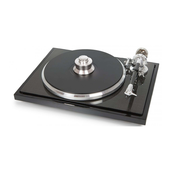
Contents Product illustrations and key Setup 1. Transport screws 2. Sub-platter and drive belt installation 3. Platter installation 4. Tonearm assembly a) Cartridge assembly b) Counterweight assembly c) Vertical Tracking Force setting (VTF) d) Tonearm output connection e) Vertical Tracking Angle setting (VTA) 11-12 f) Azimuth setting 12-13... - Page 5 KEY: CONTROLS, FEATURES AND CONNECTIONS 1. ON/OFF switch 2. Platter with bonded vinyl mat 3. Record clamp 4. Tonearm counterweight 5. Tonearm lift lever 6. Tonearm rest 7. Headshell with finger lift 8. Anti-skating mechanism 9. Floating sub-chassis 10. RCA output with earth connection 11.
-
Page 6: Transport Screws
SETUP 1. Transport screws Remove the three transport screws (15) from the carbon part of the chassis before installing the sub-platter (14), the drive belt (13) and the platter (2). The transport screws are used to ensure safe shipping and transport, and should be reinstalled prior to any future shipment or transportation of the turntable. -
Page 7: Platter Installation
3. Platter installation Install the platter (2) on the sub-platter (14). -
Page 8: Tonearm Assembly
4. Tonearm assembly The tonearm includes a combination of cardan and uni pivot bearings, immersed in special damping fluid. See the next steps to set up your tonearm. -
Page 9: A) Cartridge Assembly
a) Cartridge installation Install the cartridge into the aluminium headshell, using the appropriate hardware included with your cartridge. Connect the cartridge as indicated below: • White left channel L+ • Red right channel R+ • Green right channel R- • Blue left channel L- For correct cartridge alignment, use the two-point cartridge alignment protractor provided with your C-Sharp accessories. -
Page 10: C) Vertical Tracking Force Setting (Vtf)
c) Vertical Tracking Force setting (VTF) Before setting the Vertical Tracking Force, confirm the exact weight of your cartridge. Depending on your cartridge weight, determine whether to use the counterweight with or without the additional insert, in accordance with the specifications above. Pushing carefully, turn the counterweight onto the rear end of the counterweight support rod as shown in the illustration below. -
Page 11: D) Tonearm Output Connection
d) Tonearm output connection Connect the tonearm cable provided with the accessories to the RCA tonearm output that is located at the rear of the turntable, behind the tonearm. Connect the grounding cable on the earth connection screw. e) Vertical Tracking Angle setting (VTA) To set the Vertical Tracking Angle, first put a record on the platter. -
Page 12: F) Azimuth Setting
f) Azimuth setting The cartridge needle must be perpendicular to the record in order to trace the groove wall modulations correctly. The azimuth (angle) is precisely set by the factory. In the event that you need to modify this setting, however, follow the instructions below. Step 1: Unscrew the small UNI PIVOT LOCKING SCREW using the 1.5 mm hexagonal key provided in the accessories. - Page 13 xamples of incorrect azimuth setup: Too much left angle: Too much right angle: The correct position is 100% perpendicular to the record.
-
Page 14: G) Anti-Skating Assembly And Adjustment
g) Anti-skating assembly and adjustment The anti-skating mechanism is shipped partially disassembled to avoid damage during transport. For correct installation, please follow the steps below. Step 1: Prepare all parts supplied from the accessories bag: • Anti-skating sliding mechanism with anti-skating weight and thread for mounting on the tonearm •... - Page 15 Step 3: The anti-skating sliding mechanism is supplied with a pre-mounted anti-skating weight and anti- skating thread. Put the eye of the anti-skating thread around the hole for the HOOK SCREW and screw the HOOK SCREW into the tonearm through the eye of the anti-skating thread as shown in the illustration below.
-
Page 16: Leveling The Turntable
Step 5: Anti-skating force adjustment: Adjust the anti-skating force by positioning the weight on the appropriate groove of the anti- skating sliding mechanism. Anti-skating downforce should be adjusted in correspondence with the tonearm downforce as follows: Tonearm downforce: Anti-skating groove: Lower than 13 mN or 1.3 grams groove from bearing 13–18 mN or 1.3–1.8 grams... -
Page 17: Using The Record Clamp, Starting The Motor, Changing The Speed
Three precision adjustable damped feet are mounted under the turntable for leveling the turntable. Once the turntable is in final position, put the supplied spirit level on the carbon fiber sub-chassis, and then level the turntable by screwing or unscrewing the feet as needed. It is advisable to check level from several positions on the subchassis. -
Page 18: Technical Specifications
7. Technical Specifications E.A.T. C-Sharp Model C-Major Nominal speed 33/45 rpm, manual speed change Speed variance 33rpm: ± < 0.09%, 45rpm: ± < 0.10% Wow and flutter 33rpm: ± < 0.05%, 45rpm: ± < 0.05% Signal to noise S/N Ratio (mechanical noise): - 40 dB S/N... -
Page 19: Troubleshooting, Warranty, Service
Troubleshooting The platter doesn’t turn although the unit is switched on: • The unit is not connected to the mains power supply (the building’s electrical system). • No mains power is being delivered at the socket. • The drive belt is not fitted properly or has slipped off. No signal through one or both channels: •...
Need help?
Do you have a question about the C-Major and is the answer not in the manual?
Questions and answers